

Page 1
SOLAR COLLECTOR FLAT ROOF MOUNTING INSTRUCTIONS
CAUTION
ALL PERSONS WORKING ON ROOFS SHOULD
HAVE SUCCESSFULLY COMPLETED A FALL SAFETY
COURSE AND SHOULD BE PROPERLY EQUIPPED
WITH THE APPROPRIATE SAFETY EQUIPMENT
WARNING
AFTER COMPLETION OF THE COLLECTOR
MOUNTING AND PRIOR TO SYSTEM CHARGING THE
COLLECTORS MUST BE COVERED BY A BLANKET OR
OTHER MEANS TO AVOID SOLAR RADIAT ION FROM
HEATING THE COLLECTORS. THE SURFACES OF THE
COLLECTOR CAN BECOME EXTREMELY HOT AND
COULD POSE A BURN HAZARD.
The most important structural consideration is to securely
anchor the solar collector and the mounting hardware to the
125 Southeast Parkway, Franklin, TN 37068
PHONE: 1-800-433-2545 • FAX: 1-800-433-2515
structural members of the roof with the stainless steel hardware
provided. The solar collector must be attached to the mounting
hardware. See Figure 8.
Preserving the integrity of the roof membrane is the
mostimportantroongconsideration.Ensurethatallroof
penetrations required to plumb and mount the solar collector
areproperlyashedandsealedinaccordancewithstandard
roongpractices.
If the region is subject to hurricane conditions, additional
steps may be required to secure the collector and mounting
hardware to the structural members. In certain areas of the
country, local building codes may require collector wind load
testingorprescribespecicmountingprocedures.Consult
your local building department.
Install the collectors as described in the Flat Roof Mounting
instructions.
BASIC TOOLS AND MATERIALS
Drill & Drill Bits
#3 Phillips Head Bit
#3 Phillips Head Screwdriver
Extension Cord
Tape Measure
Chalk Line
Utility Knife
Level
Pliers
FLAT ROOF MOUNTING
PREPARATION:
1. Determine the type of roof that the solar collector flat
roof mounting hardware is to be installed on.
2. Determine the roof construction, i.e.,
a. Roofing material over insulation, over steel deck
b. Roofing material over insulation, over wood deck
c. Roofing material over insulation, over concrete deck
d. Roofing material over wood deck only
e. Roofing material over concrete deck only
f. Roofing material over recovery board, insulation, and
wood, concrete, or metal
g. Other
3. Choose the appropriate fastener to work in conjunction
with the given roof construction. #14 x 3” Heavy Duty
Roof Fasteners have been included with this kit to cover
the majority of roof constructions. If a longer fastener is
required, use only OMG brand or equivalent. Be sure
the fasteners are long enough to penetrate the deck.
OMG Heavy Duty Roof Fasteners for concrete and
other decks will need to be determined by your installer
or architect. See Figure 7.
8” & 10” Adjustable Wrenches
7/16” & 9/16” Wrenches
Ratchet & 7/16” & 9/16” Sockets
Target Patch (Flashing)
Roof Sealant
6’ x 8’ or 6’ x 10’ Tarp (1 per collector)
Installation Hardware (Supplied) Includes:
• Hardware & Mounting Brackets
INSTALLATION INSTRUCTIONS
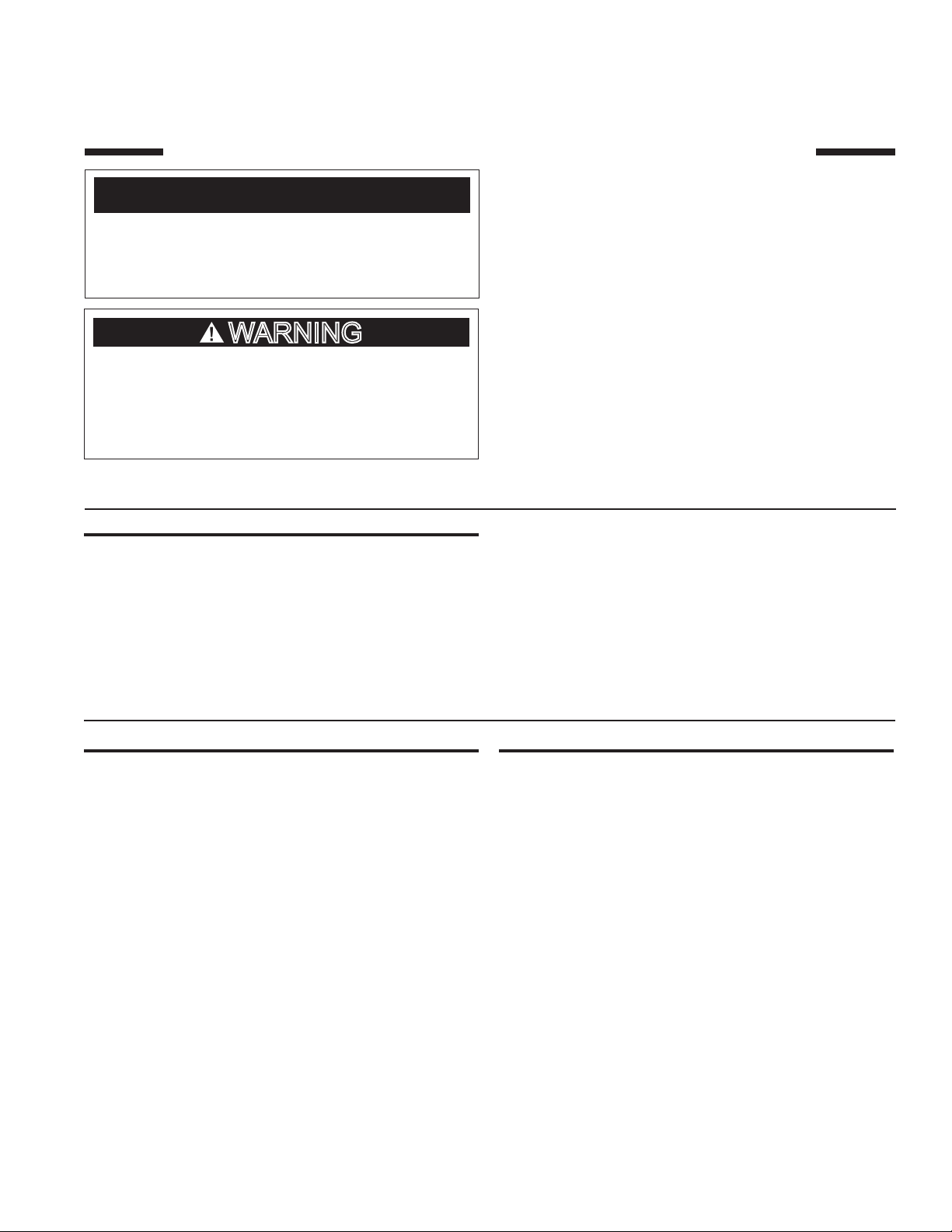
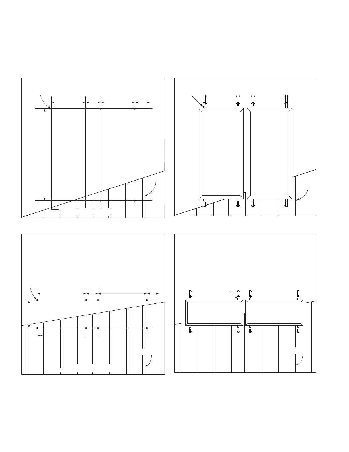
1. Locate the mounting points from Figures 1 & 2 and
Table 1 for vertical mount. Figures 3 & 4 and Table 2 for
horizontal mount. Layout the roof as specified.
2. Place the base plate on top of the finished roof (the base
plate is the flat metal piece with two threaded studs).
Align the base plate so that the studs are oriented in the
desired direction for application of the top plate.
3. Install the included #14 x 3” OMG Heavy Duty Roof
Fasteners or other suitable fasteners (dependent upon
the roofing material type) through the holes in the
perimeter of the base plate. See Figures 5 & 8.
4. Apply a generous amount of an approved roof sealant
around the base of the threaded rods.
5. Install a 10” x 10” target patch (patch material is to match
the roofing material installed on the roof) over the base
plate. Cut two small holes in the target patch so that when
it is installed it will fit tightly over the threaded studs and
be centered over the base plate. See Figure 6.
6. Apply target patch over the base plate using proper
mastic techniques so as to create a water tight patch.
This will vary dependent upon the type of roofing material.
PRINTED 0311 319542-001
1
Page 2
7. The threaded studs should be the only part of the base
plate that is exposed. There may be bleed out of the
sealant applied around the studs. When the top plate is
installed this will help create a water tight compression
fitting. See Figure 5.
8. Install the top plate over the base plate threaded studs.
The top plate should be centered on the base plate when
installed properly. See Figure 5.
9. Install an EPDM bonded washer, stainless steel lock
washer, and hex nut over each stud and tighten. See
Figure 5.
10. Repeat steps as needed for the remainder of the
mounting bracket locations.
MOUNTING
POINTS
A”
B” B”C”
D”
VERTICAL MOUNT
BASED ON 16” CENTER RAFTERS
Figure 1. Figure 2.
MOUNTING
BRACKETS
C”
RAFTER
RAFTER
MOUNTING
POINTS
A”
D”
B” B”C”
HORIZONTAL MOUNT
BASED ON 16” CENTER RAFTERS
Figure 3.
C”
RAFTER
MOUNTING
BRACKETS
RAFTER
Figure 4.
2
Page 3

NOTICE
WHEN MOUNTING THE TILT MOUNT KIT REFER TO THE
SOLAR COLLECTOR TILT MOUNT INSTRUCTIONS FOR
ASSEMBLY.
* THE “A” DIMENSION IS USED FOR MOUNTING WITH
THE TILT MOUNT KIT ONLY.
COLLECTOR
Vert 3.5’ X 7’ 15° 91.00 32.00 14.00 7.25
Vert 3.5’ X 7’ 30° 84.00 32.00 14.00 7.25
Vert 3.5’ X 7’ 45° 73.00 32.00 14.00 7.25
Vert 3.5’ X 7’ 60° 40.25 32.00 14.00 7.25
Vert 3.5’ X 7’ 75° 26.50 32.00 14.00 7.25
Vert 4’ X 8’ 15° 95.75 35.00 16.00 11.75
Vert 4’ X 8’ 30° 87.50 35.00 16.00 11.75
Vert 4’ X 8’ 45° 77.25 35.00 16.00 11.75
Vert 4’ X 8’ 60° 48.00 35.00 16.00 11.75
Vert 4’ X 8’ 75° 27.50 35.00 16.00 11.75
Vert 4’ X 10’ 15° 119.25 35.00 16.00 11.75
Vert 4’ X 10’ 30° 106.00 35.00 16.00 11.75
Vert 4’ X 10’ 45° 92.75 35.00 16.00 11.75
Vert 4’ X 10’ 60° 65.00 35.00 16.00 11.75
Vert 4’ X 10’ 75° 61.50 35.00 16.00 11.75
TILT
ANGLE
“A” * “B” “C” “D”
Table 1.
COLLECTOR
Horiz 3.5’ X 7’ 15° 44.00 62.00 28.00 13.50
Horiz 3.5’ X 7’ 30° 40.25 62.00 28.00 13.50
Horiz 3.5’ X 7’ 45° 31.75 62.00 28.00 13.50
Horiz 3.5’ X 7’ 60° 20.50 62.00 28.00 13.50
Horiz 3.5’ X 7’ 75° 9.00 62.00 28.00 13.50
Horiz 4’ X 8’ 15° 50.00 72.00 28.00 12.00
Horiz 4’ X 8’ 30° 45.25 72.00 28.00 12.00
Horiz 4’ X 8’ 45° 37.50 72.00 28.00 12.00
Horiz 4’ X 8’ 60° 27.75 72.00 28.00 12.00
Horiz 4’ X 8’ 75° 14.75 72.00 28.00 12.00
Horiz 4’ X 10’ 15° 50.00 94.00 30.00 9.00
Horiz 4’ X 10’ 30° 45.25 94.00 30.00 9.00
Horiz 4’ X 10’ 45° 37.50 94.00 30.00 9.00
Horiz 4’ X 10’ 60° 27.75 94.00 30.00 9.00
Horiz 4’ X 10’ 75° 14.75 94.00 30.00 9.00
TILT
ANGLE
“A” * “B” “C” “D”
Table 2.
3
Page 4

TOP
DECK
10.00
PLATE
TARGET
PATC H
SS HEX
NUTS
EPDM
WASHERS
SS LOCK
WASHERS
FASTENERS
10.00
BASE
PLATE
INSULATION
STUD
HOLES
ACCEPATBLE
ROOF SEALANT
BLEED THROUGH
MEMBRANE
STEEL
WOOD BLOCKING
Figure 5.
TARGET PATCH
Figure 6.
Figure 7.
4
Page 5

ATTACHING COLLECTOR TO MOUNTING BRACKETS
Once all of the mounting brackets have been secured to
the roof the solar collector(s) can be installed. See Figure
8 for these instructions.
1. Insert the stainless steel channel nut w/spring inside
of the mounting strut.
2. Fasten the solar collector mounting clip to the channel
nutwiththestainlesssteelbolt,lock-washer,andat
washer as shown. Do not tighten. Repeat step for the
other mounting bracket locations.
3. The solar collector can now be set on the mounting
struts. To aid in handling the collectors on the roof the
mounting clips may be tightened to the lower mounting brackets prior to raising the collectors. The collec-
SOLAR
COLLECTOR
FRAME
STAINLESS STEEL BOLT,
LOCK WASHER,
& FLAT WASHER
MOUNTING
CLIP
CHANNEL NUT
with SPRING
(One Piece Part)
tor can then be set on the lower mounting brackets
while the top clips are fastened over the lip on the collector frame.
4. After the solar collector is in position, locate the upper
mounting clip so that its lip over-hangs the lip of the
solar collector frame as shown. Tighten the mounting
clip to the solar collector frame securely. Repeat for
the other upper mounting clips.
5. Once the upper mounting clips are secured, the bottom mounting clips can be loosened and retightened
over the collector lip as directed in step 4.
6. Repeat steps as needed for other solar collectors.
OMG
SCREWS
C-CHANNEL
TILT RISER
Figure 8.
MOUNTING
STRUT
4”
MOUNTING
STRUT
M10-1.25 BOLT
TOP
PLATE
TARGET
PATC H
5
 Loading...