

Page 1

L.-
i-. .,
L-
L..
I .d
L.
L I
XR-1020
XR-1520
MULTI-FONT
USERS MANUAL
i .
NOT INTENDED FOR SALE
Page 2

Federal Communications Commission
Radio Frquettcy Interference Statement
lllisq .
to Part 1 of FCC Rules. ‘lltese limits ate designed to provide masonable ptotection against harmful
interfemce in a residential installation. ‘lIis equipment generates, uses and can radiate radio f ency
e-rmgy and. if not installed and used in aeeotdmce with the. instmctions. may cause. harmful inte 7 emnce
to radio
installati~. If this equipment does cause harmful interferena to radio or telex&ion recepti~, which can
bcdeterminedbytumingtheequipnmtoffnnd~theurerbmcwrPgedtotrytocorrectthel
by me or mote of the folIowing measures:
Unauthorized modifications of this product by the user will void his authority
unless expressly approved by the party responsible for comphanq.
em has been tested and found to compIy with the limits for a Class B digital device. pursuant
T
eanmunications. However, there is no guarantee that intetference will not occur in a particular
l Reorient or relocate the receiving antemta.
l Increase the separatism between the quiPtxnt and receiver.
l Connect the equipment into m outlet on a ciratit different from that to which the receiver is
ealnectcd.
l Consult the dealer or an experienced ndiofIV technician for help.
to operate the. quipment
For comphance with the FederaI Noise Interference Standard, this equipment requires a shielded cable.
Tk above statement applies only to printers markted in tk USA.
The Canadian Departme.nt of Communications
Radio Interference Regulations
This digmd apparatus does not exceed the class B limits for radio n&e. emissions from digital apparahts
set out in the Radio Intesfesmce ReguIations of the Canadian Depattmqt of Communications.
Le. prCsent appamil num&ique n’6men pas de bruits radiokkctriques d6passant les limites appkables aux
appareils num&iques de la classe B prescrites dans le R&glement sur le brouillage tadiokxriqoe Mict6
par le minis& des Communications du Canada.
Tk above s&tement applies only to printers marketed in Canadz.
Trademark Acknowledgementa
XR-1020/1520, XR-lOOO/lHO, NX-1020 Color, NX-1008 Color, LZ9, X9CL, IS-SXL, IP-128XL,
SF-lODMII/lSDMII, SPlORMIIIl5RMI1, PI’-lOXM/18XM: Star hficmnics Co., Ltd.
IBM-PC, PS/2, PC-AT, Proprinter, PC-DOS: Intenutionai Business Machines Corp.
MS-DOS, Microsoft BASIC: Microsoft Corporation
EX-80&‘1000, FX-850/105& Seiko Bpscn Corp.
NOTICE
l All rights reserved. Repmductiat of any part of this manual in any fotm whatsoever without
STAR’s express permission is forbidden.
0 lhe contacts of this mamrai are subject to change without not&.
0 AU efforts have been made to ensure the accuracy of the contents of this manupl at the time of press.
However, should any errors be detected, STAR would gently appreciate being infotmed of them.
l ‘he above notwithstanding, STAR can assome no responsibility for any errors in this manual.
St&ment of
0 Copyright 1991 Star Micronics Co., Ltd.
-
Page 3
HOW TO USE THIS MANUAL
This manual is organized into eleven chapters. To learn how to make the best
use of your printer you are urged to read through chapters 2 through 6. The
remaining chapters may be treated as a reference guide for programming
operations, etc. It assumes a degree of acknowledge of the operation of
computers (for instance, it assumes you know about hexadecimal numbers).
The chapters are as follows:
Chapter 1 - Introduction
This chapter indicates the some features of the printer, the names and those
functions of the printer components, and the actual example of font style.
: .,
Chapter 2 - Setting up the printer
This chapter explains how to get the printer unpacked and set up. Read this
chapter before you do anything else.
Chapter 3 - Optional accessories
This chapter explains the optional accessories with your printer, and how to
install them.
Chapter 4 - Paper installation and use
This chapter describes instructions for printing such as selecting paper types,
adjusting the printing gap, and installing paper.
Chapter 5 - Control panel operations
There are a number of controls on the front panel which perform various
functions related to paper handling, print modes and font selection.
After getting set up, mad this chapter and try out the procedures in it to find
.
out how the printer works.
Page 4

Chapter 6 - Setting the Memory Switches
This chapter explains how to set the Memory Switches to make system
settings on the printer.
Chapter 7 - Printer control commands
This chapter explains the different emulations provided by your printer, and
the software commands used to drive it. This section is of use if you are
writing or modifying programs to take advantage of the printer’s features.
Chapter 8 - Download characters
This chapter explains the procedures to create your own characters.
Chapter 9 - MS-DOS and your printer
Since the PW or PC-AT family of computers running under MS-DOS is
currently the most popular configuration of microcomputer, we have included
a few hints and tips to help you use your printer with such systems.
Since virtually all PCs are sold with a Microsoft BASIC interpreter, we have
also included some hints, and a sample program in this language to demonstrate
the capabilities of the printer.
Chapter 10 - Troubleshooting and maintenance
This section gives a checklist of points to check if your printer is not working
in the expected way. It also includes details of some routine maintenance
operations you can carry out yourself. It is not, however, a complete service
manual. Call a qualified service engineer if you are unsure of your ability to
carry out any maintenance or servicing operations.
Chapter 11 - Reference
This section gives some references of your printer, such as specifications of
your printer, the pinout of interface connector, the character tables.
The character table charts give the different character sets available.
- _
Page 5
TABLE OF CONTENTS
Chapter 1 INTRODUCTION
Features of the printer
Printer components
Font style example
Chapter 2 SETTING UP THE PRINTER
Locating the printer
Unpacking and inspection
Setting up
Mounting the platen knob
Install the ribbon cartridge
Connecting the interface cable
Chapter 3 OPTIONAL ACCESSORIES
Automatic Sheet Feeder
Single-Bin Automatic Sheet Feeder
Dual-Bin Automatic Sheet Feeder
Pull Tractor Unit
Interface Cartridges
DIP switch functions on the Serial Interface Cartridge
Chapter 4 PAPER INSTALLATION AND USE
Selection of paper
Adjusting the printing gap
Loading fanfold forms
Loading the paper from the rear of the printer (Push feed)
Loading the paper from the bottom of the printer
Loading the paper with Push/Pull feed
Paper parking
Paper unparking
Loading single sheets
Loading the paper without optional accessories
Loading the paper with optional Automatic Sheet Feeder
1
1
2
4
5
5
6
8
8
9
10
13
13
13
18
20
22
23
25
25
26
27
28
30
31
34
35
36
36
38
Page 6
Chapter 5 CONTROL PANEL OPERATIONS
Buttons and indicators
ON LINE button
PAPER FEED button
SET/EJECT/PARK button
PITCH button
MODE button
FONT button
Power-up functions
Short test mode
Long test mode
Print area test mode
Pitch lock mode
Font lock mode
Pitch and Font lock mode
Hexadecimal dump
Switch combination functions
Form feed
Top of form
Forward micro-feed
Reverse micro-feed
Changing the auto loading value
Clearing the buff&All reset
Selecting the print color
Selecting the ASF bin number
Store macro definition
41
41
42
42
43
43
44 -
A’
fin ‘-
46 _.
47
47 -_
47
47 48
50
50
50
51
51
51
52
52
53 .
54
-
Chapter 6 SETTING THE MEMORY SWITCHES
Menu options
Print current settings
Installation menu
Factory settings
Dot adjustment mode
5357
57
58
62
63
Page 7
Chapter 7 PRINTER CONTROL COMMANDS
Font control commands
Character set commands
Character size and pitch commands
Vertical position commands
Horizontal position commands
Graphics commands
Download character commands
Color selection commands
Other printer commands
65
66
71
74
79
85
90
93
98
99
Chapter 8 DOWNLOAD CHARACTERS
Defining your own draft characters
Defining the attribute data
Assigning the character data
Sample program
Defining your own NLQ characters
Assigning the character data with the Standard mode
Assigning the character data with the IBM mode
Chapter 9 MS-DOS AND YOUR PRINTER
Installing application software with your printer
Embedding printer commands
Programming the printer with DOS commands
Programming with BASIC
Chapter 10 TROUBLESHOOTING AND MAINTENANCE
Troubleshooting
Power supply
Printing
Paper feeding
Maintenance
Replacing the print head
103
103
104
105
106
108
108
112
117
117
118
120
123
129
129
130
130
132
135
135
Page 8
c
-.
Chapter 11 REFERENCE
Specifications
Pinout of interface connector
Parallel interface
Serial interface
Character sets
Standard character set #2
International character sets
IBM character set #2
Character set #l
IBM special character set
INDEX
COMMAND SUMMARY
137
137
141
141
142
143
144 14/
14* 154
155 -~
157
161
Page 9
Chapter I
INTRODUCTION
This printer has a full complement of features, making it an excellent partner
for a personal computer. It supports the Epson/IBM printer commands and
character sets, enabling it to print just about anything your computer can
generate, both text and graphics.
FEATURES OF THE PRINTER
Some of main features are the following:
l Versatile paper handling
Single sheets, fanfold forms, and multi-part forms (up to 5-ply) are all
accepted, and you can use eitherpusb/pull tractororfriction feed. (You can
t.
.
load fanfold forms from the rear with internal push tractor, or fanfold
forms and multi-part forms from the bottom with optional pull tractor.) A
special feature enables you to keep fanfold forms parked in readiness while
printing on other paper.
l Six bright colors
Red, blue, violet, yellow, orange and green add a color dimension to your
printed output by the optional color ribbon.
l Large variety of fonts
The printer has the following resident fonts:
.
l Draft
l Sanserif l Courier
l script
l Extensive software support
l High-Speed Draft l Tms Romn
l Prestige
l Orator l Helvet
Since it is compatible with the Epson and IBM printers, it works with any
software that supports those printers. That includes most word-processing
and graphics programs, spread-sheets, and integrated software packages.
l Easy operation
Indicator displays and beep tones provide immediate, easy to understand
feedback when you press the buttons on the control panel. The six buttons
can operate in combinations to perform a surprising variety of functions,
including micro-alignment.
1
Page 10
l Easy care and maintenance
The ribbon cartridge can be replaced in seconds the print head in a few
minutes.
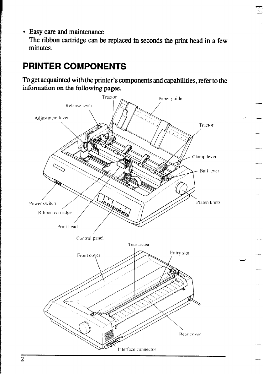
PRINTER COMPONENTS
To get acquainted with the printer’s components and capabilities, refer to the
information on the following pages.
TI-;ICIOI-
h
Paper pide
.-
-
Y
Page 11
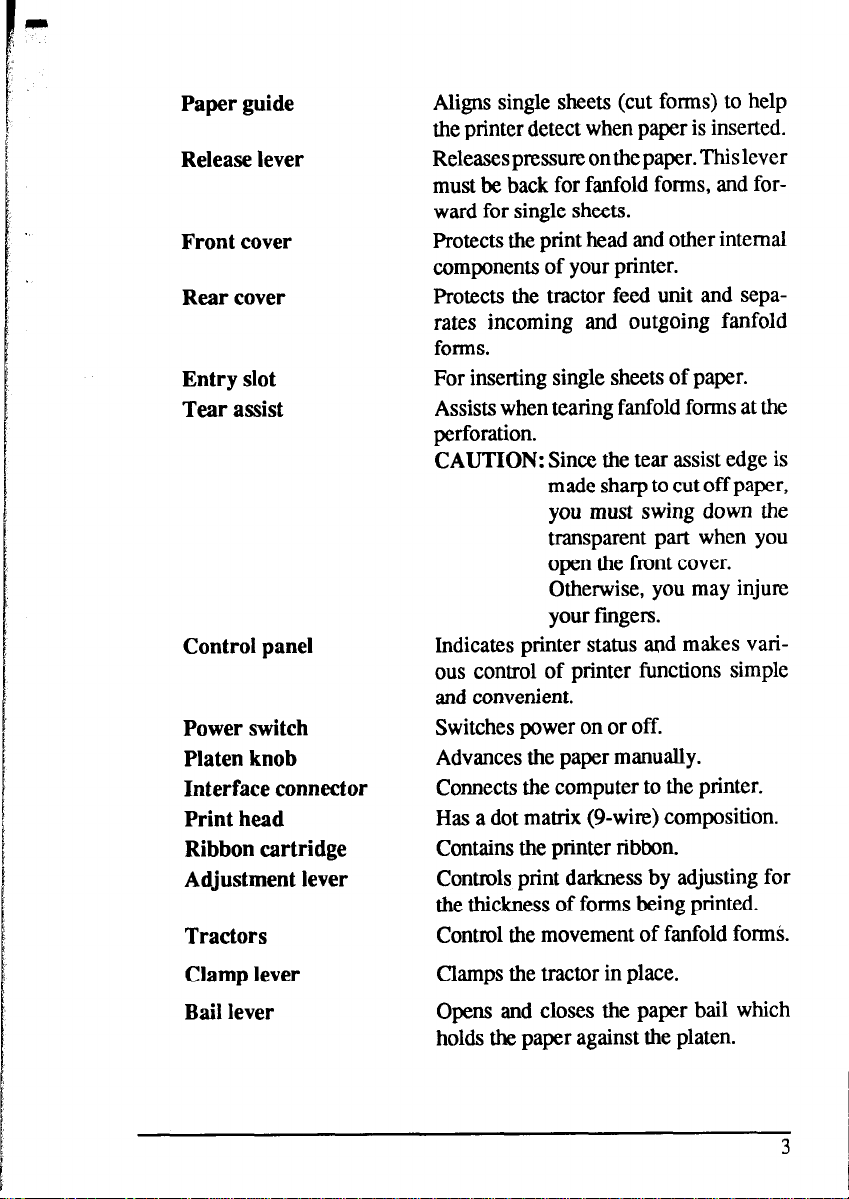
Paper guide
Release lever
Front cover
Rear cover
Entry slot
Tear assist
Control panel
Power switch
Platen knob
Interface connector
Print head
Ribbon cartridge
Adjustment lever
Tractors
Aligns single sheets (cut forms) to help
the printer detect when paper is inserted.
Releasespressureonthepaper.Thislever
must be back for fanfold forms, and forward for single sheets.
Protects the print head and other internal
components of your printer.
Protects the tractor feed unit and separates incoming and outgoing fanfold
forms.
For inserting single sheets of paper.
Assists when tearing fanfold forms at the
perforation.
CAUTION: Since the tear assist edge is
made sharp to cut off paper,
you must swing down the
transparent part when you
open the front cover.
Otherwise, you may injure
your fingers.
Indicates printer status and makes various control of printer functions simple
and convenient.
Switches power on or off.
Advances the paper manually.
Connects the computer to the printer.
Has a dot matrix (9-w&) composition.
Contains the printer ribbon.
Controls print darkness by adjusting for
the thickness of forms being printed.
Control the movement of fanfold forms.
Clamp lever
Bail lever
Clamps the tractor in place.
Opens and closes the paper bail which
holds the paper against the platen.
Page 12
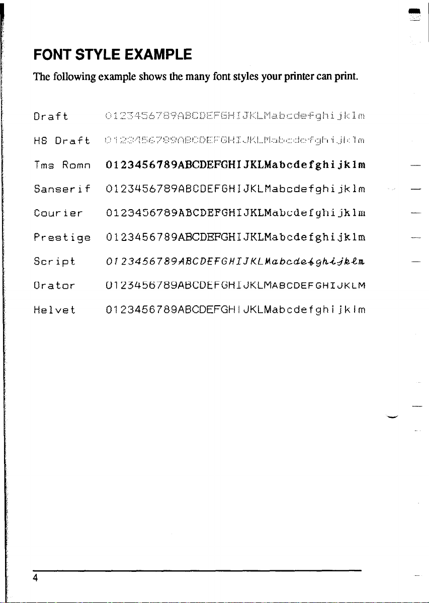
FONT STYLE EXAMPLE
The following example shows the many font styles your printer can print.
D r a f t :.:I :I. ;: ‘;j;: -<.!::; 5, ‘:? ;;;; ‘;? <; B;::; :,,j i:::. ;
H S D r a f t 1.1: ) :.:I;:::; ,i:;. i;i;c, ‘~/~:i’~~,!:::li::;;,, .,,
.-., /(( y-y i,z ),_,j /- -y ! . . . i
““l”:i’,;l(;;::‘i::jl..j :j: ,,,!I..:~I,,,i’f~~:,~,:,,::;::,il::.I.i:’;~~~~., .i .,j/:: ‘1 ;,.;
<..; ! i ,,, ,,.! ?...; ,,,, /. / .;::. i::; : .,,, > .,., F;:: i ,.;;, i \ _,. ,,j ].., _,. i i
!x, ,. 3 ,,.,..,,.. / ..;,>:; . ..(j.. .;
c I,, ‘! jri
Tms Romn 0123456789ABCDEFGHIJKLMabcdefghijklm -
Sanserif
Courier
Prestige
0123456789ABCDEFGHIJKLMabcdefghijklm
0123456789ABCDEFGHIJKLMabcdefghijklm -
0123456789ABCDEFGHIJKLMabcdefghijklm -
Script 0123450789ARCDf~GHIJKL~ubcd~~~h~~~~~
Orator
Helvet
0123456789A6CDEFGHIJKLMABCDEFGHIJKLM
0123456789AE3CDEFGMIJKLMabcdefghijklm
-
4
-
Page 13
chapter 2
SETTING UP THE PRINTER
This chapter describes the following procedures to set up your new printer.
If you have optional accessories, refer to chapter 3 after setting up the printer.
l Locating the printer
l Unpacking the carton box
l Mounting the platen knob
l Installing the ribbon cartridge
l Connecting the printer to your computer
LOCATING THE PRINTER
Before you start unpacking and setting up your printer, make sure that you
have a suitable place on which to locate it. By “a suitable place”, we mean:
l A firm, level surface which is fairly vibration-free
l Away from excessive heat (such as direct sunlight, heaters, etc)
l Away from excessive humidity
l Away from excessive dust
l Supply it with “clean” electricity. Do not connect it to the same circuit as
a large, noise-producing appliance such as a refrigerator.
. Make sure the line voltage is the voltage specified on the printer’s
identification plate.
9 To disconnect the printer, the plug has to be disconnected from the wall
socket, which has to be located close to the printer, and easy to access.
l Install the printer where there is sufficient mom for the paper and any paper
being fed in or printed out.
l If you are connecting your printer with a Centionics parallel interface,
make sure that the cable is within 2m (6ft) of the printer. An RS-232 serial
connection using the optional IS-8XL interface cartridge can be made over
longer distances.
5
Page 14
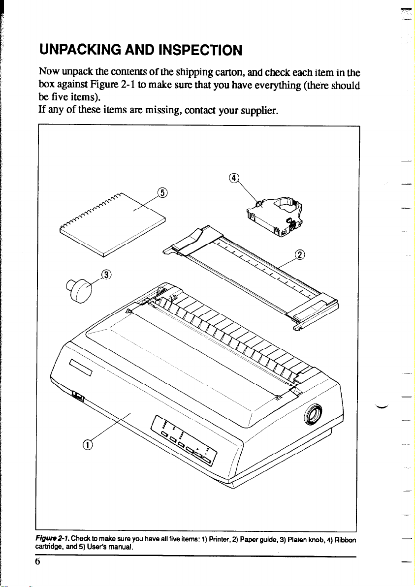
UNPACKING AND INSPECTION
Now unpack the contents of the shipping carton, and check each item in the
box against Figure 2- 1 to make sure that you have everything @h&z should
be five items).
If any of these items are missing, contact your supplier.
-
-
FrgutuZ-7. Chedc to make sure you have all five items: 1) Printer, 2) Paper guide, 3) Platen knob, 4) Ribbon
cartridge. and 5) User’s manual.
6
V
-
-
-
-
Page 15
The optional accessories which you may have ordered with your printer are:
l Color ribbon cartridge (X9cL)
l Serial interface cartridge (IS-8XL)
l Buffered parallel interface cartridge (IP- 128XL)
l Automatic sheet feeder (SF-lODMII/l5DMII, SF-lOFU4II/l5RMII)
l Pull tractor unit (PT-lOXM/lSXM)
For details of the optional accessories, refer to Chapter 3.
Page 16
SETTING UP
Place the printer in the desired location, and remove all packing material
from inside the printer cover. This packing material is intended to prevent
damage to the printer while in transit. You will want to keep all the packing
material, along with the printer carton, in case you have to move the printer
to a new location.
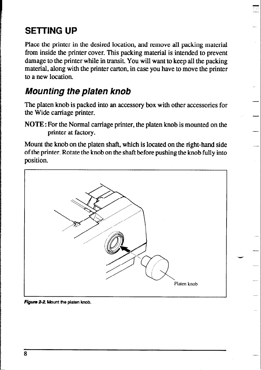
Mounting the platen knob
The platen knob is packed into an accessory box with other accessories for
the Wide carriage printer.
NOTE : For the Normal carriage printer, the platen knob is mounted on the
printer at factory.
Mount the knob on the platen shaft, which is located on the right-hand side
of the printer. Rotate the knob on the shaft before pushing the knob fully into
position.
-
-
-
Flgurr 2-2 Mount the platen knob.
8
-
‘4
Platen knob
Page 17
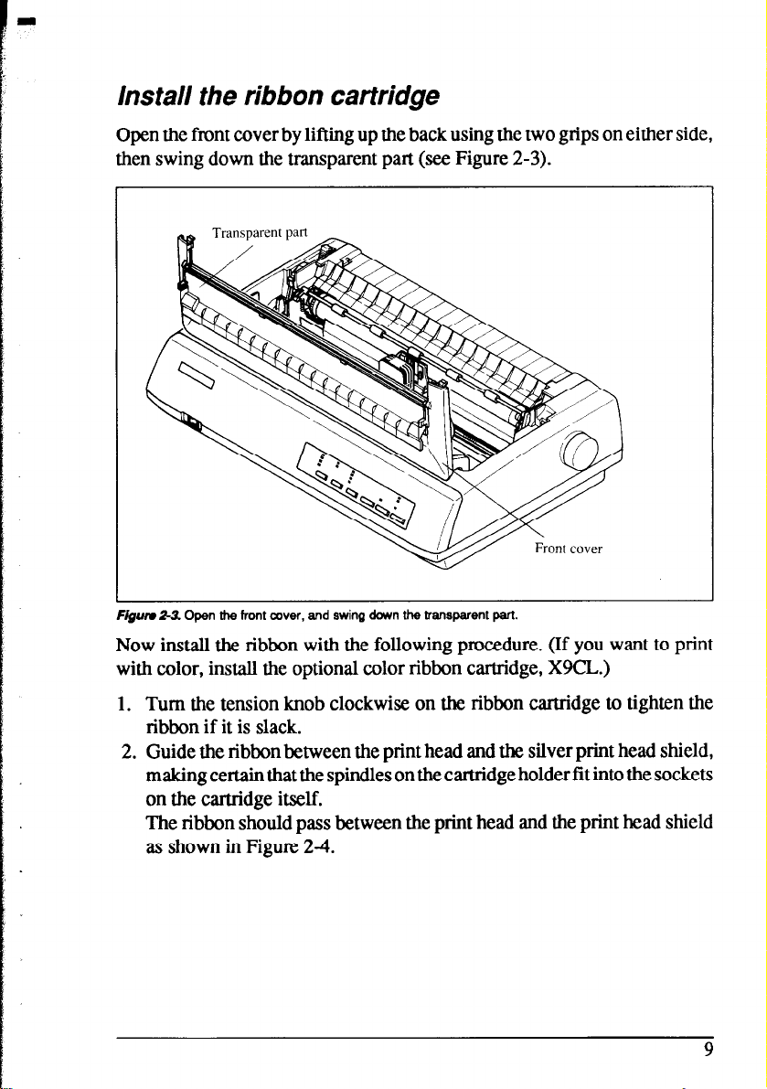
Install the ribbon cartridge
Open the front cover by lifting up the back using the two grips on either side,
then swing down the transparent part (see Figure 2-3).
Flgurr 2L3. Open the front cover, and swing down the transparent part.
Now install the ribbon with the following procedure. (If you want to print
with color, install the optional color ribbon cartridge, X9CL.)
1. Turn the tension knob clockwise on the ribbon cartridge to tighten the
ribbon if it is slack.
2. Guide the ribbon between the print head and the silver print head shield,
making certain that the spindles on the cartridge holder fit into the sockets
on the cartridge itself.
The ribbon should pass between the print head and the print head shield
as shown in Figure 24.
9
Page 18
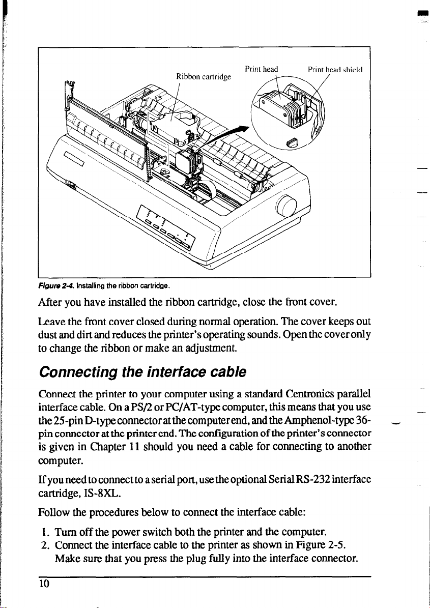
Print head
Figure Z-4. Installing the ribbon cartridge.
Print head shield
After you have installed the ribbon cartridge, close the front cover.
Leave the front cover closed during normal operation. The cover keeps out
dust and dirt and reduces the printer’s operating sounds. Open the cover only
to change the ribbon or make an adjustment.
-
-
Connecting the interface cable
Connect the printer to your computer using a standard Centronics parallel
interface cable. On a PS/2 or PC/AT-type computer, this means that you use
the 25-pin D-type connector at the computer end, and the Amphenol-type 36pin connector at the printer end. The configuration of the printer’s connector
is given in Chapter 11 should you need a cable for connecting to another
computer.
If you need to connect to a serial port, use the optional Serial RS-232 interface
cartridge, IS-8XL.
Follow the procedures below to connect the interface cable:
1. Turn off the power switch both the printer and the computer.
2. Connect the interface cable to the printer as shown in Figure 2-5.
Make sure that you press the plug fully into the interface connector.
10
Page 19

Interface cable
F@m Z-5. Connecting the interface cable.
3. Move both clips inside the extended prongs on the sides of the plug until
you hear a click.
Figurn 2-6. Move the clips until you hear a did.
4. Connect the other end of the interface cable to your computer. Use your
computer instructions to attach the interface cable.
NOTE: Because you need your computer when you start printing, ensure
that it is completely installed.
Plug the printer into a suitable outlet. However, DO NOT turn on the power
switch at the front of the printer yet.
NOTE: To disconnect the printer the plug has to be disconnected from the
wall socket, which has to be located close to the printer, and easy to
access.
11
Page 20
MEMO
”
-
Page 21
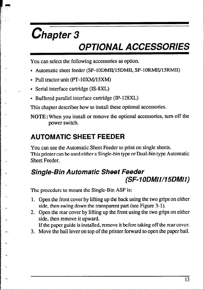
Chapter 3
OPTIONAL ACCESSORIES
You can select the following accessories as option.
l Automatic sheet feeder (SF-lODMII/15DMII, SF-lORMII/
l Pull tractor unit (PT-lOXIW5XM)
l Serial interface cartridge (IS-8XL)
l Buffered parallel interface cartridge (IP-128XL)
15RMII)
This chapter describes how to install these optional accessories.
NOTE : When you install or remove the optional accessories, turn off the
power switch.
AUTOMATIC SHEET FEEDER
You can use the Automatic Sheet Feeder to print on single sheets.
This printer can be used either a Single-bin type or Dual-bin type Automatic
Sheet Feeder.
Single- Bin A utoma tic Sheet Feeder
(SF- 1 ODMIUI 5DMII)
The procedure to mount the Single-Bin ASF is:
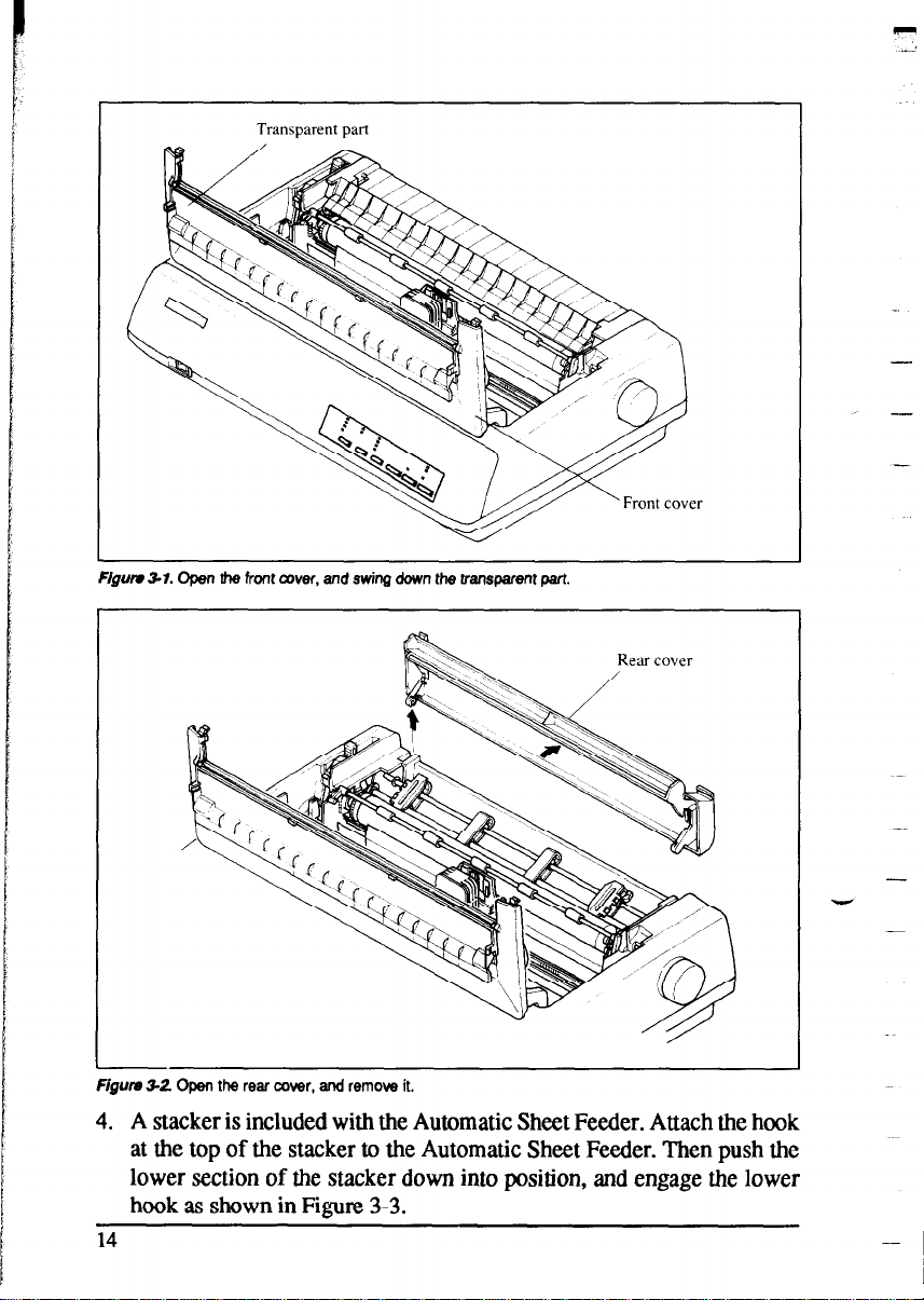
1. Open the front cover by lifting up the back using the two grips on either
side, then swing down the transparent part (see Figure 3-l).
2. Open the rear cover by lifting up the front using the two grips on either
side, then remove it upward.
If the paper guide is installed, remove it before taking off the rear cover.
3. Move the bail lever on top of the printer forward to open the paper bail.
13
Page 22
Transparent part
Figwv 3-l. Open the front cover, and swing down the transparent part.
P
2
-
-
Figum 32 Open the rear cover, and remove it.
4. A stacker is included with the Automatic Sheet Feeder. Attach the hook
at the top of the stacker to the Automatic Sheet Feeder. Then push the
lower section of the stacker down into position, and engage the lower
hook as shown in Figure 3-3.
14
-
-
-
Page 23
i
.
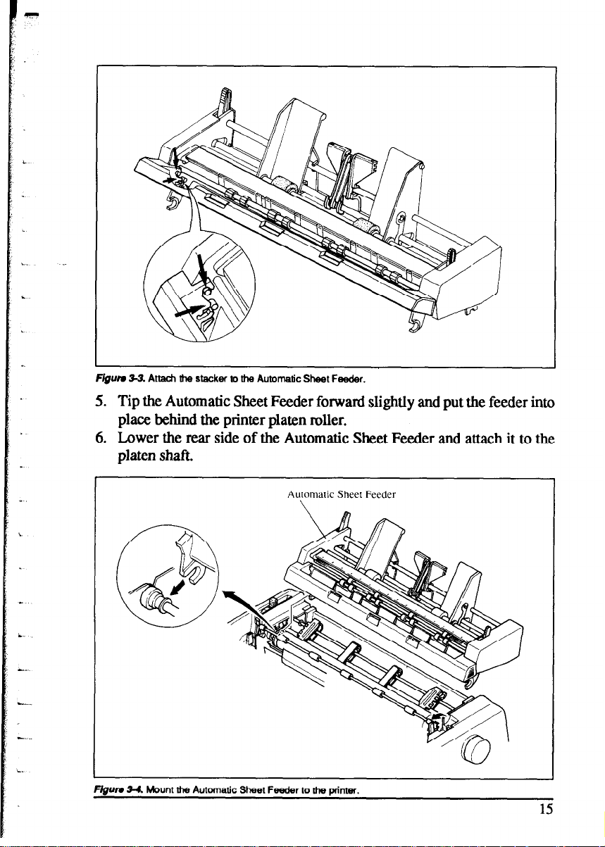
F&m 33. Attach the stacker to the Automatic Sheet Feeder.
Tip the Automatic Sheet Feeder forward slightly and put the feeder into
5.
place behind the printer platen roller.
Lower the rear side of the Automatic Sheet Feeder and attach it to the
6.
platen shaft.
Automatic Sheet Feeder
. .
I.
Frgum 34.
Mount the Automatic
Feeder to U-m pdntw.
Sheet
15
Page 24
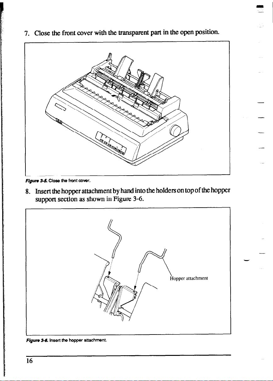
7. Close the front cover with the transparent part in the open position.
F/gum 3-S Close he front cover.
I
-
8.
Insert the hopper attachment by hand into the holders on top of the hopper
support section as shown in Figure 3-6.
opper attachment
Figum 36. Insert the hopper attachment.
Page 25
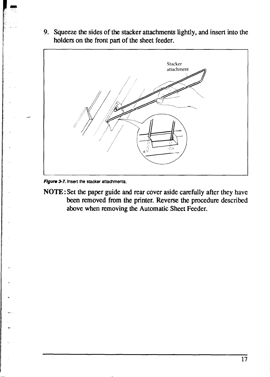
9. Squeeze the sides of the stacker attachments lightly, and insert into the
holders on the front part of the sheet feeder.
Figum 3-7. insert the stacker attachments,
NOTE : Set the paper guide and rear cover aside carefully after they have
been removed from the printer. Reverse the procedure described
above when removing the Automatic Sheet Feeder.
Page 26
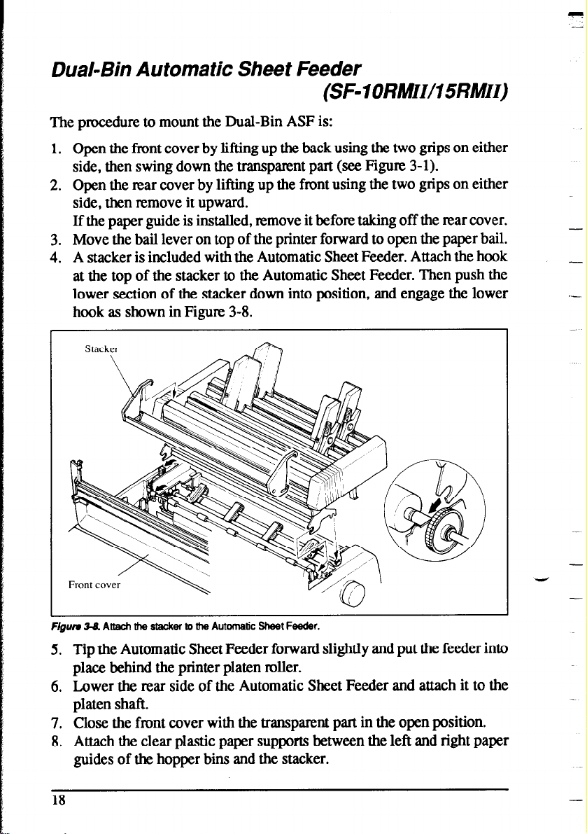
Dual-Bin Automatic Sheet Feeder
(SF- 1 ORMWI5RMII)
The procedure to mount the Dual-Bin ASF is:
1. Open the front cover by lifting up the back using the two grips on either
side, then swing down the transparent part (see Figure 3-l).
2. Open the rear cover by lifting up the front using the two grips on either
side, then remove it upward.
If the paper guide is installed, remove it before taking off the rear cover.
3. Move the bail lever on top of the printer forward to open the paper bail.
4. A stacker is included with the Automatic Sheet Feeder. Attach the hook
at the top of the stacker to the Automatic Sheet Feeder. Then push the
lower section of the stacker down into position, and engage the lower
hook as shown in Figure 3-8.
-
.-
Figurn 38 Attach the stacker to the Automatic Sheet Feeder.
5. Tip the Automatic Sheet Feeder forward slightly and put the feeder into
place behind the printer platen roller.
6. Lower the rear side of the Automatic Sheet Feeder and attach it to the
platen shaft.
7. Close the front cover with the transparent part in the open position.
8. Attach the clear plastic paper supports between the left and right paper
guides of the hopper bins and the stacker.
18
-
Page 27
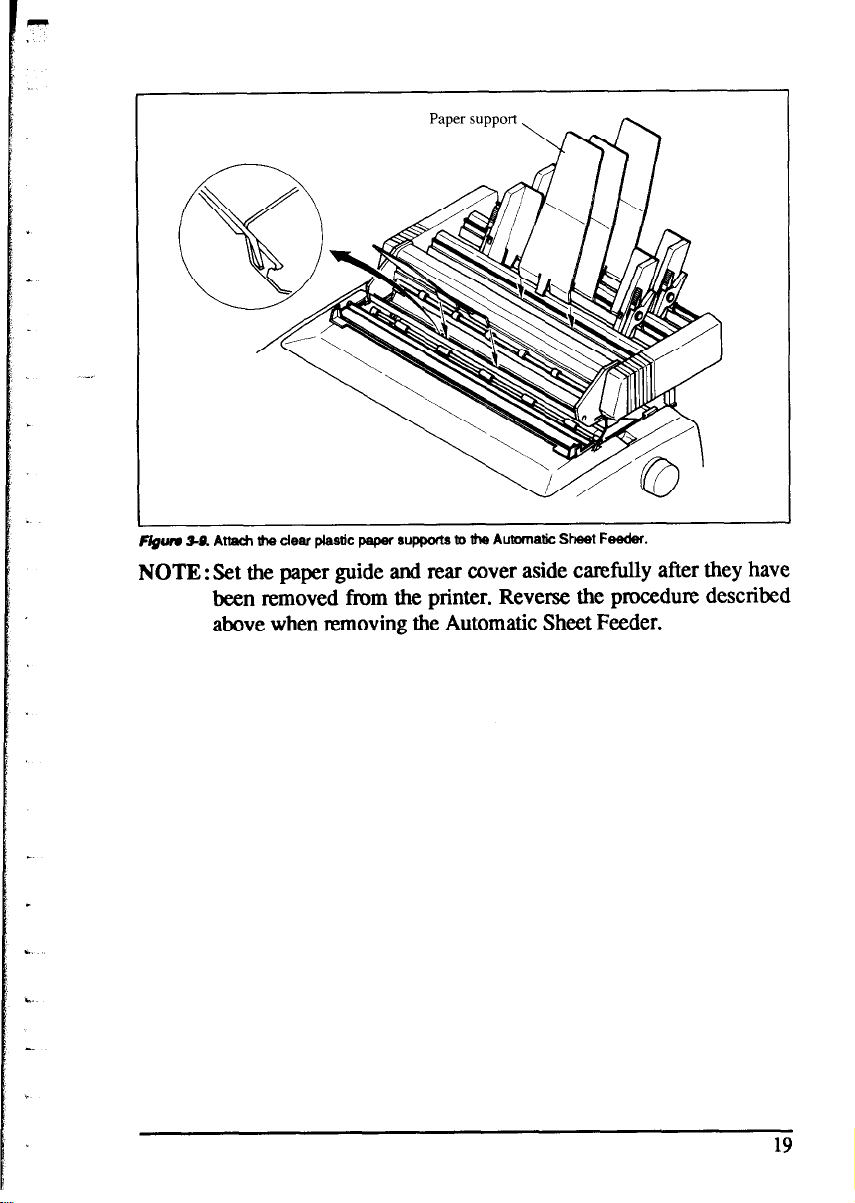
NOTE : Set the paper guide and rear cover aside carefully after they have
been removed from the printer. Reverse the procedure described
above when removing the Automatic Sheet Feeder.
19
Page 28
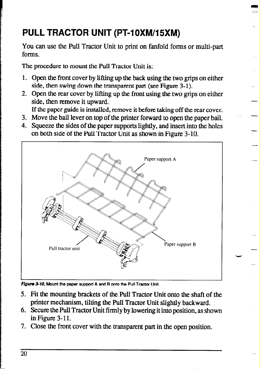
PULL TRACTOR UNIT (PT-1 OXM/15XM)
You can use the FW Tractor Unit to print on fanfold forms or multi-part
forms.
The procedure to mount the Pull Tractor Unit is:
1. Open the front cover by lifting up the back using the two grips on either
side, then swing down the transparent part (see Figure 3- 1).
2. Open the rear cover by lifting up the front using the two grips on either
side, then remove it upward.
If the paper guide is installed, remove it before taking off the rear cover.
3. Move the bail lever on top of the printer forward to open the paper bail.
4. Squeeze the sides of the paper supports lightly, and insert into the holes
on both side of the Pull Tractor Unit as shown in Figure 3-10.
-
-
support B
-. - _ - . .
rlgum ~7~7. Mounl me paper support A and B onto me Pull TraCtOr Unit.
_ .- -..-
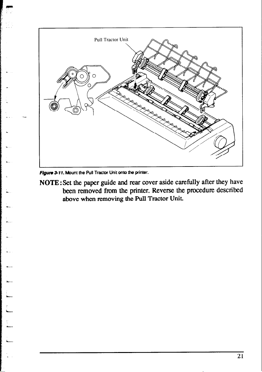
5. Fit the mounting brackets of the F%ll Tractor Unit onto the shaft of the
printer mechanism, tilting the Pull Tractor Unit slightly backward.
6. Secure the Pull Tractor Unit firmly by lowering it into position, as shown
inFigure 3-11.
7. Close the front cover with the transparent part in the open position.
20
-
Page 29
w
I
L
. .w..
L
.
.
Pull Tractor Un’
i
L
L._
Flgum 3-W. Mount the Pull Tractor Unit onto the printer.
NOTE : Set the paper guide and rear cover aside carefully after they have
been removed from the printer. Reverse the procedure described
above when removing the FWl Tractor Unit.
21
Page 30
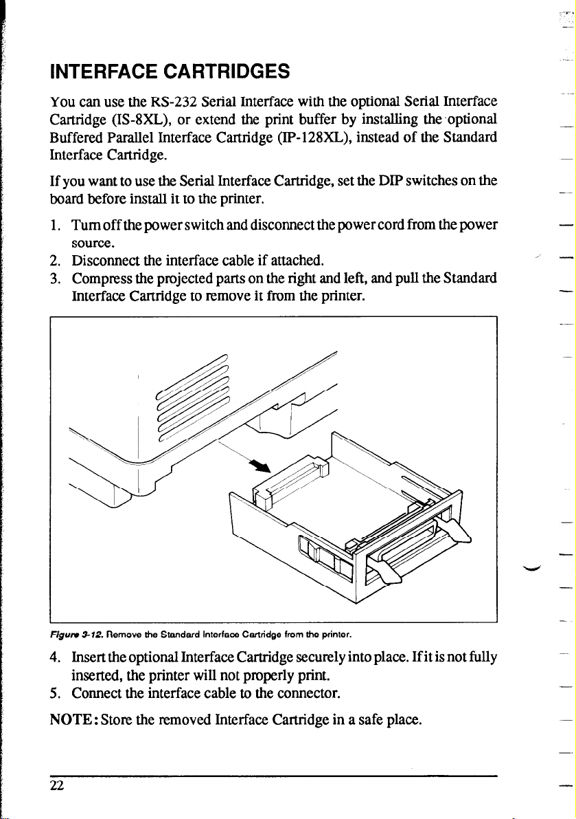
INTERFACE CARTRIDGES
You can use the RS-232 Serial Interface with the optional Serial Interface
Cartridge (IS-8XL), or extend the print buffer by installing the .optional
Buffered Parallel Interface Cartridge (IP-128XL), instead of the Standard
Interface Cartridge.
If you want to use the Serial Interface Cartridge, set the DIP switches on the
board before install it to the printer.
1. Turn off the power switch and disconnect the power cord from the power source.
2. Disconnect the interface cable if attached.
3. Compress the projected parts on the right and left, and pull the Standard
Interface Cartridge to remove it from the printer.
, -
-
Flgurr 312. Remove the Standard Interface Cartridge from the printer.
4. Insert the optional Interface Cartridge securely into place. If it is not fully
inserted, the printer will not properly print.
5. Connect the interface cable to the connector.
NOTE : Store the removed Interface Cartridge in a safe place.
22
-
-
Page 31

DIP Switch Functions on The Serial Interface
Cartridge
It is necessary to make compatible the data transfer conditions between the
computer and the serial interface board with the DIP switch settings on the
serial interface board.
Following table shows the
Interface Caruidge.
switch Function
.-
1 Data length
2 Parity condition
3
4 Data Protocol
5 Parity condition
6
7 Transfer speed
8
functions of the DIP switches on the Serial
[Parity condition]
iz-+E
(Refer below)
(Refer below)
(Refer below)
(Refer below)
[Transfer speed]
Switch 6 Switch 7 Switch 8 Transfer speed
OFF OFF OFF
OFF OFF ON
[Data protocol]
150 BPS
300 BPS
ON OFF ON
ON ON OFF
ON ON ON
4800 BPS
9600 BPS
19200 BPS
23
Page 32

..-
MEMO
-
Page 33

chapter 4
PAPER INSTALLATIONAND USE
This chapter describes instructions forprinting such as selecting paper types,
adjusting the printing gap, and installing paper.
SELECTION OF PAPER
.-
Your printer accepts any of the following papers:
l Single sheets (cut forms) and stationery
Use the friction feed or the optional Automatic Sheet Feeder.
l Fanfold forms
Fanfold forms have holes along the sides and perforations between the
sheets. They are also called sprocket forms, punched forms, or just plain
“computer paper”.
Printing on or near the perforations of continuous fanfold forms may
reduce printing quality, misalign the fanfold forms, or cause a paper jam.
It is recommended not to print within an area of one inch before and after
the perforations.
l Multi-part forms
You can use multi-part forms mat have up to five parts including the
original when the Multi-part mode is selected with the Memory Switch
setting. (For details, please refer to Chapter 6.)
Use pressure sensitive multi-part forms with both side edges glued and a
difference in thickness of O.OSmm or less between the side edges. It is
recommended to use the bottom feed with the optional Fbll Tractor Unit
to get fine alignment.
NOTE: Care should be taken in color printing with continuous multi-part
forms. Side edges of paper might be damaged.
l Preprinted forms
Page 34

Figure 4-l shows the recommended print area for each type of papers.
Fanfold forms
IX
m
c*XO mm for Push Feed)
Figuru 41. Recommended print area for acceptable papers.
Single sheets
20 mm
5mm Smm
23 mm
ADJUSTING THE PRINTING GAP
The distance between the print head and the platen can be adjusted to
accommodate different paper thicknesses. To make this adjustment, open the
front cover. The adjustment lever is located at the left side of the printer
mechanism. Pushing the adjustment lever backwards narrows the gap;
pulling it forwards widens the gap.
-
-
-
_
There are seven positions, and you can feel the l&er clicking into each
position. The second position from the rear (marked with “m”) is the one most
commonly used for single sheets of paper.
Try different positions until you get the best printing results.
NOTE:Printing with an inappropriate gap may drastically shorten the life
of the print head.
26
Page 35

Figutv 42 Location of the adjustment lever.
The following table provides the recommended lever positions for each
paper types as a reference.
LOADING FANFOLD FORMS
This printer accepts fanfold forms up to 10” wide for the normal carriage
printer, and up to 16” wide for the wide carriage printer.
You can load fanfold paper with the following three ways:
l Push feed with internal tractor unit
l Bottom feed with optional Pull Tractor Unit
l Push/Pull feed with internal tractor unit and the optional Pull Tractor
Unit.
This section will take you through the procedures for loading, parking and
unparking fanfold forms.
27
Page 36

Loading the paper from the rear of the printer
-~
(Push feed)
You can load the fanfold paper with the internal push tractor unit.
1. Place a stack of fanfold paper behind and at least one page-length below
the printer.
2. Turn the printer’s power OFF.
3. Push the release lever backward. This has the effect of releasing the paper
from the platen roller, and engaging the tractor feed.
4. Remove the paper guide and put it aside for the moment.
5. Open the transparent part of the front cover, and the rear cover using the
two grips on either side, as in Figure 4-3.
Release lever
Rear cover
-
--
-
F/gum 43. Opening the rear cover.
6. Pass the paper between the printer case and the rear cover.
7. With the tractor covers open, mount the paper by aligning holes with the
pins on the tractor unit.
8. Adjust the spacing of the tractor units by sliding them along the bar, using
the clamp lever at the back of each unit to release and lock them in
position. When the clamp lever is up, the unit is released, and when it is
down, the unit is locked.
28
-.
-
V
-
Page 37

Tractor cover
Figure 44 Mount the fanfold paper over the tractor units.
Clamp lever
9. Now close the tractor covers, again making sure that the paper holes are
aligned with the pins on the tractor units. If they are not aligned properly,
you will have problems with paper feeding, possibly resulting in tearing
and jamming of the paper.
10. Turn on the power using the switch located at the front of the printer. The
printer will beep, indicating that the paper is not yet fully loaded. The
PAPER indicator will also illuminate to confirm this.
11. Now press the 1 St “tJtG ’ I
PARK
button. The paper will be fed and adjusted
past the print head to a position ready for printing.
12. If you want to set the paper to a different position, set the printer off-line
by pressing the 1
ON LINE 1 button, then set the paper by using the
micro-feed function. (For details, refer to Chapter 5.)
13. Close the rear cover and the transparent part of the front cover, then
mount the paper guide in the horizontal position shown in Figure 4-5, so
that it will separate the printed from the unprinted paper.
29
Page 38

Hgurv 4-5. Mounting the paper guide tor tantold torms.
Loading the paper from the bottom of the printer
You can load the fanfold paper from the bottom of the printer with the
optional Pull Tractor Unit.
1. Install the optional Pull Tractor Unit as described in Chapter 3.
-
Page 39

2. With the tractor covers open, mount the paper from the bottom of the
printer, by aligning holes with the pins on the tractor unit.
F/gum 4-7. Mount the fanfold paper from the bottom of the printer.
3. Adjust the spacing of the tractor units by sliding them along the bar, using
the clamp lever at the back of each unit to release and lock them in
position. When the lever is up, the unit is released, and when it is down,
the unit is locked.
4. Now close the tractor covers, again making sure that the paper holes are
aligned with the pins on the tractor units. If they are not aligned properly,
you will have problems with paper feeding, possibly resulting in tearing
and jamming of the paper.
Loading the paper with Push/Pull feed
You canload the fanfold paper with Push/Pull feed by using both the internal
push tractor unit and the optional Pull Tractor Unit.
1. Place a stack of fanfold paper behind and at least one page-length below
the printer.
2. Turn the printer’s power OFF.
3. Push the releaseleverbackward. This has the effect of releasing the paper
from the platen roller, and engaging the tractor feed.
Page 40

4. Open the transparent part of the front cover, and remove the paper guide
and the rear cover.
5. With the tractor covers open, mount the paper by aligning holes with the
pins on the tractor unit.
6. Adjust the spacing of the tractor units by sliding them along the bar, using
the clamp lever at the back of each unit to release and lock them in
position. When the clamp lever is up, the unit is released, and when it is
down, the unit is locked.
7. Now close the tractor covers, again making sure that the paper holes are
aligned with the pins on the tractor units. If they am not aligned properly,
you will have problems with paper feeding, possibly resulting in tearing
&d jamming of the paper.
.~~
-
. -
Release lever
Figure 4-8. Mount the fanfold paper over the internal tractor units.
I
8. Turn on the power using the switch located at the front of the printer. The
printer will beep, indicating that the paper is not yet fully loaded. The
PAPER indicator will also illuminate to confirm this.
9. Now press the l=qz,zcf 1 button. The paper will be fed past the print
head.
10. Turn off the power, and install the optional Pull Tractor Unit as described
in Chapter 3.
11. With the optional tractor covers open, turn the platen knob clockwise to
mount the paper by aligning holes with the pins on the optional tractor
Unit.
32
--
V
-
Page 41

Pull tractor unit
Clamp lever
ractor cover
Figum 4-O. Mount the fanfdd paper to the Pull Tractor Unit by turntng
ttm platen KtIOD.
12. Adjust the spacing of the optional tractor units by sliding them along the
bar, using the clamp lever at the back of each unit to release and lock them
in position. When the lever is up, the unit is released, and when it is down,
the unit is locked.
13. Now close the tractor covets, again making sure that the paper holes are
aligned with the pins on the optional tractor units. If they are not aligned
properly, you will have problems with paper feeding, possibly resulting
in tearing and jamming of the paper.
14. Remove the lever stopper from the slot of the release lever as shown in
Figure 4-10.
15. Set the release lever to the
“a” position, and turn the platen knob
clockwise to tighten the paper if it is slack.
Page 42

Lever mpprr
__
\
Platen knob
Frgurr 4-70. HemOVa the IeVBT stopper, afM ttgnten the paper.
16. Push the release lever backward, and remount the lever stopper to the
original position.
Paper parking
After loading fanfold paper with Push feed mode, you do not have to unload
it when you want to print on a single sheet. The printer will “park” it for you
if you follow the procedure below.
-.
1. To begin paper parking, start with power ON, fanfold paper loaded in
printing position, and the release lever backward.
2. ReSS the 1 ON LINE 1 button on the control panel to set the printer offline. ON LINE indicator will turn off.
3. Tear off the printed form at the last perforation, leaving not more than
about half a page showing above the front cover. If necessary, press the
1 PAPER FEED I button to feed paper forward until a perforation is located
just above the front cover, and tear there.
4. Press the [BE&!E&FT I button on the control panel.
The printer will automatically feed the fanfold form backward until the
paper is completely free of the platen.
5. Move the release lever to the front.
34
--
-
Page 43

Release lever
pide
Paper
F/gum 411. Tear off the printed fanfold paper.
6. Mount the paper guide in the upright position.
Now you can load single sheets. The fanfold paper remains parked at the back
of the printer.
NOTE: You cannot park the fanfold paper if you have loaded it using the
optional Pull Tractor Unit.
Paper unparking
When you want to resume using fanfold paper, the procedure is as follows.
1. Remove all single sheets from the printer.
2. Mount the paper guide in the horizontal position.
3. Move the release lever to the backward.
4. Press the P’ “‘=- 7 button. The printer will automatically feed the
parked fanfol&a&- back into position for printing.
NOTE : The printer beeps intermittently if you move the release lever while
the paper is loaded.
Page 44

LOADING SINGLE SHEETS
This section will take you through the procedures for loading single sheets
of paper.
Loading the paper without optional accessories
If you are using the optional Automatic Sheet Feeder, refer to next section.
1. Place the paper guide in position by inserting the tabs, located on the
bottom of the assembly, into the slots on the rear cover of the printer.
Paper guide
Figum d-12. Mounting the paper guide for single sheets.
2. Adjust the paper guides to match the size of the paper you will be using.
Remember that printing will start some distance from the left-hand edge
of the carriage.
3. Turn on the power using the switch located at the front of the printer. The
printer will beep, indicating that there is no paper in position for printing.
The PAPER indicator will also illuminate to confirm this.
4. Make sure that the release lever is at front position.
If fanfold paper is already mounted in the printer, press the
aET’EJECf 1
button to park the paper in the off-line state, then move the
release lever forward.
-
-
-
V
--
-.
-
36
-
Page 45

5. Place a single sheet between the guides, placing the side on which you
want to print towards the back of the printer. Gently push the paper down
in the guides until you feel it stop.
6. Now press the 15EZZ220T 1 button. The paper will be fed into the
printer and adjusted past the print head to a position ready for printing.
7. If you want to set the paper to a different position, set the printer off-line
by pressing the 1
ON LINE j button, then set the paper position by
using the micro-feed function. (For details, refer to Chapter 5.)
Figutu 4-13. Loading a single sheet.
NOTE: You can also load paper manually from the slot at the front of the
ASF roller or the front of the ASF bin when using the Automatic
Sheet Feeder.
Page 46

Loading the paper with optional Automatic Sheet
Feeder
If you are not using the optional Automatic Sheet Feeder, refer to the
previous section.
1. Install the optional Automatic Sheet Feeder as described in Chapter 3.
-
F/gun 4-14. Install the optional Automatic Sheet Feeder.
2. Use the printer’s Memory Switchmode to select ASF. (For details, please
refer to Chapter 6.)
3. If fanfold paper has already been loaded in the printer, park the paper
through the rear slot.
4. Pull the printer release lever forward to load single sheets.
5. When you areusingSingle-BinASF,pullthepaperloadingleverforward
to pull the hopper out until it is in position.
In case of the Dual-Bin ASF, pull both pressure bar levers forward to
open the pressure bar.
38
-
-
-
.-
Page 47

Paper loading lever
[Single-Bin]
Figum 4-M Make ready to load paper.
6. Adjust the left paper guide to the desired left position by moving it
horizontally in either direction. (Unlock the paper guides by pressing
down on the locking levers in case of Dual-Bin ASF.)
7. Lock the left paper guides in position by moving the locking lever up for
the Dual-Bin ASF.
F/gum 4-18. Adjust tie paper guides to accomrmdate the width of the paper.
Page 48

8. Adjust the right paper guide to accommodate the width of the paper. The
guides should be adjusted to restrict the amount of horizontal play while
allowing the paper to slide up and down freely between the two paper
guides. The ideal distance between paper team and paper guides is 0.25
mm (0.01”) on both sides at the narmwest part of the paper guides.
9. Fan the paper stack and square it off properly before inserting it into the
Automatic Sheet Feeder.
Figurn 417. Fan the paper before inserting into the ASF.
10. Insert the paper stack into Automatic Sheet Feeder.
The stack should not be more than 15 mm (5/V) equivalent to 150 sheets
of 20 lb paper.
If necessary, remove some sheets. The ASF may not perform satisfactorily if it is overloaded.
11. When you are using Single-Bin ASF, push the paper loading lever toward
the back.
ln case of the Dual-Bin ASF, push both pnxsute bar levers toward the
back to “FEED”.
m
-
-
-
Paper loading leve
[Single-Bin]
Figwv 416. Push the Paper loading lever or pressure bar levers to hold the paper stack.
40
-
eswre bar lever
Page 49

Chapter 5
CONTROL PANEL OPERATIONS
The control panel buttons can be pressed individually to perform the
operations indicated by their names. Other functions can be achieved by
holding these buttons down when you turn the printer’s power on, or by
pressing the control panel buttons in combination.
This chapter explains all the button and indicator functions.
l Pause printing
l Feed paper (fast and slow, forward and reverse)
l Park fanfold forms
l Set the top-of-form position
l Select the print pitch
l Select a font
l Print test patterns
l Prevent software from changing the panel pitch and font selections
l Print a hexadecimal dump
l Clear the printer’s buffer
l Change the print color
l Store macro definition
BUTTONS AND INDICATORS
The printer is equipped with six buttons on the control panel. From left to
right they are -1, m[ and 11 (smaller buttons), and
m, ( PAPER FEED 1 and 1 ON LINE 1 (larger buttons).
The following is a brief guide to the buttons and indicators on the control
panel.
Figure 5-I. Control panel.
Page 50

ON LINE button
The 1 ON LINE 1 button sets the printer on-line and off-line. The status
changes each time you press the button.
When the printer is on-line, it can receive and print data from the computer.
When the printer is off-line, it stops printing and sends the computer a signal
indicating that it cannot accept data.
The printer powers up in the on-line status if paper is loaded. If paper is not
loaded, the printer powers up off-line with the PAPER indicator illuminating.
When you load paper, the printer goes on-line.
You will want to press the 1
l Before and after any other panel operation
ON LINE 1 button:
The other panel buttons operate only in the off-line state. Press the
1 ON LINE 1 buttontogooff-line.Afterperformingthepaneloperation(s),
press the I ON LINE 1 button again to go back on-line.
l To pause during printing
If you press the L ON LINE 1 button during printing, the printer stops
printing and goes off-line, allowing you to check the printout or change a
control panel setting. Printing resumes when you press the
I ON LINE J button again to go back on-line.
l To cut fanfold forms at the end of printing
When you hold the I ON LINE 1 button down for one second with the
push tractor mode, the printer goes off-line, then the printer also feeds the
paper forward approximately two inches forward. This allows you to cut
it off just below the last line printed.
When you press the I ON LINE I button again to go back on-line, the
paper feeds backward stopping where you left off.
NOTE: This function is valid only when the buffer is empty.
-
--
-
-
-
-
--
-
PAPER FEED button
If you press this button while the printer is off-line, the paper will feed
forward. If you hold the button down, the printer will perform consecutive
line feeds.
If you also press the I ON LINE 1 button while you am line-feeding, the
paper wilI feed automatically to the top of the next page. This is explained
later.
42
Page 51

If you press this button while on-line, this will alternately flash the QUIET
indicator. When in Quiet mode with the QUIET indicator lit, the printer will
print slightly slower, but at a reduced noise level.
SET/EJECT/PARK button
NOTE: This button has no effect if the bottom feed mode is selected.
Pressing this button causes the printer to begin paper loading if the paper has
not loaded while in the off-line state.
If the paper has been loaded, this button results in different functions
depending on the position of the release lever.
If the release lever is back for the fanfold forms, pressing this button parks
the forms.
If the release lever is forward for the single sheets, pressing this button ejects
the paper.
PITCH button
This button allows you to select the printing pitch. Remember that the printer
must be off-line for you to do this. Successive presses of this button will
illuminate (and select) the following options in order (Note that condensed
elite is not available in the IBM mode):
.
Pitch
Pica (1oCPI)
Elite (120
Condensed pica ( 17CPI)
Condensed elite(2OCPI)
Proportional
.
. .
k..
.
43
Page 52

MODE button
This button allows you to select the printing mode. Remember that the printer
must be off-line for you to do this. Successive presses of this button will
illuminate (and select) the following options in order:
L
Print mode
Indicator(s)
HS-DRAFT
HS-DRAFT, NLQ
/ EEer Quality
NLQ
FONT button
This button selects the NLQ font to be printed. Sanserif font is selected at
power-up unless the default settings are changed. To change the font, set the
printer off-line, then press the l-FM7 button repeatedly until the indicators
beside the desired selection illuminate. The selections cycle in the following
order:
Font
Sanserif
Courier
Orator
script
Tms Romn
Prestige
Helvet
SANSERIF
COURIER
ORATOR
SCRIPT
SANSERIF, COURIER
COURIER, ORATOR
ORATOR, SCRIPT
Indicator(s)
-
-
V
-
44
Page 53

POWER-UP FUNCTIONS
In addition to their normal functions, all the control panel buttons have
special functions that operate if you hold them down while switching power
on.
,t,, UPLh
Pitch & Font lock
lock
Figure 5-2. Power-up functions of control panel.
lock
Short test mode
Iftheprinteristumedon whilethe [
ON LINE
I buttonispressed, theprinter
will enter the short self-test mode. The printer will print the version number
of the printer’s ROM, followed by seven lines of the character set.
Each line will be offset by one character from the one before it. The final
result will be something like Figure 5-3. (If the color ribbon is used, each line
prints in a different color.)
.iX .t/
F/gum 53. Short self-test.
. . . X*4
Since the self-test occupies the full width of the carriage, it is recommended
that the printer is loaded with the widest paper possible to avoid damage to
the print head and/or platen.
45
Page 54

Long test mode
Iftheprinteristurnedonwhilethe I PAPER FEED I buttonispressed,theprinter
will enter the long self-test mode. The printer will print the version number
of the printer’s ROM, the Memory Switch Tree, followed by the whole
character set printed in each font and pitch available.
The test cycles endlessly, so you must turn the power off to stop it.
F/gum S4. Long self-test.
46
-
V
Page 55

I L
: .,
i
Since the self-test occupies the full width of the carriage, it is recommended
that the printer is loaded with the widest paper possible to avoid damage to
the print head and/or platen. In addition, the total number of lines printed is
considerable, more than can be accommodated on a single sheet, so fanfold
paper is recommended for this test.
Print area test mode
I
I -
By holding the I eE&ZZT button down during power-up, the printer will
enter the print area test mode. This way, you can find how many lines on your
paper are available for printing. The printer will print the first line message,
then print the last line message after feeding to the bottom of the page.
‘L
If you have loaded the fanfold paper, only the first line message is printed.
Pitch lock mode
.
By holding the [PITCH] button down during power-up, the print pitch can
only be selected from the control panel. This prevents software interference.
You will hear an acknowledging beep as power comes on.
After the beep tone, you can set the printer off-line, select a print pitch, then
return to on-line and start printing. The pitch you selected will not be reset
or otherwise changed by any commands your software may issue.
Font lock mode
By holding the -1 button during power-up, print mode and fonts can
only be selected from the control panel. This prevents software interference.
There will be an acknowledging beep as power comes on. After which you
can set the printer off-line, select a print mode and font, then return to the on-
line state and begin printing. The selected print mode and font will not be
changed by any commands your software may issue.
Pitch and Font lock mode
If you want to protect both the pitch and font settings from software changes,
press both the ml and iFoNT buttons during power-up. There will be
two acknowledging beep tones.
Pressing these buttons during power-up does not prevent you from making
any number of changes later from the control panel.
47
Page 56

Hexadecimal dump
This feature is useful for programmers who am debugging printing programs
and want to see the actual codes the printer is receiving. (Some computers
change the codes the programmer intended.)
3 .
-
In this mode, all data received will be printed in a hexadecimal dump format,
rather than the control codes being acted on as command codes.
This mode is accessed with the following procedure:
1. While holdingboththe 1 PAPER FEED 1 and Iak&ZzT buttons down,
turn power ON. A beep tone will be heard.
2. Begin printing. In place of the usual printout you will get a formatted
dump showing exactly what data the printer receives. Each line presents
sixteen characters, their hexadecimal codes to the left and printable
characters printed on the right.
3. At the end of the hexadecimal dump, set the printer off-line with the
ON LINE 1 button. This is necessary to print the last line.
1
The following BASIC program is a simple test you can nm in hexadecimal
mode:
10 WIDTH “LPT1:“,255
20 FOR I=0 TO 255
30 LPRINT CHRB(I):
40 NEXT I
50 LPRINT
60 END
If your system passes the codes directly to the printer without changing them,
you will get a printout like Figure 5-5.
-
-
__
Figurn 5-S Sample hexadecimal dump.
48
-
Page 57

Most BASICS, however, are not quite that straightforward. For example, the
IBM-PC will give you a printout similar to Figure 5-6.
Ffguts 5-6. Sample lwxadedmal dump with IBM-PC.
When the IBM-PC BASIC interpreter sends hex code OD (carriage return)
it adds an extra hex OA (line feed). Hex code 1A (end-of-file) also gets special
treatment: the interpreter does not send it at all. This can cause problems with
graphics or download character data. However, you can solve this problem
by changing line 30 in the preceding program and adding the coding shown
below.
Coding for IBM-PC with monochrome display:
30 GOSUB 100
100 X=INP (&H3BOJ
110 OUT &H3BC,I
120 RETURN
:IF X(128 THEN 100
:OUT BH3BE.5 :OUT 8cH3BE.4
Coding for IBM-PC with color adapter:
30 GOSUB 100
100 X=INP c&H3791 :IF X(128 THEN 100
110 OUT hH378.1
120 RETURN
:OUT &H37A.5 :OUT aH37A.4
49
Page 58

SWITCH COMBINATION FUNCTIONS
Several additional functions can be achieved by pressing the control panel
buttons in combinations.
3
If you am using single sheets, this operation ejects the current page. If you
are using fanfold forms, it feeds to the top of the next page.
1. Press the I ON LINE 1 button to set the printer off-line.
2. Press the I PAPER FEED I button and hold it down. The printer will start
performing successive line feeds.
3. While holding the I PAPER FEED I buttondownpressthe I
ON LINE I
button, then release both buttons at the same time. The printer will
smoothly eject the current page.
Top of form
When you power on the printer, the top-of-form position is automatically set
to the current position. If this is not where you want the top of the page to be,
you can change the top-of-form position as follows:
1. Press the I ON LINE I button to set the printer off-line.
2. Move the paper to the desired top-of-form position by pressing the
I PAPER FEED I button, or by performing a forward or reverse micro-feed.
50
--
--
-
Page 59

3. Press and hold the I ON LINE I button.
4. While holding the 1
ON LINE 1 button down, press the [ml but-
ton, then release both buttons at the same time. The printer will beep to
indicate that the top-of-form position has been set.
Forward micro-feed
For fine alignment, you can feed the paper forward in very small increments
as follows:
1. Press the 1 ON LINE 1 button to set the printer Off-line.
2. Press the 1 ON LINE I button again and hold it down.
3. While holding the 1
ON LINE 1 button down, press the I PAPER FEED I
button. The paper will start advancing in a series of small steps. When you
want to stop, release both buttons.
Reverse micro-feed
You can also feed the paper in small increments in reverse, to return to a
higher position on the same page.
NOTE : With fanfold forms, do not try to return to a previous page. The
perforation may catch inside the printer.
1. Press the [ ON LINE I button to set the printer off-line.
2. Press the
3. While holding the IN LINE 1 button down, press the I”“&!~&IZ”‘]
button. The paper will start moving backwards in a series of small steps.
c
When you want to stop, release both buttons.
I ] button again and hold it down. ON LINE
Changing the auto loading value
Normally, the printer automatically loads the paper one line from the top
edge.
L
L
L
If you want to change this value, follow this procedure:
1. Load the paper using the lBE;S/A&IPT I button.
2. Change the print position using the micm feed function.
3. After you get the desired position, press the I
ON LINE 1 button to save
the value.
51
Page 60

This value will remain unless you power off the printer. If you want to retain
this value even after you turn off the power, store it using the Macro
Definition function, which is described later.
Note that you can only change this value immediately after loading paper. If
you feed paper, you cannot change the auto loading value.
Clearing the buffer/AI/ reset
The printer stores received data in a large memory buffer. This creates a
problem when you want to abandon a printing job and restart: the printer may
be holding mote data in its buffer than it has actually printed, and this
unprinted data must be cleared out before restarting. Turning power off is one
way to clear the buffer, but there is another way:
1. Halt the printing program on the computer. If printing stops immediately,
the buffer is clear and the rest of this procedure is unnecessary. If printing
does not stop, continue as follows:
2. Press the I
ON LINE I button to set the printer off-line. Printing will
now stop, but there may be data remaining in the buffer.
3. Press and hold the I
ON LINE
I button.
4. While pressing the I ON LINE J button down, press and hold the
IFoNT button. Continue holding these two buttons down. In few
seconds you will hear a beep tone signaling that the buffer has been
cleared.
If you hold these switches more three seconds, you will hear three beep
tones signaling that the printer has been initialized to the power-on
default settings.
5. Release these buttons, make any necessary control panel settings, then
set the printer back on-line.
It is essential to halt the printing program on the computer before you go offline. Otherwise, when you go back on-line the computer will start sending
data again and the printer will continue printing, with missing data where the
buffer was cleared.
-
--
Selecting the print color
Normally, the printer prints with black even if the color ribbon is installed.
Without the aid of software, you can change the printing color as follows:
1. Press the I
2. Press the I] button and hold it down.
52
ON LINE 1 button to set the printer off-line.
Page 61

3. While holding the [FoNTI button, press the I LL I’=~-{ PARK
indicators beside the IFoNT button will blink to show the current color
setting.
4. If you want to change the color, press the I St ’ tJtC ’ I
holding the I] button.
The relation between the indicators and the color is shown below.
Color Indicators
Black
Magenta SANSERIF, COURIER Orange ORATOR, SCRIPT
cyan
Violet
5. Release both buttons after you set the desired printing color. If you want
to save the selected color forlateruse, store it using the Macro Definition.
NOTE :This function is valid only when the color ribbon is installed into the
printer.
SANSERIF
COURIER
COURIER, ORATOR
fJFJ!y
l=aRK
button. The
button while
Selecting the ASF bin number
Youcanusethedual-bin type AutomaticSheetFeeder(SF-IORMII/l5RMII)
with this printer.
You can select this ASF bin number by the control panel operation as shown
below:
1. Press the [ ON LINE J button to set the printer off-line.
2. Press the l7GHl button and hold it down.
3. While holding down the I\ button, press the ( PAPER FEED 1 button.
4. Each time you press the I PAPER FEED ] button while holding down the
I] button, two indicators above the IJ button will blink (to
indicate that bin #l is selected), or all indicators above the [PrTCHI button will blink (to indicate that bin #2 is selected).
5. Release both buttons after you set the desired ASF bin number.
NOTE:This function is valid only when the Dual-bin ASFis selected by the
Memory Switch setting.
Page 62

Store Macro Definition
You can store the current settings to the printer for later use with the
following procedure:
1. Press the I ON LINE
1 button to set the printer off-line.
2. Press the I button and hold it down.
3. While holding the IFoNT button down, press the I button and
hold them down until the two beep tones heard.
4. Release both buttons at the same time after the beep tones to store the
current setting.
If you release these buttons after the three beep tones, the macro is
cleated.
NOTE : You can store the following settings with this procedure.
l Current Font and Pitch
l Current auto-loading amount for cut sheet
l Current auto-loading amount for continuous paper
l Current auto-loading amount in ASF mode
l Current print color
Data to be stored are controlled in Standard mode and IBM mode separately.
For example, the data stored in the Standard mode ate not effective in the
IBM mode, and vice versa.
Page 63

chapter 6
SETTING UP THE
MEMORY SWITCHES
In addition to the pitch, print mode, and font, many other options regarding
the setup of the printer can be carried out from the control panel. To access
these options, it is necessary to turn off the printer, and then turn it on again,
while holdingdownthe [8k&%4ZG’ I, I PAPER FtED 1 and I
buttons together. This will cause the printer to print a series of questions to
.-
which you can answer using the control panel buttons. This is called the
Memory Switch mode.
In the Memory Switch mode, the buttons on the control panel are used as
shown below in Figure 6-l.
ON LINE
I
Exit rnen~~
Figutv 6-T. Bulton funcliona in the kdemofy switch mode.
Move to right
The principle involved is that the printer will print alist of options on one line.
You use the m and I PAPER FEED 1 buttons to move the print
head so that it is below the option you want to choose.
The printer will move the paper up and down as appropriate, so that the menu
options are visible.
The P&%4- button moves the print head one option to the left, and the
I PAPER FEED 1 button moves one option to the right. Holding down one of
these buttons will still move the print head only one option forward or back.
55
Page 64

When the print head is below the desired option, press the I
ON LINE 1
button to enter this into the printer’s memory. Any option chosen at this stage
will now be stored, even when the printer is turned off.
When you press the 1
ON LINE
1 button to enter an option, a”*“(asterisk)
will be printed on the paper to confirm that the option has been chosen.
The menus are organized in a hierachical (tree-structured) fashion. Some
menus do not choose options directly, but instead, move down to other
menus. To move up through the menu structure towards the “root” of
“trunk”, use the I] button as an I1 button.
The structure of the menus are shown below:
M LIN MENU
-PRINT CURRENT SE’lTINGS
-INSTALLATION MENU
COMMANDMENU
FONTMENU
CHARACTERMENU
PRINTMENU
PAPER MENU
E
FORMS MENU
-USE FACTORY SETTINGS
The options within each menu are given below.
As mentioned above, when you press the [I (EXIT) button from any
sub-menu or from an option within a menu, you will return to the menu level
above the current one. If you press the
l7K37’l
(EXIT) button from the main
menu, the printer will print “a++ END l +*” and exit to being on-line, with the
settings chosen in Memory Switch mode being now set in the printer.
56
-
-
--
Page 65

MENU OPTIONS
The following is a list of the options within the menus, and their meanings,
together with the prompts printed in Memory Switch mode. The prompts are
given in capital letters in square brackets, thus: [OFF]. Factory settings are
marked here with an asterisk (for example, PON]). A summary of factory
settings is also provided following this section.
Print current settings
When you select this option, the current settings will be printed, similar to the
sample below.
: .iNE IUFFi:
““ii:-FAR: WE : 1C:IRE.E:
OFI!CX RSi : #OFi
PK3 LDRDINL 3;
two mDiN6 !KAL : 1: .INE
AdiB LOADIN Rs;
CR-CEHiEC'iN6 : 1o:SAEm
dNEj PEP lNCH : : L.F.,
: 11 LINE
: ti LINE
‘CMFT
:2ci;
ENWE”
EHStEir
IENAR:ED
ENABLEG
EMIE
: LINE5 3 ?!NE$
: i:NES
2 LINE6 ! LINES
t L.P.i tt L.Y.,
:I l”Cii
' iHO t iNCH
i INtil
ENAM
EbMiED
ENABLEii
lENABLE!
ENABLED
OUK-1
! ilNEi
Al S:iE
II-ORRF'
PROPORiiONAi
57
Page 66

Installation menu
In this menu, you can select the following sub-menus.
. Command menu (which commands the printer accepts)
l Font menu (which font to print)
l Character menu (which character set to print)
l Print menu (which style to print)
. Paper menu (what paper the printer will use)
l Forms menu (how pages will be formatted)
Command menu
This menu allows you to set up various parameters controlling the overall
setup of the printer.
l Emulation
Select the mode compatible with your computer and software. In Standard
mode, [*STANDARD], the printer operates like the Epson EX-8OO/EX-
1000. In IBM mode, [IBM], it operates like the IBM Proprinter III.
l RAM usage
In order to download characters this switch must be set [DOWNLOAD
BUFFER]. The printer then uses its RAM memory for storing character
patterns and provides only a one-line print buffer.
If you leave this switch to [*INPUT BUFFER], the printer uses its RAM
memory as an input buffer, allowing the computer to send data faster than
the printer prints.
If you want the print buffer only one line, set to [ 1 LINE BUFFER].
l Quiet mode
You can select the Quiet mode as the power-on default by setting this
switch to [ENABLED].
When in Quiet mode, the printer will print slightly slower, but at a reduced
noise level.
l Graphics direction
When printing in dot graphics mode, the printer may either print bi-
directionally (in alternate directions), [*BI-DIRECTIONAL], for speed or in
one direction only (uni-directional for increased accuracy), [UNI-DIREC-
TIONAL].
For practically all purposes, however, bi-directional printing is sufficiently
accurate.
-
-
-
-
58
Page 67

l Auto On-Line
Set the status just after loaded the paper into the printer.
When the Auto-Online is set [*ENABLED], the printer automatically goes
on-line.
When it is set [DISABLED], you must press the 1
ON LINE I button to set
on-line after load the paper.
l STROBE timing
This switch controls the timing of the interface.
Most computers can communicate with the Normal timing, as the factorysetting, [*NORMAL].
. .
If you were not possible to communicate with your computer to the printer,
set this switch to [REVERSE].
Font menu
The Font menu allows you to set two parameters concerning fonts which will
be automatically selected whenever you turn on the printer.
l Zero style
This menu tells the printer how to print zero’s.
When the [*NORMAL] is selected, the printer prints the normal zero; when
it is [SLASHED], the slash zero (which is often used in draft mode to prevent
any possible confusion with the letter “0”).
l NLQ Font
.
There are many font styles for NLQ print mode. You can select one of them
as the power-on default by setting this switch.
NOTE:Since there are many fonts you can select, the [OTHER] option
indicates to select other options on the next line.
Character menu
The Character menu allows you to select the character set which will be
printed.
l Standard Character Table
If you selected Standard mode, you can set either italic or graphic
characters.
When you select the [ITALIC] characters, the character table is the same as
the Epson printers.
When you select the [*GRAPHICS] characters, in place of italics you will
get the graphic characters, international characters, and mathematical
symbols of IBM character set #2.
59
Page 68

l IBM Character Table
If you selected IBM mode, you can select either character set #l [IBM #l ]
or #2 [*IBM #2].
Character set #2 is for computers with an 8-bit interface (the most common
kind), and set #l is for computers with a 7-bit interface.
l IBM Code Page
Except in the Standard Italic character set, this switch selects the default
character code page.
l International Character Set
International character sets differ in their assignment of 14 character codes
in the Standard Italic character set.
-
Print menu
This menu allows you to set up various printing options which will be
automatically selected whenever you turn the printer on.
l Print Quality
Select the print quality.
HS Draft, [HS-DRAFT], prints with the highest speed, but the dot matrix is
reduced to print faster. Draft [*DRAFT] has a reduced dot matrix compared
to NLQ, but the print quality is better than the HS Draft.
Near Letter Quality is refered as [NLQ], and there are many font styles as
shown in the “NLQ Font” menu.
l Print pitch
Selects the default print pitch, such as [*l OCPI] (pica), [12CPI] (elite), and
[PROPORTIONAL].
l Condensed print
Selects condensed print to be either [*DISABLED] or [ENABLED].
l Italic print
Selects to print all characters with Italic style, or not.
This is different from the italic characters in the Standard Italic character
table.
-
60
Page 69

Paper menu
This menu allows you to set up various handling options of paper.
l Paper-out detector
When this switch is [DISABLED] the printer ignores the paper-out detector
and prints down to (and beyond) the bottom edge. Otherwise leave it
PENABLED].
l Multi-part mode
Youcanuseupto3-plypaperwithnonnalmode, PDISABLED]. Ifyouwant
to print on 4-ply or S-ply paper, set the Multi-part mode to [ENABLED].
9 Automatic Sheet Feeder
In order to use the optional Automatic Sheet Feeder, set this switch to the
related position. [SINGLE] for single-bin ASF, [DUAL-l] for the front bin
of Dual-bin ASF, and [DUAL-21 for the rear bin of the Dual-bin ASF.
If you do not use the optional Automatic Sheet Feeder, leave this [*OFF].
. Auto loading amount for each paper type
Sets the first line position on the each paper type.
&
c
i
L.
.
L
c.
L.
Ic.
i.
L.
L
Forms menu
The Forms menu allows you to set various options associated with paper
handling.
l Tear-Off function
You can select the Tear Off function with this switch [ENABLED].
When using fanfold paper, the Tear Off function allows you to tear off one
sheet of paper without fully advancing the following sheet.
l Skip-over-perforation
You can select the Skip-over-perforation with this switch [ENABLED].
It is recommended to skip close to the perforation of fanfold forms to get
good print quality.
Ifyoucannotsetthisfunctionwithyoursoftware,setthisswitch[ENABLED].
The printer automatically skips the perforations.
l Auto Line Feed with CR
If you set this switch [*DISABLED], a separate line-feed code is required
from your computer to obtain a line feed.
If you set this switch [ENABLED], the printer performs both a carriage
return and line feed each time it receives a carriage-return code.
Most computer systems send a line feed code, or both a carriage return and
line feed, at the end of each line, so this switch should be left [*DISABLED].
61
Page 70

If you get double line spacing when you expect single spacing, or if lines
overprint each other, try changing the setting of this switch.
l Auto Carriage Retum with LF
If you set this switch [DISABLED], a separate carriage-return code is re-
quited from your computer to return to the left margin
If you set this switch PENABLED], the printer performs both a carriage
return and line feed each time it receives a line-feed code.
l Carriage centering
If you set this switch [ENABLED], the carriage moves to the center each
time to feed paper near the perforations. It is recommended to match the
page length setting to your fanfold paper, otherwise, this function does not
work properly at the perforations.
If you leave this switch PDISABLED], the &age does not move when
feeding paper.
l Lines per Inch
Sets how many lines to be printed in one inch.
l Pagelength
You can set a different page length to accommodate your paper with this
switch.
3
-
- -
-
-
Factory settings
This option clears all current settings, and restores the Factory Settings to the
Memory Switch.
62
Page 71

DOT ADJUSTMENT MODE
This mode is used to adjust the alignment of the print head on successive bidirectional passes.
After a period of some months, your printer may work itself out of alignment
on left and right printing passes, showing itself most obviously in graphics
printing. This mode will probably be used very rarely.
1.
Turn the printer off and then turn it on again while holding down the
[=ET’EJ~=T 1 and 1 ON LINE 1 buttons. The printer will then print
something like the following:
2. The printer will feed the paper forwards and backwards during this
operation, allowing you to view the paper for optimum alignment.
3.
To adjusttheprinting, use the [Sk6~~PT I and I PAPER FEED I buttons.
The !?‘?ZlF”’ button will move the second pass to the left. The
I PAPER FEED I button will move the second pass to the right.
4.
When the three lines are aligned with each other to form one continuous
line, the bi-directional alignment test is completed.
5.
To change the mode for which the bi-directional adjustment is performed,
press the [ ON LINE
“Draft”, “NLQ-A”, “NLQ-B
I .button. This will cycle between “HS Draft”,
‘0 “GRAPHICS-A” and “GRAPHICS-B”.
Repeat the process for all print modes.
-.
63
Page 72

, -
6. To exit from this mode, press the I button.
‘,
1 ONLINE I--)
,:lL i-J-- it,
!‘I(‘.
-
64
Page 73

Chapter 7
PRINTER CONTROL COMMANDS
The printer has two emulation modes: Standard mode and IBM mode.
In standard mode, the printer emulates the functions of the Epson EX-SOO/
EX-1000. In IBM mode, the printer emulates the IBM Proprinter III.
Additional command codes are included as a superset of these emulations.
The emulation is changed by means of Memory Switch mode. When the
Emulation option is set to [STANDARD], the printer will be in standard mode,
and when [IBM], the printer will be in IBM mode (see Chapter 6). It is not
possible to change the emulation by means of software control.
This chapter describes the printer’s control commands. Some commands are
common to both the standard and IBM modes. In the descriptions of the
commands, all commands will given by functions. The name of each
command is followed by a table like the one below:
Mode ASCII Decimal Hexadecimal
Std.
<ES0 “XI’ “ 1 ”
<ESC> “X” <l>
27120 49 1B 70 31
27120 1 1B 70 01
Mode:
Indicates the mode in which the command is recognized.
Std. Standard mode
IBM IBM mode
Both Both standard and IBM modes
ASCII:
Indicates the ASCII coding of the command. Control characters are enclosed in pointed brackets: For
example, <l> means character code 1.
Decimal: Gives the command in decimal character codes.
Hexadecimal: Gives the command inhexadecimal character codes.
Parameters for which values must be supplied are indicated by italic letters
such as n, m or d.
65
Page 74

FONT CONTROL COMMANDS
Select draft quality characters
Mode ASCII
Std. &SC> 4‘xv “0” 27120 48 1B 70 30
<ESC> “X” co7 27120 0 1B 78 00
Decimal Hexadecimal
Changes from near letter quality to draft quality. Ignored if the FONT
LOCK mode was selected during power-up.
Select draft pica characters
Mode ASCII
IBM
<ESC> "I" <O> 27 73 0
Changes to draft quality characters with pica pitch (10 cpi). Ignored
if the FONT LOCK or PITCH LOCK mode was selected during power-
up.
Decimal Hexadecimal
1B 49 00
Select draft elite characters
IMode 1 ASCII
1 IBM 1 cESC7 “I” cl7
Changes to draft quality characters with elite pitch (12 cpi). Ignored
if the FONT LOCK or PITCH LOCK mode was selected during power-
up.
1 Decimal
127 73 1 IlB401 1
1 Hexadecimal 1
--
Select NL Q characters
Mode 1 ASCII Decimal
“XI’ “ ”
std.
IBM cEsc> “I” 6 27 73 2 1B 43 02
<Esc>
.
cESC7 “X” cl7 27 120 1 IB 78 01
cEsc7 "I" -57 27 73 3 1B 49 03
1 27120 49 1B 70 31
Changes from draft quality to near letter quality. The initial NLQ
font is Sanserif unless a different font has been selected by a
preceding command. Ignored if the FONT LOCK mode was selected
during power-up.
66
Hexadecimal -
Page 75

Se/ect NLQ font
Mode ASCII
Both cESC7 “lc” n
Selects an NLQ font according to the value of n. In draft mode, this
command remains dormant and takes effect later when NLQ is
selected. Ignored if the FONT LOCK mode was selected during
power-up.
n Font
0 TmsRomn
1 Sanselif
2 Courier
3 Prestige
Select font
Mode ASCII
Bo* ,.(,. ..(.. “F’ ,,),. ..),. d
Changes to the font according to the value of d. Ignored if the FONT
LOCK mode was selected during power-up.
d Font
0 TmsRomn
1 Sanselif
2 Courier
3 Prestige
Decimal
27 107 n
Hexadecimal
18 6B n
n Font
4 Script
7 Orator
12 Helvet
Decimal
4040704141 d 2828462929 d
Hexadecimal
d Font
4 Script
7 Orator
9 Draft
Select italic characters
Mode ASCII
Std. cESC> “‘4’
Causes subsequent characters to be printed in italics.
Decimal
27 52
Hexadecimal
1B 34
Page 76

Select NLQ italic characters
-
hlodeI ASCII
1 IBM 1 <ESC> “I” <VT>
1 Decimal 1 Hexadecimal 1
1 27 73 11 11B49OB I
Causes subsequent characters to be printed in italics with NLQ
characters. Ignored if the FONT LOCK mode was selected during
power-on.
Select upright characters
Mode ASCII Decimal Hexadecimal _, _
Std. <ESC> “5” 27 53 1B 35
Stops italic printing and causes subsequent characters to be printed
upright.
Emphasized printing
Mode
Both
ASCII
<ESC> “E”
Causes subsequent characters to be emphasized by adding extra
thickness to vertical strokes.
Decimal Hexadecimal
27 69 1B 45
Cancel emphasized printing
-
-
-
Mode ASCII
Both <ESC> “F”
Decimal
27 70
Hexadecimal
1B 46
Cancels emphasized printing.
Double-strike printing
Mode
Both <Esc> “G” 27 71 1B 47
ASCII
Causes subsequent characters to be printed in double-strike mode
with a slight vertical paper motion in between, causing a thickening
of horizontal strokes.
For bold print, use of double-strike is recommended in NLQ mode,
and combined use of emphasized and double-strike is recommended
in draft mode.
68
Decimal
Hexadecimal
-
V
Page 77

Cancel double-s trike printing
1 Decimal 1 Hexadecimal
Both I <ESC> “IT’ 1 27 72 1 1B 48
\
.A...
Start underlining
Mode ASCII
Cancels double-strike printing.
Decimal
Hexadecimal
Both &SC> u-w “1” 27 45 49 18 2D 31
_.
.
cEsc> “-” <l> 27 45 1 1B 2D 01
Causes subsequent characters to be underlined. IBM block graphics
characters and spaces skipped by horizontal tabulation are not
underlined.
Stop underlining
Mode ASCII
‘I-” Both <ESC> “0” 27 45 49 1B 2D 30
I.
L.
L
.
Star? 0 verlining
Mode
<ESC> ‘I-” <o> 27 45 0 1B 20 00
Stops underlining.
ASCII Decimal Hexadecimal
IBM <ESC> “-” “1” 27 95 49 1B 5F 31
(*
<ESC> “I’ cl> 27 95 1 1B 5F 01
Causes subsequent characters to be overlined. Spaces skipped by
horizontal tabulation are not overlined.
Decimal Hexadecimal
Stop 0 verlining
,
Mode ASCII
IBM
<ESC>
cEsc> ” ” co> 27 95 0 1B 5F 00
U-93 “0” 27 95 48 1B 5F 30
Stops overlining.
Decimal Hexadecimal
69
Page 78

Superscript
Mode
Both
ASCII
cEsc>
cESC>
“S” “0’
“S” <o>
Decimal
27 83 40
27 83
Causes subsequent characters to be printed as superscripts. Does not
change the character pitch.
Subscript
Mode
Both &SC>
ASCII
<ESC>
Causes subsequent characters to be printed as subscripts. Does not
change the character pitch.
“S” “1”
“S” cl>
Decimal Hexadecimal _ _
93
27
27 83
Cancel superscript or subscript
Mode
Both
ASCII
<ESC> ‘T” 27 84 1B 54
Stops printing superscripts or subscripts and n3urns to normal
printing.
Decimal Hexadecimal
Hexadecimal
1B 53 30
0 18 53 00
49 1B 53 31
1 1B 53 01
-
-
70
Page 79

CHARACTER SET COMMANDS
Select standard character set
Mode
Both
ASCII Decimal
<ESC> “t” “0’
<ESC> ‘Y co>
Selects the standard character set. This is the power-up default in
Standard mode when the ‘Standard Italic” is selected with the
Memory Switch.
Select IBM character set
Mode ASCII
Both
<ESC> “t” “1”
<ESC> ‘Y <l>
Selects an IBM character set. This is the power-up default in IBM
mode, or the “Standard Graphics’* is selected in standard mode.
Select character set #I
Mode] ASCII
Both
1 <ESC> “7”
Selects character set #l .
Select character set #2
Hexadecimal
27 116 46
27 116 0
Decimal
27 116 49 1B 74 31
27 116 1
Decimal
1
27 55 1
1B 74 30
1B 74 00
Hexadecimal
IB 74 01
1 Hexadecimal
1B 37
1 Mode 1
1 Both I <ESC> “6”
ASCII 1 Decimal
Selects character set #2.
1 27 54
1 Hexadecimal I
1 1B 36
71
I
Page 80

Select international character set
Mode
Std.
ASCII Decimal Hexadecimal
cEsc> “R” n 27 62 n 1B 52 n
Selects an international character set in the Standard character set
according to the value of n.
n Character set
0
U.S.A
1 France
2
Germany
3
England
4
Denmark1
5
Sweden
6
Italy
7
Spain1
Character set
n
8 Japan
Norway
9
Denmark II
10
11
Spain II
12 Latin America
Korea
13
14 Irish
64
Legal
One of these character sets can be selected as power-up default by
the Memory Switch mode.
Select IBM code page
Mode ASCII Decimal Hexadecimal
Both cEsc> “[.. ‘T’
<o> <o>
<4> <o> 27 9194 4 0
nl n2 0 OnIn
lB5B54 04 00
00 00 nl n2
-
-
72
Changes the code page of the current IBM character set according
to the values of nl and n2.
nl n2
1 181
82 #850 Multi-lingual
3
Code Page
#437 U.S.A.
3 92 #860 Portuguese
3 93 #86 1 Icelandic
3 95 #863 Canadian French
3 97
#865 Nordic
One of these code pages can be selected as power-up defaults by the
Memory Switch mode.
-
-
Page 81

Enable printing of all character codes
I.
L
c
IMode 1 ASCII I Decimal
1 IBM I <ESC> ‘Y’ nl n2 I 27 92 nl ni? 1 1B 5~ nI d
I Hexadecimal I
Enables printing of all characters in the IBM character set, including
those assigned to character codes which are normally considered
control codes. This command remains in effect for the next nl + n2
x 256 characters, where nl and n2 are numbers between 0 and 255.
During this interval no control functions are executed. If a code with
no assigned character is received, the printer prints a space.
..-
Enable printing of all character codes on next
character
Mode ASCII Decimal
IBM cESC> “A” n
27 94 n 1B !iE n
This command operates like <ES0 ‘T’ except that it remains in
effect for only one character.
Hexadecimal
Select slash zero
Mode ASCII
Std. 1 27126 49 1B 7E 31
cESC>
cESC> “.%” <l> 27126 1 1B 7E 01
LL_W 6‘ *.
Decimal Hexadecimal
I
i.
Causes subsequent zero characters to be overprinted with a slash ($3).
Select normal zero
Mode
Std.
1
ASCII Decimal
<ESC> “_W 6‘ 0 9. 48 1B
<ESC> a‘..." <o> 27126 0 1B 7E 00
27126 7E 30
Hexadecimal
Causes subsequent zero characters to be printed normally (0),
without a slash.
Page 82

CHARACTER SIZE AND PITCH COMMANDS
Pica pitch
Mode ASCII
Std. <Es3 “P’
IBM cDC2>
In Standard mode, changes from elite to pica pitch (10 cpi) or from
condensed elite to condensed pica (17 cpi). In IBM mode, changes
from either elite or condensed to pica (10 cpi). Ignored if the PITCH
LOCK mode was selected during power-up.
Elite pitch
Mode
Std. <Es0 “M”
IBM cEsc> ‘Y
ASCII
Changes from pica to elite pitch (12 cpi) or from condensed pica to
condensed elite (20 cpi). Ignored if the PITCH LOCK mode was selected during power-up.
Condensed printing
Mode ASCII
Both <sb
Std. cEsc> CSb
Decimal
27 60
18
Decimal
27 77
27 58
Decimal
15
27 15
Hexadecimal
1B 50
12
Hexadecimal
1B 4D
1B 3A
Hexadecimal
OF
1B OF
-
-I -
-
-
Changes from pica to condensed pica (17 cpi) or from elite to
condensed elite (20 cpi).
Ignored if the PITCH LOCK mode was selected during power-up.
Cancel condensed printing
Mode ASCII
Both cIX%
In Standard mode, changes from condensed pica to normal pica or
from condensed elite to normal elite. In IBM mode, always changes
to normal pica. Ignored if the PITCH LOCKmode was selected during
power-up.
74
Decimal
10
Hexadecimal
12
‘V
-
-
-
Page 83

Expanded printing
Mode ASCII Decimal
Both cESC>
<ESC>
“w”
“1”
“w” <I>
27 87 49 1B 57 31
27 87 1 1B 57 01
Causes subsequent characters to be expanded to double width.
Cancel expanded printing
Mode ASCII Decimal
Both
cEsc>
<ESC>
“W “0’
“W’ c-O>
27 07 40 1B 57 30
27 07 0 1B 57 00
Stops expanded printing and returns to normal width.
Expanded printing for one line
Mode
Both <so>
Std.
ASCII
<ESC> <So>
Decimal
14
27 14
Causes subsequent characters in the current line to be expanded to
double width. Characters return to normal width after the next line
feed (<LF>). The <DC4>, <VT>, <FD, and <ES3 “W” 0 com-
mands also cancel expanded printing.
Hexadecimal
Hexadecimal
Hexadecimal
OE
1B OE
Cancel one-line expanded printing
Mode
Both cDC4>
ASCII
Decimal
20
Stops one-line expanded printing set with <SO> or <Es0 <SO>.
Does not cancel &SC> “W’ 1.
Select proportional spacing
Mode ASCII
Std. cEsc>
<ESC>
IBM <ESQ
Causes subsequent characters to be proportionally spaced. Ignored
if the PITCH LOCK mode was selected during power-up.
6, 9. p a‘ .*
1
“,” <l>
“I”’ cl>
Decimal
27 112 49 1B m 31
27 112 1 1B m 01
27 80 1 1B 50 01
Hexadecimal
14
Hexadecimal
75
Page 84

Select fixed spacing
-
Mode ASCII
Std. d!x> “P” “0”
&SC> ‘.p” <o> 27 112 0 1B m 00
IBM <Esc> “P’ <o> 27 00 0 16 50 00
Decimal
27 112 40 1B m 30
Hexadecimal
Causes subsequent characters to be printed with fixed character
spacing. Ignored if the PITCH LOCK mode was selected during
power-up. -
Select master print mode
hode 1 ASCII
Std. I <ESC> “!” n
Selects a combined print mode according to the value of n. The value
of n is the sum of the values given below for the desired charactcristics.
Function
Underline
Italic
Expanded
Double strike
Emphasized
Condensed [ *]
Proportional [ *]
Elite [*]
I Decimal
12733 n
n value
128
64
32
16
8
4
2
1
I Hexadecimal 1
IlB 21 n
/ -
[*] Ignored if the PITCH LOCK mode was selected during power-up. -
Examples: n = 1 gives elite; n = 9 (1 + 8) gives emphasized elite;n
= 137 (1 + 8 + 128) gives underlined emphasized elite.
Increase character spacing
Mode ASCII
&SC!> <Sb n
Std.
Increasesthespacebetweencharactersbyndots,whexenis anumbcr
from 0 to 127. Used in microjustification.
76
Decimal
27 32 n
-
Hexadecimal
1B 20 n
Page 85

Select double or quadruple size
Mode ASCII
Std.
cESC> “h” n 27104 n
Decimal
Selects the size of subsequent characters as shown below. Extra-
high characters align along the cap-line of normal characters, with
the base line temporarily moving down. Line spacing is temporarily
doubled when n = 1 and quadrupled when n = 2.
n Effect
0 Normal size
1 Double-high, double-wide
2 Quadruple-high, quadruple-wide
Select character size
Mode ASCII Decimal
Bo* ..(,. ..(.. “S” ..).. .‘)..
Selects a combination of character height and width according to the
value of d, as below.
Does not move the base line.
d Line spacing
0 Single width Single weight
1 Double width Single height
2 Single width
3 Double width
d 4040934141 d 2828532929 d
Character height
Double height
Double height
Hexadecimal
18 68 n
Hexadecimal
Double-height characters are always printed at near letter quality.
Double height printing temporarily cancels the super/subscript and
condensed printing modes, but these modes resume when the printer
mums to normal mode.
Print double-height characters
Mode ASCII
Std. <pJC> ..wI. “1”
<Esc> “W” <l>
Prints subsequent characters at double height without moving the
base line, and without changing the line spacing. Temporarily
cancels super/subscript and condensed modes.
Decimal
27 119 49 1B 77 31
27 119 1 1B 77 01
Hexadecimal
77
Page 86

Return to normal height
Mode ASCII
&SC> “W” “0” 27 119 48 1B 77 30
Std.
&SC> “W” co>
Decimal Hexadecimal
27 119 0 1B 77 00
Terminates double-height printing and prints subsequent characters
at normal height.
Resumes super/subscript and condensed printing if these modes
were in effect before double height was selected.
Select character height, width, and line spacing
Mode ASCII Decimal Hexadecimal
Both
cESC> “[., “@” <4> CO> 27 91 64 4 0 1B 58 40 04 00
&cO>n m 0 0 nm WOO nm
Selects a combination of character height, width, and line spacing
according to the value of n and m, as below. Does not move the base
line.
n Line spacing
0 Unchanged
1 Unchanged
2 Unchanged
Character height
Unchanged
Single height
Double height
16 Single Unchanged
17 Single
Single height
18 Single Double height
32 Double
33 Double
Unchanged
Single height
34 Double Double height
m Character width
1 Single width (same as <ESc> “W” 0)
2 Double width (same as &SC> “w” 1)
-
-’ -
-
Double-height characters are always printed at near letter quality.
Double height printing temporarily cancels the super/subscript and
condensed printing modes, but these modes resume when the printer
returns to normal mode.
Page 87

VERTICAL POSITION COMMANDS
Set line spacing to l/8 inch
[Model ASCII
1 Both I cE!K> “0’
I Decimal
1 27 46
I Hexadecimal 1
1 1B 30
Sets the distance the paper advances or reverses in subsequent line
feeds to l/8 inch.
Set line spacing to 7/72 inch
Mode ASCII
Both <BSc> “1”
Sets the distance the paper advances or reverses in subsequent line
feeds to 7/72 inch.
Decimal Hexadecimal
27 49 1B 31
Set line spacing to l/6 inch
Mode ASCII Decimal
Std. &SC> “T 27 50
Sets the distance the paper advances or reverses in subsequent line
feeds to l/6 inch.
Hexadecimal
18 32
Set line spacing to n/216 inch
Mode ASCII Decimal Hexadecimal
Both <ESC> “3” n 27 51 n 1B 33 n
I
Sets the distance the paper advances or reverses in subsequent line
feeds to n/2 16 inch, where n is between 0 and 255. If n = 0, in
Standard mode the line-feed distance is set to 0, but in IBM mode this
command is ignored.
79
Page 88

Set line spacing to nfl2 inch
Mode
Both <ESC> “A” n
ASCII
Decimal Hexadecimal
27 65 n 1B 41 n
In Standard mode, sets the distance the paper advances or reverses
in subsequent line feeds to n/72 inch, where n is between 0 and 255.
If n = 0, the line spacing is set to 0.
In IBM mode this command defines the distance the paper advances
or reverses in subsequent line feeds to nf72 inch, where n is between
1 and 85. The new line spacing does not take effect until next &SC>
“2” command.
Execute <ES6 “A”
Mode ASCII
IBM <ESC> “2”
Sets the line spacing to the value defined by the last preceding
&SC> “A” command. Sets the line spacing to l/6 inch if there is no
preceding <ESC> “A” command.
Decimal Hexadecimal
27 50 1B 32
Line feed
Mode ASCII Decimal Hexadecimal
Both
cLF> 10 OA
J -
Prints the current line and feeds the paper to the next line. See the
preceding commands for the line spacing.
Reverse line feed
Mode
Std. <ESC> cLF>
JBM <ESC> “1”
80
ASCII Decimal Hexadecimal
Prints the current line and feeds the paper in the reverse direction to
the preceding line.
See the preceding commands for the line spacing. Ignored when the
friction feed is used.
27 10 18 DA
27 93 1B 5D
Page 89

Perform one n/216=inch line feed
Mode ASCII Decimal
Both &SC>
“r’ n
27 74 n
Hexadecimal
l04A n
Feeds the paper once by n/21 6 inches, where n is between 1 and 255.
Does not move the print position right or left in the standard mode.
Does not change the line-spacing setting.
Perform one n/216=inch reverse line feed
Mode ASCII
Std. cESC> “r n
Feeds the paper once by fl16 inches in the reverse direction, where
n is between 1 and 255.
Does not move the print position right or left Does not change the
line-spacing setting.
Decimal
27106 n
Hexadecimal
1E 6A n
Feed paper n lines
Mode ASCII
Std.
cESC> “f’ “1” n
<ESC> “f’ cl> n
Feeds the paper n lines from the current line, where n is between 0
and 127.
Decimal
27 102 49 n
27 102 1 n
Hexadecimal
1B 66 31 n
1B 66 01 n
Set top of page at current position
Mode
IBM
ASCII
<ESC> “4”
Decimal Hexadecimal
27 52 18 34
Sets the current position as the top-of-page position Note that this
can also be done from the control panel.
81
Page 90

Set page length to n lines
-~
Mode ASCII
Both cESC> “c” n
27 67 n 1B 43 n
Sets the page length to n lines in the current line spacing, where n is
between 1 and 127 in Standard mode or between 1 and 64 in IBM
mode. Changing the line spacing later does not alter the physical
page length. The current line becomes the top of the page.
Set page length to n inches
Mode
Both
ASCII
<ESC> “C” CO> n
27 67 0 n lB4300 n
Sets the page length to n inches, where n is between 1 and 32 in
Standard mode or between 1 and 64 in IBM mode. The current line
becomes the top of the page.
Set bottom margin
Mode ASCII
Both cESC> “IT’ n
Sets the bottom margin to n lines, where n is between 1 and 127 in
Standard mode or between 1 and 255 in IBM mode. The bottom
margin is reset when you change the page length.
27 70 n 1B 4E n
Decimal Hexadecimal
Decimal Hexadecimal - ---
Decimal Hexadecimal
Cancel bottom margin
Mode ASCII
Both
<ESC> “0” 27 79
Cancels the bottom margin.
Form feed
Mode ASCII
Both <FF>
Feeds the paper to the top of the next page according to the current
page length, and moves the print position to the left margin. When
the automatic sheet feeder (ASF) is selected with Memory Switch
setting, this command ejects the current page.
82
Decimal Hexadecimal
1B 4F
Decimal Hexadecimal
12 oc
-
-
Page 91

Return to top of current page
Mode ASCII
Std.
<Esc> m> 27 12
Decimal
Feeds the paper backward to the top of the current page. Ignored
when the friction feed is used.
Disable paper-out detector
Mode ASCII Decimal
Both
<ESC> “8” 27 56
Causes the printer to disregard the signal sent by the paper-out
detector, enabling printing to the bottom of the paper. Overrides the
setting of Memory Switch.
Enable paper-out detector
Mode ASCII Decimal
Both
cESC> “9” 27 57
Causes the printer to stop printing before the end of the paper.
Overrides the setting of Memory Switch
Set vertical tab stops
Hexadecimal
16 oc
Hexadecimal
16 38
Hexadecimal
lB, 39
Mode
Both &SC> “B” nl n2
ASCII Decimal
Cancels ah current vertical tab stops and sets new vertical tab stops
at lines nl, n2, etc., where nl, n2, etc. are numbers between 1 and
255. A maximum of 16 vertical tab stops can be set. The tab stops
must be specified in ascending order, any violation of ascending
order terminates the tab stop list. Standard termination is by the co>
control code. The vertical tab stops ate set in terms of the current line
spacing and do not move if the line spacing is changed later.
. . . . CO>
Hexadecimal
27 66 nl n2 . . . 0 1B 42 nl d . . . 00
83
Page 92

Set vertical tab stops every n lines
Mode ASCII Decimal Hexadecimal
Std.
cESC> “err
cESC> “e” cl> n
n 27 101 46 n 1B 66 31 n
“1”
27 101 1 n 16 66 01 n
Cancels all current vertical tab stops and sets new tab stops every n
lines, where n is between 1 and 127.
Set vertical tab stops in channel
-
IMode
Both
ASCII Decimal Hexadecimal - -
cESC> “b” n0 nl 27 98 n0 nl 1B 62 n0 nl
n2
COB n2 . . . . 0 n2 . 00
. . . .
Cancels all current vertical tab stops in channel n0, (where n0 is
between 0 and 7) and sets new vertical tab stops in this channel. (A
channel is a set of vertical tab stops selected by the 4330 ‘T
command.) See &SC, “B” for parameters nl, n2, . . . co>.
Select vertical tab channel
Mode ASCII Decimal
Std. cESC> ‘T’ n0
27 47 n0 18 2F no
Selects a set of vertical tab stops designated by a channel number
(n0) from 0 to 7. The tab stops in each channel am set by <ES0 “b”.
Vertical tab
Mode ASCII
Both
<VT> 11
Feeds the paper to the next vertical tab stop and moves the print
position to the left margin. Performs a line feed if no vertical tabs are
set, as at power-up. Feeds to the top of the next page if vertical tabs
are set but the current line is at or below the last vertical tab stop.
Decimal
-
Hexadecimal
Hexadecimal .-
06
Page 93

HORIZONTAL POSITION COMMANDS
Set left margin
Mode
Std.
ASCII
<ESC> “1” n
gets the left margin at column n (where n is between 0 and 255) in
the current character pitch (pica pitch if proportional spacing is
selected). The left margin does not move if the character pitch is
changedlater. Theleftmarginmustbe atleasttwocolumns totheleft
of the right margin and within the limits below:
Printer Type Normal Carriage
Pica OS&76
Elite OSnS91
Condensed pica
Condensed elite
Expanded pica
Expanded elite
Expanded condensed pica
Expanded condensed elite
Set right margin
Mode
Std. -&SC> “Q” n
ASCII
Sets the right margin at column n in the current character pitch (pica
pitch if proportional spacing is curtently selected). Column nbecomes
the last character position in the line.
The right margin does not move if the character pitch is changed
later. The right margin must be within the limits below:
Decimal Hexadecimal
27108 n IB 6C n
Wide Carriage
OSnSl32
OSnSl58
OSnS130
OSnSl52
OSnS38
OzSnS45
OInd64
OsnS76
Decimal Hexadecimal
27 01 n IB 51 n
OSnS226
OSnS255
06nS66
OSnS79
04nS113
Osn S132
Printer Type Normal Carriage
Wide Carriage
Pica 44nSO 4SnS136
Elite
Condensed pica
Condensed elite
Expanded pica 2Sn1;40
Expanded elite
Expanded condensed pica 4SnS68
Expanded condensed elite
5Sn496 5SnSl63
7Sns137
7SnS233
8Sns160 85 nS255
2Sn668
3dnS48
34n581
4zSnS116
4SnS80
4SnSl36
Page 94

Set left and right margins
Mode ASCII
IBM
&C> ‘x” nl n2 27 60 nl n2 10 58 nl n2
Decimal
Hexadecimal
Sets the left margin at column nl and the right margin at column n2.
Seetheprecedingcommandsformarginrestrictions andothernotes.
Carriage return
Mode ASCII Decimal Hexadecimal
Both
<CR>
13 cul
FVints the current line and returns the next print position to the left
margin. If the Auto LF mode is selected with the Memory Switch,
also performs a line feed.
Set automatic line feed
Mode ASCII Decimal
IBM
&SC> “5” cl>
27 53 1 10
Causes the printer to perform both a carriage return and line feed
each time it receives a&R> code. This command takes priority over
the setting of Memory Switch.
Hexadecimal
35 01
Cancel automatic line feed
-
-
- 1
Mode ASCII
IBM <ESC> “5” <o>
Causes the printer to perform only a carriage return when it receives
a <CR> code. This command takes priority over the setting of
Memory Switch.
Backspace
Mode
Both CBS> 0
86
ASCII
Moves the print position one column to the left. Ignored if the print
position is at the left margin. This command can be used to overstrike
or combine characters.
Decimal
27 53 0 10 35 00
Decimal Hexadecimal
Hexadecimal
08
Page 95

Left justify
Mode
std. &SC> ‘?i’
ASCII Decimal
-
&SC> “a” <o>
“0”
27 97 40 10 61 30
27 97 0 10 61 00
Aligns subsequent text with the left margin, leaving the right margin
ragged.
Center text
Mode ASCII Decimal
Std.
cESC> “d’ “1”
<ESC> “a” cl>
27 97 49 10 61 31
27 97 1 10 61 01
Centers subsequent text between the left and right margins.
Right justify
Mode ASCII
std.
&SC> .,,.. “2”
.
dSC!> “a” a>
Aligns subsequent text with the right margin, leaving the left margin
Decimal
27 97 50
27 97 2 10 61 02
Full justify
Mode ASCII
std. &SC> “a.’ “3”
cESc> ‘Y’ <3>
Decimal
27 97
27 97 3 10 61 03
Hexadecimal
Hexadecimal
Hexadecimal
10 61 32
I
Hexadecimal
61 10 61 33
i
Aligns subsequent text between the left and right margins.
Page 96

Set horizontal tab stops
Mode
Both &SC> ‘9” nl
ASCII Decimal
n2
<o> 27 68 nl n2 ~~ 0 10 44 nl d ~. 00
. . . .
Hexadecimal
Cancels all current horizontal tab stops and sets new tab stops at
columns nl, n2, etc. in the current character pitch (pica pitch if
proportional spacing is currently selected), where nl, n2, etc. are
numbers between 1 and 255. The maximum number of horizontal
tab stops allowed is 32 in Standard mode and 64 in IBM mode. The
tab stops must be specified in ascending order; any violation of
ascending order terminates the tab stop list. Standard tennination is
by the <o> control code. To clear ah tab stops, specify &SO “D”
Co>.
Set horizontal tab stop every n columns
Mode ASCII
Std.
&SC> “err “0’ n 27 101 48 n
cESC> "e" cO> n 27 101 0 n 106500 n
Cancels all current horizontal tab stops and sets new tab stops every
n columns, where n is between 1 and 127.
Decimal Hexadecimal
106530 n
Reset all tab stops
Mode ASCII Decimal Hexadecimal
IBM <Esc> “R” 27 82 10 52
Resets the horizontal tab stops to their power-up values in which a
tab stop is set every 8 column starting at column 9. Also clears all
vertical tab stops.
Horizontal tab
Mode ASCII Decimal
Both dfn
9
Moves the print position to the next horizontal tab stop. Ignored if
there is no next horizontal tab stop in the current line. Note that when
underlining is selected, spaces skipped by horizontal tabulation are
not underlined.
88
Hexadecimal
09
-
-
Page 97

Relative horizontal tab
i L
Mode
Std.
ASCII
&SC> ‘T’ nl n2
Decimal Hexadecimal
27 92 nl n2 10 5C nl n2
Moves the print position right or left a specified distance. Ignored if
the resulting position is beyond the right or left margin. The formulas
for the distance and direction are as follows:
If n2 is between 0 and 63, the print head moves right by (nl + n2 x
256) dots.
If you want to move the print head to the left, nZ and n2 are obtained
by subtracting the value from 65536, and dividing the result into
9.
high and low bytes.
Absolute horizontal tab in inches
Mode ASCII
Std. cESC> ‘3” nl n2 27 36 nl n2
L
Sets the next print position to (nl + n2 x 256)/60 inches from the left
margin on the current line. Ignored if this position is beyond the right
L
.
L
Absolute horizontal tab in columns
Mode ASCII Decimal Hexadecimal
margin.
Std. <ESC> “f’ “0” n 27 102 46 n 106630 n
<ESC> “f’ CO> n 27 102 0 n lB66W n
Decimal Hexadecimal
10 24 nl n2
Moves thenextprintpositiontocolurnnnfromtheleftmargin, where
n is between 0 and 127.
89
Page 98

/
I
t
GRAPHICS COMMANDS
Print normal-density graphics
Mode ASCII
Both
cESC> “K” nl n2 27 75 nl n2 10 40 nl n2
ml m2 . . .
Decimal Hexadecimal
ml m2 . . . ml tn2 . . .
Prints bit-image graphics at 60 dots per inch horizontally. The
graphic image is 8 dots high and nZ +n2 x 256 dots wide. Maximum _
width is 8 inches (480 dots) for normal carnage printer, and 13.6
inches (816 dots) for wide carriage printer. ml, m2, . . . are the dot - data, each a l-byte value from 0 to 255 representing 8 vertical dots,
with the most significant bit at the top and the least significant bit at
the bottom. The number of data bytes must be nZ +nZ x 256. Dots
beyond the right margin are ignored. At the end of bit-image printing
the printer returns automatically to character mode.
Print double-density graphics
Mode ASCII Decimal Hexadecimal
Both
<ESC> “L” nl n2 27 76 nl ti? 10 4C nl n2
ml m2 . . . ml m2 . . .
ml m2 . . .
F%nts bit-image graphics at 120 dots per inch horizontally (maximum 960 dots wide for nonnal carriage printer, 1632 dots for wide
carriage printer). See <ESC> “K” for other information.
Print double-density, double-speed graphics
[Mode 1 ASCII 1 Decimal 1 Hexadecimal 1 -
Both
<ESC> “Y” nl n2
ml m2 . . . ml m2 . . . ml m2 . . .
27 69 nl n2 10 S nl n2
prints bit-image graphics at 120 dots per inch horizontally (maximum 960 dots wide for normal carriage printer, 1632 dots for wide
carriage printer), skipping every second dot in the horizontal direction.
See &SC> “K” for other information.
90
Page 99

Print quadruple-density graphics
L
‘L..
6%.
.
i
c
i
i c
/
i L--
i L.
Mode
Both
ASCII
cESC> ‘7” nl n2
Prints bit-image graphics at 240 dots per inch horizontally (maxi-
mum 1920 dots wide for normal carriage printer, 3264 dots for wide
carriageprinter), skippingeveryseconddotinthe horizontaldirection.
See <ESC> “K’ for other information.
Select graphics mode
.
Mode
Std.
ASCII Decimal
<ES& ‘I*” n0 nl
n2
Selects one of eight graphics modes depending on the value of nO
and prints bit-image graphics in this mode. See <ESC> “K” for
information on nl, n2, ml, m2, . . .
n0 Graphics mode
0 Normal-density
1 Double-density (120 dots per inch)
2 Double-density, double-speed
3 Quadruple-density
4 CRT graphics, mode I
5 Plotter graphics
6 CRT graphics, mode II
7 Double-density plotter graphics (144 dots per inch)
Decimal Hexadecimal
27 90 nl n2 10 5A nl n2
ml m2 . . .
ml A? . . . n2 ml m2 . . .
ml m2 . . . ml m2 . . .
27 42 n0 nl 10 2A n0 nl
( 60 dots per inch)
(120 dots per inch)
(240 dots per inch)
( 80 dots per inch)
( 72 dots per inch)
( 90 dots per inch)
Hexadecimal
n2 ml m2 . . .
Convert graphics density
Mode
Std.
ASCII
cESC> “?” n m
Converts graphics defined by subsequent <ESC> “K”, cESC> “L”,
<ES0 “Y” or <ES0 “Z” commands to a density mode defined by
<ES0 “*“. n is “K”,
“L”, “Y” or “Z”, indicating the mode to be
converted. m is a code from <o> to <7> indicating one of the modes
of <Esc> “*“.
Decimal
2763 nm lB3F nm
Hexadecimal
91
Page 100

Select g-pin graphics mode
Mode ASCII
<ESC> “N n0 nl
Std.
Selects one of eight graphics modes depending on the value of n0
and prints g-pin bit-image graphics in this mode. The graphic image
is 9 dots high and nZ + n2 x 256 dots wide.
n0 Graphics mode
0 Normal-density
1 Double-density
2 Double-density, double-speed
3 Quadruple-density
4 CRT graphics, mode I
5 Plotter graphics
6 CRT graphics, mode II
7 Double-density plotter graphics
Maximum width is 8 inches for normal carriage printer, and 13.6
inches for wide carriage printer. ml, m2, . . . are byte pairs representing 9 vertical dots each.
In the leftmost position, the most significant bit of ml is the top dot;
the least significant bit of ml is the second dot from the bottom; the
most significant bit of m2 is the bottom dot; and the other bits of m2
are ignored. Other byte pairs are similar. The number of data bytes
must be 2 x (nl + n2 x 256). Dots beyond the right margin are
ignored. At the end of bit-image printing the printer returns automatically to character mode.
n2 ml m2 . . .
Decimal
27 94 n0 nl
n2 ml m2
( 60 dots per inch)
(120 dots per inch)
(120 dots per inch)
(240 dots per inch)
( 80 dots per inch)
( 72 dots per inch)
( 90 dots per inch)
(144 dots per inch)
Hexadecimal
10 5E n0 nl
. . . n2 ml m2 . . .
-
J -
92
 Loading...