Character Printing: Various styles of type are pre-programmed in the printer
Graphic Support: Epson or IBM Proprinter compatibility with graphics included
Paper Support: Comprehensive facilities for cut-sheet or tractor feed as standard, Automatic Sheet Feeder optional
Paper Park: For the purpose of cut-sheet paper loading without the necessity of unloading fanfold paper
Memory Switch: This allows for extensive programming from the control panel, any type of function can be executed from the machine itself.
Multiple Colour Modification Facilities: Optional enhancement of the printed output.
Frequently Asked Questions
Q: Which kind of a paper can be fed into the printer?
A: You may use Cut sheetpaper or Fanfold, which is continuous stationery.
Q: Where can I see the graphic and how can I change the graphic mode of the printer?
A: Using UCSF values is the easiest way. The graphic explanation can be found on the user’s menu.
Q: Are there different fonts this printer can print and how many are these?
A: Yes. There are numerous fonts built into the printer.
Q: What can I do to fix a situation where the printer is not feeding paper properly?
A: Start by ensuring the paper is loaded appropriately. Then, examine whether there is jammed paper or aligned paper that could be causing problems, and if so, fix them. If not, check the manual and its troubleshooting section.
Q: This printer can be used in conjunction with an automatic sheet feeder, correct?
A: An automatic sheet feeder comes as an add on.
Q: How does MSF work?
A: The purpose of the Memory Switch Facility is to enable panel programming of certain system parameters for specific operations.
Q: Color facilities are available in the printer, how do I activate that?
A: There are kits available to enable the color option of the printer.
Q: What type of power connection does the printer need?
A: The printer needs an appropriate wall socket to be connected to. Never connect first, but always read the manual requirements of the power.
User Manual
Page 1
MULTI-FONT
XR-1000
MULTI-FONT
XR-1500
USERS MANUAL
NOT INTENDED FOR SALE
Page 2
Federal Communications Commission
Radio Frequency Interference Statement
‘hia quipment generates and uses radio frequency energy and if not installed and used properly, that
is, in strict acco&nce
is no guarantee that interference will nd occur in a particular installation. If this equipment does cause
interfetena to radio or television reception, which can be determined by turning the qu@nent off and
on, the user is mcoumged to try to correct the interference by one or more of the followmg measures:
. Reorient the receiving antemta
l Relocate the computer or printer with respect to the receiver
l Move the computer 0T printer away from the receiver
l Plugthecamputerorprinterintaae~toutletmthatitendtheracdverarcondifferentbranch
If nece=the user should consult the dealer or an experimced radioAelevisicm technician for
additional suggestions. The user may find the following bookleh
tiats Commission helpful: “How to Idmtify and Resdve
booklet is available from the U.S. Govemmmt Printing Off&, Washington, D.C., 20402, Stock No.
with the manufacturer’s instructions, may cause interference to radio and
~~~=g~!g=;~~~~;
004~ooo-003454.
For compliance with the Federal Noise Interference Standard, this quipment requires a shielded cable.
The above sto~emm~ applies only to printers marketed in the USA.
The Canadian Department of Communications
Radio Interference Regulathns
This digital av
set out m the . pdlo Interference Regulations of the Canadian Department of Communications.
Lx @sent appareil numerique n&et pas de bruits radic&ctriques &passant les limites applicables aux
aIpamils mm&i ues de la classe B prescrites dam le Reglement surle brouillage radio6lectrique edict6
ntus does not exceed the Class B limits for radio noise emissions from digital apparatus
Statement of
par le minis&e 2 es Cumnunications du Canada.
The above stotemen~ applies only IO printers morketcd in Conoda.
Trademark Acknowledgements
XR-1000, XR-1500, ND-10115, NR-10/l% Star Micronics Co., Ltd
IBM PC, PC-AT, PC-XT, Proprinter, Proprinter II, PC-DOS: International Business Machines
Corp.
Microsoft BASIC, MS-IKXI: Microsoft Corporaticu
EX-800, EX-1000, FX46e, FX-2&k Seiko Epson Corp.
WordStar: MicroPro International Corporation
NOTICE
l All rights resewed. Reproduction of any part of this manual in any form whatsoever without
STAR’s express
l lhecontentsof
. All efforts have been made to msure the accuracy of the contents of this manual at the time of
~nnission is forbidden.
manual are sub+ to change without notice.
g?gowever, should any errors be detected. STAR would greatly appreciate being informed
l ‘lhe above notwithstanding, STAR can assume no responsibility for any errors in this manual.
0 Copyright 1989 Star Micmnics Co., Ltd.
Page 3
CONGRATULATIONS
Thank you for buying this printer. This printer is provided with the following features:
l 2 print modes - Draft and Near Letter Quality
l Many different typefaces built into the printer
l Epson or IBM Proprinter compatibility including graphics
l Comprehensive paper-handling facilities (cut-sheet or tractor as stan-
dard, with optional Automatic Sheet Feeder)
l Paper-park facility for loading cut-sheet paper without having to
unload fanfold paper
l Memory Switch facility, enabling comprehensive programming from
the front panel
l Optional color facilities
ORGANIZATION OF THIS MANUAL
This manual is divided into 9 chapters. Use chapters 1 through 3 as a “User
Guide”, giving you information on how to set up and start your printer. The
remaining chapters may be treated as a reference guide for programming
operations, etc. It assumes a degree of knowledge off the operation of
computers (for instance, it assumes you know about hexadecimal numbers).
The chapters am as follows:
Chapter 1 - Introduction
Read this section first, as it explains how to unpack and install your printer.
Chapter 2 - Front panel controls
There am a number of controls on the front panel which perform various
functions related to paper handling, print modes and font selection. This
section shows you how to use the front panel controls.
Chapter 3 - Setting up the Memory Switches
Your printer has a Memory Switch function, which allows you to make
certain system settings ftom the front panel. This section explains the
operation of these Memory Swithes.
Page 4
Chapter 4 - Emulations and escape codes
This chapter explains the different emulations provided by your printer, and
the software commands used to drive it. This section is of use if you ate
writing or modifying programs to take advantage of the printer’s features.
Chapter 5 - DIP Switches
This section explains how to set the DIP switches to make system settings
on the printer.
Chapter 6 - MS-DOS and your printer
Since the PC or PC-AT family of computers nmning under MS-DOS is
currently the most popular configuration of microcomputer, we have included a few hints and tips to help you use your printer with such systems.
Since virtually all PCs are sold with a Microsoft BASIC interpreter, we have
also included some hints, and a sample program in this language to
demonstrate the capabilities of the printer.
Chapter 7 - Troubleshooting and maintenance
This section give a checklist of points to check if your printer is not working
in the expected way. It also includes details of some routine maintenance
operations you can carry out yourself. It is not, however, a complete service
manual. Call a qualified service engineer if you ate unsure of your ability to
carry out any maintenance or servicing operations.
Chapter 8 - Specifications
This section gives the specifications of your printer.
Chapter 9 - Character sets
These charts give the different character sets available, and the differences
between national character sets (as set up with the DIP switches).
Page 5
TABLE OF CONTENTS
Chapter 1 INTRODUCTION
LOCATING THE PRINTER
UNPACKING, SETTING
Setting up
Connection
LOADING PAPER ........................................................................
Cut-sheet paper
Fanfold paper (continuous) stationery
Once the paper has been loaded
The following section covers the unpacking and installation of your printer,
together with information on paper loading and handling (both continuous
and cut-sheet paper).
LOCATING THE PRINTER
Before you start unpacking and setting up your printer, make sure that you
have a suitable place on which to locate it. By “a suitable place”, we mean:
l A firm, level surface which is fairly vibration-free
l Away from excessive heat (ie away from direct sunlight and away from
heaters, etc)
l Away from excessive humidity
l Away from excessive dust
9 A location with sufficient space to locate the printer and any paper to be
fed into it, as well as the printed paper coming out
l If you are using a parallel connection to your computer, make sum that it
is within 2m (6ft) of the printer (an RS-232 connection using the optional
RS-232 interface can be made over longer distances).
UNPACKING, SETTING UP AND CONNECTION
Now unpack the contents of the printer shipping container, and make sure
that you have the following:
. The printer itself
. Paper guide assembly
l The platen knob
9 A fabric ribbon
If any of these items am missing, contact your supplier.
1
Page 8
User’s manual
Theoptional
accessories which you may have ordered with your printer are:
. Serial (RS-232) interface hoard
. Automatic sheet feeder
9 Color option kit
See the installation instructions contained with these optional items for
details of how to attach them to your printer.
2
Page 9
Setting up
Place your printer in the position where it is going to be permanently sited,
and remove all packing material from inside the top cover. This packing
material is intended to prevent damage to the printer in transit. You may like
to keep this packing with the printer carton if you intend transporting the
printer for use at a different location.
laten knob
-
.
The platen knob should be removed from the accessory box inside the
shipping carton. Mount the platen knob on the shaft on the right-hand side
of the printer. Turn the knob on the shaft before pushing the knob fully into
position.
-
.
NOTE
Before turning the platenknob, always ensure that the power to the printer
is OFF.
3
Page 10
Remove the top cover by lifting the front (using the two grips at the side),
and pulling towards you. Now install the ribbon.
1 Use the tensioning knob on the ribbon cartridge to tighten the ribbon if it
is slack (turn clockwise).
2 The ribbon should pass between the print head and the print head shield
(see illustration below).
,Print head shield
3 Use the grips on the side of the ribbon cartridge to help locate the cartridge
(squeeze them inwards gently), and make sure that the spindles on the
cartridge holder fit into the sockets on the cartridge itself.
Ribbon cartridge
I
Ribbon tensioning
Ribbon holder
knob
4
Page 11
Connection
Connect the printer to your computer, using a standard parallel-type cable.
On a PC or PC/AT-type computer, this means that you use the 25-way Dtype connector at the computer end, and the Amphenol-type 36-way connec-
*
b.
c
L
tor at the printer end. The pinouts of the printer’s connector are given in
Chapter 8 if you need a cable for connection to another computer.
Plug the printer into a suitable mains outlet. However, DO NOT turn on the
power switch at the back of the printer yet.
nterface cable
5
Page 12
You may need to set some DIP switches inside the printer before you start
using it. These switches enable you to configure the printer as an Epson or
as an IBM Proprinter printer. The DIP switches also enable you to select a
character set other than the USA character set, if your supplier has not
already set these up for you. The DIP switch cover is located inside the top
cover (see below). Use the end of a paper-clip (or similar) to set the switches.
Details of these switches are given in Chapter 5. If you feel unsure as to your
ability to set these switches, contact your supplier.
DIP switch cover
6
Page 13
LOADING PAPER
The following sections explain how to load paper - single-sheet (cut-sheet),
without the Automatic Sheet feeder, and also the operations necessary for
loading continuous (fanfold) stationery.
If you are using the Automatic Sheet Feeder, please refer to the instructions
supplied with the Automatic Sheet Feeder unit.
Cut-sheet paper
Place the paper guide in position, locating the lugs on the bottom of the
assembly into the slots on the printer body.
Make sure that the release lever is pushed towards the back of the printer
(h position).
Adjust the paper guides to match the size of paper you will be using (remembering that printing will start some distance from the left-hand edge
of the carriage). There are markings molded into the back plate of the
assembly to help you if you wish to center the paper. If you am centering
the paper using the markings molded into the paper guide, remember that
printing will start from the left-hand edge, unless you reset the left and
right margins using software commands.
Place the paper between the guides, placing the side on which you want
to print towards the back of the printer. Gently push the paper down in the
guides until you feel it stop.
Adjustable paper guides
7
Page 14
5 Turn on the power using the switch at the back of the printer. The printer
will beep, indicating that no paper is in position for printing. The orange
PAPER indicator also shows this.
6 Now press the
~:,~Fp~~~ button. The paper bail will move clear of the paper,
and the paper will lx fed and adjusted past the print head to a position
ready for printing. The paper bail will be moved back to grip the paper
against the platen, and the print head will move to the start position.
The actual vertical position of the paper after auto-loading is determined by
the Memory Switch setting (see Chapter 3).
The vertical position of the paper can be finely adjusted by means of the
micro feed function (see Chapter 2).
Fanfold paper (continuous) stationery
If you are going to use fanfold (continuous) paper, then you will need to use
the integral tractor mechanism assembly, situated under the rear cover of the
printer.
1 Remove the top and rear covers of the printer to insert the paper.
Clamp lever
Rear cover
-
-
-
-
8
Page 15
2 Push the release lever towards the front of the printer (to the h position).
This has the effect of releasing the paper from the platen roller, and
engaging the tractor feed.
3 With the sprocket covers open, thread the paper over the sprockets,
aligning the sprocket holes with the pins on the sprockets.
4 Adjust the spacing of the sprockets by sliding them along the bar, using
the clamp lever at the back of each sprocket to release and lock the
sprocket in position (when the lever is up, the sprocket may be moved, and
when it is down, the sprocket is locked).
5 Now close the sprocket covers, again making sure that the paper sprocket
holes are aligned with the pins on the sprockets. If they are not aligned
properly, you will have problems with paper feeding, possibly resulting
in tearing and jamming of the paper.
6 Turn on the printer using the switch at the back of the printer. The printer
will beep (indicating that the paper is not yet fully loaded). This is also
confinned by the orange PAPER indicator.
9
Page 16
7 Now press the @5SE3 button. The paper bail will move clear of the paper,
and the paper will be fed and adjusted past the print head to a position
ready for printing. The paper bail will be moved back to grip the paper
against the platen, and the print head will move to the start position. As
when loading cut-sheet paper, the Memory Switch setting will determine
the initial position of the paper after auto-feeding, and the micro feed
function may be used to adjust the paper position.
8 Remount the top cover rear cover and the transparent printer cover.
9 Remount the paper guide as shown below:
Once the paper has been loaded
The printer will now be on-line (the ON LINE indicator will be lighted). You
may now want to choose a font, a pitch and a print quality. This can be done
from the front panel, but you must put the printer off-line first by pressing
the (IEEE2 button. The indicator will go out and the printer will beep to
confirm this.
10
Page 17
Chapter 2
FRONT PANEL CONTROLS
The following section describes the front panel controls and indicators on
your printer, together with a description of the functions performed by them.
CONTROLS AND INDICATORS
The following is a brief guide to the controls and indicators on the front
panel.
Controls
The printer is equipped with five buttons: from left to right they are,
and 1 EH (smaller buttons), and FJECV , L PCED and ~ON~~F (larger
buttons).
\ FONT
Indicators
The first two buttons have a series of indicators next to them which show
which option has been currently selected using them (font or pitch). Some
of these indicators can be either orange or green, depending upon the options
currently selected.
There is no indicator associated with the
obvious when paper has been inserted), but the PAPERFEED’ and ONLINE
buttons both have indicators embedded in the buttons themselves. The
indicator embedded in the PAPER FEED’ button, however does not indicate paper
feed directly, but indicates (when illuminated) whether Quiet mode has been
selected (see below). The ONME button also has an embedded indicator.
Pushing the
and illuminate or extinguish the indicator.
0~ ME button will alternately set the printer on- and off-line
ITEE+ button (as its operation is
11
Page 18
In addition to these indicators, there are two others, POWER and PAPER. The
POWER indicator will illuminate when power is supplied to the printer, and
the PAPER indicator will illuminate when no paper has been inserted.
PITCH SETTING
Use the (PIT% button to set the pitch that will be printed. Remember that the
printer must be off-line for you to do this. Successive presses of this button
will illuminate (and select) the following options in this order:
Pitch
10 charactexx per inch
12 characters per inch
17 characters per inch
20 characters per inch
Proportional
Indicator(s)
locP1
12CPI
locP1, COND
12CP1, COND
PROP
Holding down this button will cycle continuously between these options.
,
I
Pitch Pane/ Lock
If the plyEn> button is pressed when the printer is turned on, the pitch will
be “locked”, and no pitch changes can be made from software. It is still
possible, however, to put the printer off-line and change the pitch using the
1
KCZ button.
Page 19
FONT SElTING
Pressing the
the printer must be off-line for you to do this. Note that the selection of some
fonts (shown in yellow on the front panel) is shown by an orange indicator,
and the selection of others (shown in green on the front panel) is shown by
a green indicator. Holding down the :FOVT,
between the fonts available.
.%Y button will illuminate a font indicator. Remember that
button will cycle continuously
Font
courier
TW-Light
Letter-Gothic
script
SaIlSerif
Cinema
Internal
Draft
Font Panel Lock
If the ‘FONT“locked”, and no font changes can be made from software. It is still possible,
however, to put the printer off-line and change the font using the +oNi\l
button.
button is pressed when the printer is turned on, the font will be
QUIET MODE
To select Quiet mode, the printer must be on-line. While it is on-line, press
the pp~pfi~~~~~ button. This will alternately illuminate and extinguish the
QUIET indicator. When in Quiet mode, the printer will print slightly slower,
but at a reduced noise level.
NOTE
If you press the
button will perform its normal function, ie it will feed paper.
PAPERFEW button while the printer is off-line, the @GE3
13
Page 20
PAPER HANDLING
The following sections describe the ways in which you can control paper
feeding, etc by means of the front panel controls:
Form feed
A form feed can be achieved from the front panel in the following way:
1 Put the printer off-line, by pressing the
indicator is extinguished.
2 Press the PAPERFEED’ button, and keep it depressed.
3 Press the LzE button momentarily.
4 The paper will then move forward to the top of the next sheet (fanfold
paper), or eject a cut sheet.
5 Set the printer on-line again (:oNG+F> button) to resume printing.
\ ONL%:~ button, so that the
Paper parking
Paper parking is useful if you are using fanfold paper, and you want to print
a document on one or two sheets of cut-sheet paper. The printer “parks” the
fanfold paper safely out of the way, so that you do not need to unload the
paper before inserting cut-sheet paper, then, when you have finished
printing on cut-sheet paper, moves the fanfold paper back to its original
position so that you can restart printing.
To use this facility, follow the instructions below:
1 Put the printer off-line (press the
out).
2 Press the WYP*RI, button, so that the fanfold paper is moved out of the
paper path.
0~ LINE \ button, so that the indicator goes
-
3 Now move the release lever to the rear of the printer ( h position) to select
cut-sheet paper (disengaging the fanfold sprockets).
NOTE
If you do not move the release lever at this stage, the printer will warn you
at the next step by emitting a continuous series of beeps.
I
14
Page 21
4 Insert the cut sheet paper in the paper guides
5 Press the (@SW button in order to feed the cut sheet to the starting print
position. The printer will automatically go on-line.
6 Print as normal on the cut sheet(s), and when you have finished printing,
put the printer Off-he (by ptBsing the ‘j ON LINE ;I button again).
7 If the software has not done this for you, eject the paper by pressing the
,@ZRX) button.
8 Move the release lever to the front of the paper (Is position) to select
fanfold paper (engaging the fanfold sprockets).
9 Now feed the fanfold paper to the print position by pressing the FEES
button. The paper will move to its former print position, and the printer
will automatically go on-line.
You are now ready to start printing on fanfold paper again.
Short tear-off function
The short-tear-off function is handy when using fanfold paper. It ejects the
papers0 that the perforation is just above the transparent cover, allowing you
tear it off without having to open up the printer. It then reverses the paper
feed after you have tom off the paper, thereby starting printing at the top of
the next form. This feature is especially useful if you are using pre-printed
stationery (such as invoices, etc), which will not be printed all together.
To use the short tear-off function, press the :- ONJW button when the printer
is on-line, and hold it down for a few seconds. When you release the button,
the printer will go off-line, and the paper will move up a few inches, allowing
you to tear off the form.
To return the paper to its previous position, press the i ONL!!E~ button once
again. When you release the button, the printer will return to its on-line
status, and the paper will be fed backwards, with the print head aligned with
the top of the next form.
,
15
Page 22
Micro Feed
The Micro Feed facility is useful if you wish to align the paper exactly. It
feeds the paper forwards or backwards in 1/216th inch increments.
To use this feature, put the printer off-line (using the :IKLIF~ button).
Then press the 5 ~~
(ONLINE) button, and either the /p*pEE; button (to feed the
paper forwards), or the EFEG3 button (to feed the paper backwards).
Holding down these buttons continuously will continue to feed the paper for-
wards or backwards in small increments.
BUFFER CLEAR/RESET
It is possible to clear the buffer of the printer or to return it to its power-on
status by using the front panel buttons without having to turn the power off
and on. To do this, put the printer off-line (press the OEM button), and then
press the CON button again. Before releasing the -ON button, hold
down the :~OFIT button. Releasing the : %F; button within two seconds of
holding it down (before releasing the 1C%!C button) will clear the data in
the buffer. Releasing the button after two seconds (again, before releasing
fie (-FLlNf ‘1
button) will reset the printer back to the settings at power-on.
~-
TEST AND MAINTENANCE SETTINGS
The printer is equipped with a number of functions to assist testing and main-
tenance. Since it is anticipated that they will not be used very often, they are
not described here, but in Chapter 6.
However, briefly, they are:
l A text test print mode
l A short test print mode
l A long test print mode
l A hexadecimal dump mode
l A bidirectional print test
16
Page 23
Chapter 3
THE MEMORY SWITCHES
SETTING UP
a.
In addition to the pitch and font, many other options regarding the setup of
the printer can be carried out from the tint panel. To access these options,
L.
it is necessary to turn off the printer, and then turn it on again, while holding
down the (ON, (P?PERFEED: and 6E!ZE3 buttons together. This will cause the
L-
L.
b,
. .
L
.
L
printer to print a series of questions and options to which you can answer
using the front panel buttons. This is called the Memory Switch mode.
I POWER
MICRO FEED
SET/EJECT/PARK
PAPER FEED
QUIET
F
I PAPER
ONLINE
ENTER
The principle involved is that the printer will print a list of options on one
l&. you use the $+*+I
and <YF~F+ buttons to move the print head so that
it is below the option you want to choose.
The printer will move the paper up and down as appropriate, so that the menu
options are visible.
The @EE+ button moves the print head one option to the left, and the
,%+ FFD\/ button moves one option to the right (as marked in blue on the front
panel under the buttons). Holding down one of these buttons will still move
the print head only one option forward or back.
When the print head is below the desired option, press the , ON E_\ button to
enter this into the printer’s memory. Any option chosen at this stage will now
be stored, even when the printer is turned off.
17
Page 24
When you press the ’ oKi& ’ button to enter an option, a “*” (asterisk) will
be printed to confinn that the option has been chosen.
The menus are organized in a hierarchical (tree-structured) fashion. Some
menus do not choose options directly, but instead, move down to other
menus. To move up through the menu structure towards the “mot” or
‘(trurW, use the
underneath the button).
The structure of the menus is shown below.:
Print current settings
PITCH button m m EXIT
Main menu
button (as marked in blue
I I I
Command menu 1 IFont menu 1 1 Print menu Paper menu I Forms menu
The options within each menu are given below.
As mentioned above, when you press the EAT X button from any sub-menu
or from an option within a menu, you will return to the menu level above the
current one. If you press the
will print “***END***” and exit to being on-line, with the settings chosen
in Memory Switch mode being now set in the printer.
-G; button from the main menu, the printer
I
18
Page 25
MENU OPTIONS
The following is a list of the options within the menus, and their meanings,
together with the prompts printed in Memory Switch mode. The prompts are
given in capital letters in square brackets, thus: [OFF]. Factory settings are
marked here with an asterisk (for example, [ON*]). A summary of factory
settings is also provided following this section.
Command Menu
This menu allows you to set up various parameters controlling the overall
setup of the printer:
RAM USAGE
QUIET MODE
GRAPHICS
DIRECTION
AUTO ON-LINE
The printer RAM may be used as a print buffer
[BUFFER*], for downloading fonts [DOWNLOAD], or
as a single-line buffer [lLINE.BUFFER].
The printer may either print slower and quieter [ON], or
faster, making slightly more noise [OF].
When printing in graphics mode, the printer may either
print biditeetionally (in alternate directions) for speed
[BI*] or in one direction only (unidirectional for increased accuracy KINI]. For practically all purposes,
however, biclireetional printing is sufficiently accurate.
If this is set [ON*], then when paper is inserted, the
printer will automatically come on-line. If set [OFFJ, then
you will have to press the button to bring the printer on-
line.
Font Menu
This menu allows you to set two parameters concerning fonts which will be
automatically selected whenever you turn on the printer:
ZERO STYLE In computer usage, a zero is often written with a slash
through it, as follows: @“. This style is called
[SLASHED]. If a zero is written as a slightly thinner
capital%“, without the slash (“O”), this is may be chosen
by selecting PIORMAL*].
NLQ FONT STYLE
This option allows you to choose the default font selected
when NLQ mode is selected. All available fonts are given
as options. The default is [COURIER*].
19
Page 26
Print Menu
This menu allows you to set up various printing options which will be automatically selected whenever you turn the printer on:
PRINT QUALITY
PRINTPITCH
CONDENSED
PRINT
ITALIC PRINT
Paper Menu
OPTION ASF
AUTO LOADING
AUTO LOADING
WF)
PAPER-OUT
DETECTOR
This will select either Near Letter Quality lNLQ1 or Draft
[DRAFTC] mode.
You may select a print pitch of either [lOCPI*] or
[ 12CPI] (L‘CPIII stands for “characters per inch”), or pro-
portional spacing [PROP].
You may select condensed print to be either [OF] or
[ON] at power-up.
You may select italic printing to be either [OFFr] or [ONI
at power-up.
With this option, you may select or cancel the Automatic 1
Sheet Feeder option [OFF*] or [ONI.
When you load paper automatically, this option determines the number of lines by which the paper will be fed
forward from the top of the paper. The options range from
1 to 6, and the factory setting is 6.
This option, like the one above, determines the number of
lines by which the paper will be fed forward from the top
of the paper, but here the option is determined for the
Automatic Sheet Feeder. Again, the options range from
1 to 6, and 6 is the factory setting.
Frequently, the printer will detect the lack of paper and
go off-line with a number of beeps if no paper is inserted
in the printer [ON*]. However, this can be disabled
mFl.
1
20
Page 27
Forms Menu
This menu allows you to set various options associated with paper handling:
SHORT TEAR OFF When using fanfold (continuous) paper, this Short Tear
Off option allows you to tear off one sheet of paper
without having to eject the whole of the following sheet.
If this option is set [ON*], when the paper reaches the top
of the form, it will automatically be advanced a little,
allowing you to tear off the paper easily. Set this option
to [OFFI if you do not want to use it.
SKIP OVER
PERFORATION
AUTO LF If set [ONI, this will expand all received carriage return
AUTO CR
LINES PER INCH
PAGE LENGTH The page length may be set by means of the DIP switches
When using fanfold (continuous) paper, you may wish
printing to stop a little before the bottom of each sheet,
and start printing a little after the beginning of the next (in
other words, skipping over the perforation). This is useful
if you want to produce program listings, etc. This can be
enabled by setting this option [ONI, or, if using software
which performs this function automatically, it can be set
Wm.
codes to a line feed and carriage return pair. However,
this may be set [OFF*] if your software demands it.
If set [ON*], this function will expand all received line
feed codes to a carriage retum and line-feed pair. However, this may be set [OFF] if you do not want to be
expanded.
This sets the number of lines per vertical inch which will
be printed to [3 LPI], [4 LPI], [6 LPI*] or [8 LPI].
[DIP-SW*] (see Chapter 5 for details) or to any of the
following lengths (in inches): 131, 13.51, [41, [X5], [6],
[7], [8], [8.5], [11.7] or [141. A4 paper is equivalent tc
11.7 inches, while the DIP switch settings of 11 inches
and 12 inches will normally be used for fanfold paper.
21
Page 28
Factory settings
The following is a list of the settings set up at the factory, which may be re-
stored by choosing the FAmORY SET option from the main menu:
coMb4ANDMENu
RAM USAGE
QUIET MODE
GRAPHICS DIRECTION
AUTO ON-LINE
FONT MENU
ZERO STYLE
NLQ FONT STYLE
PRINTMENU
PRINT QUALITY
PRINT PITCH
CONDENSED PRINT
ITALIC PRINT
PAPER MENU
OPTION ASF
AUTO LOADING
AUTO LOADING (ASF)
PAPER-OUT DETECTOR
FORMS MENU
[B-RI
DTI
[BII
KNI
[NOR==1
[COURIER]
[DRW
[locpIl
[OFFJ
WFI
WFl
[6 LINES]
[6 LINES]
mJl
22
SHORT TEAR OFF
SKIP OVER PERFORATION
AUTO LF
AUTO CR
LINES PER INCH
PAGE LENGTH (INCH)
WI
WFI
WFI
ml
[6 LPI]
[DIP-SW]
Page 29
chapter 4
EMULATIONS
AND ESCAPE CODES
EMULATIONS
The printer has two emulation modes: standard mode and IBM mode.
In standard mode, the printer emulates the functions of the Epson EX-800
and EX- 1000 printers. Additional command codes am included as a superset
of these emulations.
L.
c
In IBM mode, the printer emulates the IBM Proprinter II. Additional
command codes are included as a superset of these emulations.
The emulation is changed by means of DIP switch 1. When ON, the printer
will be in standard mode, and when OFF, the printer will be in IBM emulation mode (see Chpter 5). It is not possible to change the emulation mode by
means of software control or the front panel controls.
NOTE
Remember to turn off the printer before making any DIP switch changes.
NUMERICAL REPRESENTATION
When in either standard or IBM mode, any numerical parameters taken by
command sequences are usually binary rather than ASCII numerical values.
In this manual, any ASCII values will be represented in quotes, eg “21” will
represent the ASCII string 32h concatenated with 31h (in BASIC,
CHR$(SO)+CHR$(S 1)). Usually in these examples, however, hexadecimal
values wilI be quoted, as shown by the lowercase “h” following the number,
eg 32h.
1
Binary numbers over FFh am obtained by dividing the number into two
bytes, the first being the low byte, and the second being the high byte. In this
way, the value 123h will be divided into the two following bytes: 23h and
Olh.
If negative numbers are required, they are obtained by subtracting the
absolute value of the negative number from 65536 (lOOOOh), and dividing
the result into high and low bytes. For instance, to represent the number - lOh,
the following operation is carried out:
23
Page 30
<
1OOOOh - 10h = FFFOh
and the result is divided into the two bytes of FOh and FFh.
If “non-printable” codes are given, ie those codes from OOh through 1Fh and
7Fh, these codes will be enclosed in angle brackets, for example <DCl>.
The name in the angle brackets is that assigned to the code in the ASCII convention. The name of the character should not be used, the binary value
should be input. In the same way, it should be noted that the angle brackets
are not to be input - they are merely there as delimiters in the printed text.
Of course, in a program, a meaningful variable name can be given to these
characters, for instance (the following example is written in BASIC):
10 ESC$=CHR$(27) :BS$=CHR$(8)
20 LPRINT ESC$;BS$;
COMMAND CODES AND ESCAPE SEQUENCES
Some command codes are common to both the standard and IBM modes. In
the descriptions of the command codes, all command codes will be given,
together with a note of the modes to which each command code is applicable.
Most of the following command codes are available in both the standard
mode and the IBM emulation mode. If a command is common to both
modes, the descriptive heading is followed by “Both”. If the command is
specific to one mode, then either “Standard” or “IBM” will follow the
descriptive heading. Occasionally, there are two identical commands to
perform the same function. In these cases, the relevant sign follows the
escape sequence.
When parameters are given, the accompanying text describes whether the
parameter is an ASCII character or a binary value.
In the following descriptions, first the function of the command sequence is
given. This is followed by the emulation for which this command is
appropriate (“Standard”, “Both” or “IBM”).
24
-
Page 31
Following the heading, the full form of the cornrnand is given, using the
ASCII names for control codes, eg <ESC> (the angle brackets on either side
of the name are not part of the name, being simply delimiters, and should not
be entered). Variable parameters am indicated by a letter (usually “n”), and
an optional number, enclosed in angle brackets (eg <no>). Where an
indefinite number of parameters are to be supplied, the <n>s are separated
by an ellipsis (,‘. . .
“). The sequence is then given using hexadecimal codes
(two hexadecimal digits followed by a lowercase “h”), with variables again
represented by letters enclosed in angle brackets. The decimal equivalent
follows the hexadecimal. The following is an example:
L
1 Example command
cESC>
1Bh 08h
27
CBS>
8
Cn>
Cn>
cm
Both 1
(codes)
(hexadecimal)
(decimal)
Note that the above command sequence is for example purposes only - it
does not have any teal function.
25
Page 32
Font style and character set control codes
Select italic characters
<ESC>
1Bh 34h
27 52
cFS>
The sequence above selects italic character printing.
4
4 IBM
Deselect italic printing
<ESC> 5
1Bh 35h
27 53
<FS>
1 1Ch
The sequence above deselects italic printing.
5
35h
53
Standard
Standard
IBM
1 Select print mode
1 <ESC>
1Bh
27 120
This command selects the print mode for subsequent printing, where a> may be a
binary value of OOh or 01 h, or either of the ASCII characters “0” or “1” (30h or 3 1 h).
If a> is equal to OOh or “O”, then Draft mode will be selected, and if equal to Olh
or “l”, then NLQ mode will be selected. All other parameters are invalid. This
command will also be ignored if Font Panel Lock has been selected.
26
X
78h
<II> I
a>
<n>
Both 1
Page 33
Select font
<ESC>
1 1Bh 6Bh
27
k
107
Cn>
<II>
<n>
Both
The command above selects a typeface for subsequent NLQ printing, where <II> is
a binary value in the range of OOh to 07h. The following table shows the effect of
different values of this parameter:
I
1
BiIlaty
Value
OOh
Olh
02h
03h
Selected font
Courier
SanSerif
Letter-Gothic
orator
BiIliIIy
Value
04h Script
05h
06h
07h
OCR-B
TW-Light
Cinema
Selected font
Any other parameters are invalid and will be ignored. This command will also be
ignored if Font Panel Lock has been selected.
Select character table
<ESC>
1Bh
1 27 116
t
74h
C?D
<n>
<n> I
Both
The command above will select the character table to be used in subsequent printing,
where <n> can be a binary or ASCII value from OOh through 02h or “0” through “2”.
The following table shows the effect of this parameter:
Moves character set downloaded in OOh to 7Fh area to
Any other values are invalid and will be ignored.
27
Page 34
Select primary character set
<EK> 7
Both
1Bh 37h
27
55
The command above selects the primary character set,
There are no parameters. The area from 80h to 9Fh is used for control codes.
Select secondary character set
<ESC>
6
Both
1Bh 36h
1 27 54
The command above selects the secondary character set
There are no parameters. The area from 80h to 9Fh is used for printable characters.
Select International character set
<Esc>
1Bh
27 82
<FS>
1Ch
R C?D
52h Cn>
CID
R
C?D
52h Cn>
The command above selects an international character set, where <n> is a binary
value in the range OOh through OEh. The character set selected is dependent on the
value of cn>, as shown in the table below:
Value of 01> International character set
OOh
Olh France 09h Norway
02h Germany
03h
04h
1 06h
07h Spain I
USA
England
1 Denmark1
I Sweden
I Italy
Value of 01>
08h
OAh Denmark II
OBh
OCh
I
1 ODh
OEh
I
International character set
Japan
Spain II
1 Latin America
I DenmaWNorwav I
1 Irish
Standard
IBM
I
I
Page 35
Any other values of cn> are invalid and will be ignored. The special characters
affecting each symbol set are given in Chapter 9.
1 Print continuously from the Ail Characters Chart
<ES0
1Bh 5Ch
27 92
The command above allows a series of special characters to be printed from the
control code area (OOh thru Wh), where the two parameters give the total number of
characters to be printed (low byte first). On receipt of this command, any codes
received in the range OOh through 1Fh will not be interpreted as control codes, but
will print the characters corresponding to those codes. This will continue for the
number of characters designated by uro> and al>.
\
IBM 1
1 Print a single character from the Ail Character Chart IBM
cESC>
1Bh
The command above prints a single character from the All Characters Chart. There
arenoparameters.IfthenextcharactertobeprintedhasacodebetweenOOhandlFh,
it will not be treated as a control code, and the character corresponding to this code
will be primed.
1 Select/cancel undefined control code area
1 cESC>
1Bh
27 73
A
5Eh
I
49h
Standard 1
en>
Cn>
<n>
1
I
This command selects the printablecode areaexpansion, where <n> may be a binary
valueofOOh orOlh,oreitherof theASCI1 characters”O”or “1” (30h or 31h). If <n>
is equal to OOh or “0”. then the undefined control code area remains as non-printable
codes. If en> is equl to Olh or “1”. those area shifts to the printable characters.
29
Page 36
Font pitch control codes
Set pica pitch printing
<Esc>
1 27
The command above sets all subsequent printing to pica pitch. There are no
parameters. This command will be ignored if Pitch Panel Lock has been selected. It
may be canceIled by a cESC>M (elite pitch set) command.
P
80
Set pica pitch printing
The command above sets the print pitch to pica. There are no parameters. This
command is ignored if Pitch Panel Lock mode has been selected.
1 Set elite pitch printing
1 <ESC>
1 1Bh 4Dh
27 77
M
Standard
IBM
Both (
I
I
The command above sets all subsequent printing to elite pitch. There are no
parameters. This command will be ignored if Pitch Panel Lock has been selected. It
may be cancelled by a <ESC> P (standard mode) or a <DG!> (IBM mode)
command.
Set elite pitch printing
<ESC>
1Bh 3Ah
.
*
IBM
I 21 58 I
The command above sets the print pitch to elite. There are no parameters. This
command is ignored if Pitch Panel Lock mode has been selected.
30
Page 37
Set condensed print mode
<ESC>
1Bh
27 15
<SI>
OFh
Both
cSI>
OFh
15
Either of the two commands above will set condensed print mode. There are no
parameters. Subsequent printing will take place at approximately 1.7 times the
number of characters/inch than was previously the case. This is cancelled on receipt
of a cDC2> command. This command will be ignored if Pitch Panel Lock mode has
been selected.
: -
i L
! k_
c,
1 Cancel condensed print mode
Standard 1
4X2>
.
12h
18
The command above cancels the condensed print mode. There are no parameters. On
receipt of this command, all subsequent printing will be done at the pitch selected
prior to a cESC> cSI> or cSI> command. This command will be ignored if Panel
Pitch Lock mode has been selected.
*
I &SC>
1Bh
27 112
D
70h
<n>
<#
Cn>
Select/cancel proportional printing
Both
I
The sequence above selects or cancels proportional printing, where en> is a binary
or ASCII value from OOh through Olh or “0” through “1”. If ur>=OOh or “0”. then
proportional printing is deselected (cancelled), and if or>=01 h or “l”, then proportional printing is selected. This command will be ignored if Panel Pitch Lock mode
has been selected.
.
31
Page 38
1 Set or cancel pica proportional pitch
<ESC>
1Bh 50h
27
The command above sets or cancels pica proportional pitch printing, where <n> is
abinaryvalueofeitherOOhorOlh.If<n>issettoOlh,thenpicaproportionalprinting
is enabled, and if cn> is set to OOh. then pica proportional printing is disabled. Any
other values of cn> with this command will set pica pitch, and the printer will attempt
to print cn>, If Panel Pitch Lock mode has been selected, then this command will be
ignored.
P
80
<n>
Cn>
Cn>
IBM 1
Special print mode control’codes
1 Select/cancel expanded printing
cESC>
1Bh 57h CfP
27
The command above selects or cancels expanded printing, where cn> is a binary or
ASCII value from OOh through Olh or “0” through “1”. If <n>=OOh or “O”, then
expanded printing is deselected (cancelled), and if ol>=Olh or “l”, then expanded
printing is selected for all printing subsequent to the receipt of this command.
W <n>
87 Cn>
Select one-line expanded printing
cEsc>
1Bh OEh
27
<so>
Either of the commands above will select one-line expanded print. There are no
parameters. Expanded printing will be performed subsequent to the receipt of this
command until any of the following commands is received: cDC4>, cLD, cESC>
<LB, <VT>, cFl+, cESC> e or cESC> W.
<so>
14
Both
Both
32
Page 39
Cancel one-line expanded print
<DC4>
14h
20
The command above cancels the one-line expanded print mode set by <SO> or
cESC> <SO>. There are no parameters.
Both
Select Master print mode
<ESC> !
1Bh
27
The command above selects a “Master print” mode, where en> is a binary value
composed of the addition of the following bit settings:
Hence, if condensed italic underlined print is required at 12cpi. the values of bits 2,
6.7 and 0 must be added together. This comes to (in decimal) 4+64+128+1= 197,
or (in hexadecimal) 04h+40h+80h+Olh=C5h. The master mode is hence a useful
way of selecting a number of print parameters simultaneously.
21h cn,
33 <)1>
Cn>
Both
33
Page 40
Select print mode
<ESC>
1 1Bh
27
The command above selects the print mode (resident/downloaded font, pitch),
where <n> is a binary value. The print mode selected by different values of 01> is
shown in the table below:
I
49h c?D
73
I-301 Printmode
I 0 I Draft
I
1 ]
1 3 1 Courier
Cn>
<?D
I
Draft with elite pitch
IBM
I 4 I Draft download
5 Draft download with elite pitch
6 NLQ download
I 7 I Courier
This command is ignored if Panel Lock mode has been selected.
Select emphasized print mode
<ES0
1Bh
1 27
The command above selects the emphasized print mode. There are no parameters.
All characters printed subsequent to receipt of this command will be printed in
emphasized mode. This command is valid only in draft mode.
E
45h
69
Cancel emphasized print mode
cESC>
1Bh
27
The command above cancels the emphasized print mode. There are no parameters.
All characters printed subsequent to receipt of this command will be printed in nonemphasized mode (cancelling the effect of the cESC> E command).
34
F
46h
70
Both
Both
Page 41
1 Select double-strike printing
1 27
The command above will select the double-strike print mode. There are no parameters. Anycharactersprintedsubsequenttothemceiptofthiscommandwillbeprinted
in double-strike mode.
Both 1
Cancel double-strike printing
cEsc>
1Bh 48h
27 72
The command above will cancel the double-strike print mode. There are no
parameters. Any characters printed subsequent to the receipt of this command will
be printed in non-double-strike print mode (cancelling the effect of the cESC> G
command).
H
Select/cancel underline
<ES0
1Bh 2Dh
27 45 C#
The command above will select or cancel underlining, where cn> is a binary or
ASCII value which may take the values OOh through Olh or “0” through “1”. If the
value is OOh or W”, then underlining will be cancelled. If ol>=Ol h or “1”. then all
printable characters including spaces (but excluding horizontal tabs and IBM block
graphic characters) will be underlined.
Cn>
<II>
Select/cancel overline
<ESC> <n>
1Bh
27 95
-
5Fh CfD
<n>
Both
Both
Both
The command above will sclectorcanceloverlining, where <PI> is a binary or ASCII
value which may take the values OOh through Olh or “0” through “1”. If the value
is OOh or “O”, then overlining will be cancelled. If oI>=Ol h or “1”. then all printable
characters including spaces (but excluding horizontal tabs) will be overlined.
35
Page 42
Select superscript/subscript
<ES0
1Bh
1 27
The command above will select either superscript or subscript printing, where <II>
is a binary or ASCII value which may take the values OOh through 01 h or “0” through
“1”. If the value is OOh or “0”. superscript printing will be selected, and if <n>=Olh
or “1”. then subscript printing will be selected.
S
53h Cn>
83 <n> I
<?D
Both
Cancel superscript/subscript Both
1 <ESC>
1 1Bh
27 84
The command above will cancel superscript or subscript printing (if either has been
selected). Thenxuenopammeters. Ifeithersuperscriptorsubscriptprinting hasbeen
selected, then printing subsequent to receipt of this command will be in the normal
position.
T
54h
Line space control codes
I
Line feed
<LF>
OAh
10
The command above advances the paper one line. There are no parameters. If Auto
CR has been selected, a carriage return will also be generated on receipt of a Line
Feed character. l/6 inch line spacing will automatically be selected at power-on.
Reverse line feed
<ESC> CLD
1Bh I)Ah
27
The command above will reverse line-feed the paper one line. There are no
parameters. l/6 inch line spacing is automatically selected at power-on.
36
10
Both
Both
-
Page 43
Set line spacing to l/8 inch
Both 1
1Bh
1 27
There are no parameters. The command above sets line spacing to l/8 inch, where
“0” is the ASCII value “0”.
Set line spacing to 7/72 inch
<ESC>
1 27
There are no parameters. The command above sets line spacing to 7/72 inch, where
“1” is the ASCII value “1”.
1 Set line spacing to l/6 inch
&SC>
1Bh
27 50
There are no parameters. The command above sets line spacing to l/6 inch, where
“2” is the ASCII value ‘2”.
30h
48
Both
1
49
Standard 1
2
32h
1 Set line spacing to n/216 inch
1 <ES0
1Bh
27
The command above allows precise control of line spacing, where CID is a binary
value. Upon receipt of this command, the line spacing will be set to <n>/216 inch.
3
33h
51
<II>
Both 1
37
I
Page 44
Set line spacing to W72 inch
cEsc>
1 1Bh 41h
27 65 Cn>
The command above sets the line spacing in increments of l/72 inch, where <II> is
a binary value. On receipt of this command, line spacing will be set to cn>f72 inch.
A en)
Standard
1 Define line spacing (l/72 inch increments) IBM 1
<ES0
1Bh 41h
27
The command above defines line spacing in l/72 inch increments, where <n> is an
optional binary value ifit is not equal to zero, ou defines the line spacing which will
be implemented after an &SC>2 command has been received. If <n> = 0, then the
current value of line spacing set by a previous cBSC>A command will remain in
force.
A
65
C?D
Cn>
<?D
Execute <ES&A definition
<ESC>
1Bh 32h
27
The command above executes the line spacing previously defined by the cESC>A
command. Thereare no parameters. Ifan <ESC>A sequence has not previously been
entered, then line spacing will be set at 1/6th inch. If an <BSC>A sequence has been
received prior to this command, then any subsequent line feeds will move the paper
by the amount specified by the cESC>A command.
2
50
One-time line feed (in l/216 inch increments)
cESC>
1Bh 4Ah
27 74
The command above causes a precise paper feed, where OI> is a binary value. On
receipt of this command, the paper will be fed forward by 01>/216 inch. No carriage
return will take place, and the current line spacing value will be unaffected.
36
J
en>
<FIB
c?P
IBM
Both
- -
Page 45
Reverse one-time line feed (in l/216 inch increments)
Both
<ESC>
1Bh 6Ah <n>
The command above causes a precise reverse paper feed, where cn> is a binary
value. Onreceiptofthiscommand,thepaperwillbefedbackwardsbyor>/.216inch.
No carriage return will take place, and the current line spacing value will be unaffected.
J
C?D
Set vertical print position (in lines)
cEsc>
1Bh 66h
1 27
The command above sets the next vertical print position, where cn> is a binary value
specifying the number of lines (at current line pitch setting) down from the current
position at which printing will next take place. In the command the binary character
Olh can be substituted for the ASCII character “1”.
f
102 49
1 <?D
31h Cn>
cn>
Both
Form feed control codes
1 Form feed
<FD
OCh
l m
The command above will cause a form feed. There are no parameters. On receipt of
this command, the printer will print all data stored in the print buffer, and will move
to the top of the next page (as determined by the form length set by &SC> C or
cESC> C< NuL>. A carriage return (to the left margin) will also take place. If the
ASF has been selected, this command functions as a page eject command.
Both t
I
I
39
Page 46
Reverse feed to top of form
cESC>
1Bh OCh
27
The command above reverses the paper to the top of the form. There are no
parameters. On receipt of this command, the paper will be fed backwards to the top
of the current page. A carriage return (to the left margin) will also take place. This
command is invalid if the ASF has been selected.
<FF>
12
Both
Set page length (in inches)
<ESC>
1Bh 43h
27 67 0
The command above sets the page length in inches, where cn> is a binary value
(15~~122 in standard mode, Ken>1127 in IBM mode) representing the new page
length in inches. The bottom margin is reset, and the current line after execution of
this command is made the new top of form.
C
CNULB
OOh
CID
Cn,
Cn>
Set page length (in lines)
<ESC> C
1Bh 43h
27
The command above sets the page length in lines, where <II> is a binary value
(11cn>1127 in standard mode, lI<n>1255 in IBM mode). The new page length is
set according to the current line spacing value. Subsequent changes of the line
spacing value will not affect the page length. The bottom margin is reset, and the
current line after execution of this command is made the new top of form. This command is invalid if the line spacing is set to 0.
67 CfD
CID
<ID
Both
Both
40
Page 47
Set top-of-form
cEsc>
1Bh
27 52
Thecommandabovesetsthetopof-formpositionatthecurrentpaperposition. There
are no parameters. On receipt of this command, the topof-form position will be set
to the current paper position.
4
34h
IBM
Margins and vertical tab setting control codes
1 Move to next vertical tab position Both 1
I <VT> I
OBh
11
The command above moves the paper to the next vertical tab position. There are no
parameters. On receipt of this command, the printer prints data stored in the print
buffer, and the paper moves to the next vertical tab position or (if there are no more
vertical tab positions on the page), to the top of the next page. If no vertical tab positions have been set with the <ESD B command or if they have been cleared, the
paper moves forward by one line.
1 Set vertical tab positions Both 1
I cEsc>
1Bh 42h
27 66
The command above sets vertical tab positions, where the values represented by
cno> to cnl> are binary values giving the vertical tab positions in lines from the top
of the page. The values given must be in ascending order. If they are not, the sequence
will be terminated. The sequence must end with a <NuL> (ASCII Oh). If no values
are given between the cESC> B and the <NuL>, then all vertical tab positions previously set will be cleared. Printing will start on the (cn>+l th) line in standard mode,
and the (cn>th) line in IBM mode.
B
cno> . . .
cno>
cno>
. . .
. . .
cd>
cd>
cd>
cNuL> I
OOh
00
41
Page 48
Select vertical form unit (VFU) channel
<ESC>
1Bh 2m Ott>
27
The command above selects a VFU within which all subsequent <VT> commands
will be executed, where on> is a binary value from 0 to 7. Different sets of vertical
tabs can be stored in different channels using the cESC> b command, and selected
using this command.
I
47
On>
On>
Both
Set VFU vertical tabs
cESC> b
1Bh
62h
27 98
The command above sets vertical tabs inside a VFD, where on> is the VFU channel
(olon><7) (accessed by the <ES- / cm> command), and subsequent absolute
values (in lines) of vertical tabs (accessed by the <VT> command) are represented
by 010> to cnZ>. These values must be given in ascending order, otherwise the
command will be terminated. The sequence must end with a cNUL> @Oh). If no
vertical tab values are given between the channel number and the cNULz-, then all
previous vertical tab positions set for that channel will be cleared.
On> 010,
On>
On> cno>
. . .
. . .
. . .
cd> <NuLB
-all>
C?ll> 0
Both _
OOh
Set relative vertical tab positions Both
<ESC> e 1
1Bh 65h
27 101
The command above will set relative vertical tab positions, where <n> is a binary
value giving the distance in lines between vertical tabs set by this command. The
vertical tabs set by this command are subsequently accessed by the <VT, command.
All vertical tabs previously set are cleared. Instead of the ASCII “l”, the binary Olh
character can be used.
31h
49
<n>
Cn>
Cn,
42
Page 49
[ Set top margin
<ESC> C
1Bh
27 99
The command above sets the top margin, where o1> is a binary value which specifies
the height of the top margin to the first printed line in lines (at the current line pitch
setting). Printing will start on the (ol>+lth) line on the page. Subsequent changes
to the line pitch setting will not affect this value.
63h
<n>
<n>
Cn>
Both 1
1 Set bottom margin
<ESC>
1 1Bh 4Eh
1 27
The command abolre sets the bottom margin, where cn> is a binary value specifying
the bottom margin depth in lines at the current line pitch setting. If the page length
is reset (with the +&XX or cESC>C<NUL> commands), the effect of this
command will be lost. Subsequent changes to the line pitch setting, however, will not
affect the length set by this command.
N <n>
en> I
78
Cn>
) Cancel top and bottom margins
1 <ESC> 0
1Bh
27 79
c.
L
h.
L
The command above cancels the settings for top and bottom margins. There are no
parameters.
Set left and right margins
<ESC> X
1 1Bh
27
4Fh
58h
88
<n, Cn,
<II> CID
<to <n>
Both 1
I
I
Both )
I
Both
1
I
I
i.
d
The command above sets the left and right margins, where the two values repre-
sented by the cnx are binary numbers used for setting the left and right margins
respectively. Margins are set at the current horizontal pitch.
43
Page 50
Set left margin
<ESC> 1 <n>
1Bh 6Ch Cn>
27
The command above sets the left margin, where ‘7” is a lowercase “I.,” (not “one”),
and cn> is a binary value used to set the left margin. ‘Ihe margin is defined in terms
ofthenumberofcharacterpositionsatcurrentpitch. Ifproportional spacing hasbeen
selected, then the character width for pica pitch is used. The left margin may not be
closer than two print positions to the right margin, otherwise this command is
ignored.
108
C?D
Both
Set right margin
<ESC> 0 Standard
t 1Bh 51h C?D
27 81
cFS>
1Ch
28
The command above sets the right margin, where OI> is a binary value used to set
the right margin in character spaces at the current pitch. If proportional spacing has
been selected, then the character width for pica pitch is used.
Q
51h
81
I
Horizontal print position control codes
Carriage return
4X>
1 ODh
13
The command above performs a carriage return. The print head will return to the
beginning of the print line. If AUTO LF has been set up with the Memory Switches,
a line feed will be performed as will (at the current line spacing).
44
Both -
Page 51
Set/cancel automatic line feed
cEsc>
1Bh 35h
27 53
5
CID
Cn>
Cn>
IBM
The command above sets or cancels automatic line feed, where <n> is a binary value
of either OOh or Olh. If <n>=Olh, then whenever the printer receives a <CR> (ODh),
a line feed will automatically be added by the printer. If cn>=OOh, then this function
will be cancelled.
L
L
! L
! .
Move to next horizontal tab
Both
<Hn
09h
9
The command above moves the print head to the next horizontal tab setting. There
are no parameters. If there are no horizontal tabs set on the line following the current
print position, this command is ignored. If underlining is on, then slopped print
positions are not underlined.
1 Set/clear horizontal tabs
<ES6
1Bh
D
44h
27 67
The command above sets horizontal tabs, where <nQ, and cd> are binary values
representing the new tab positions. If no values are given, all tab stops are cleared.
The default tab setting is every eight characters. Tabs are set at the current character
pitch. If proportional spacing has been selected, then pica pitch is used for
determining the positions of the tabs. In Standard mode, once the tabs have been set,
the position of the tabs will remain the same if the character pitch is changed. In the
IBM mode, the tab settings will change relative to the new character pitch if the
character pitch is changed.
. . .
. . .
. . .
Cd> <NULB
d>
Cd> 0
Both 1
OOh
45
Page 52
1 Restore tabs to default settings
<Esc>
1Bh 52h
27
The command above restores all tabs (vertical and horizontal) to default settings.
There are no parameters. On receipt of this command, all vertical tab settings will
be cleared, and all horizontal tabs will be reset to every eighth position, starting at
column 9.
R
82
IBM 1
1
Set relative horizontal tab positions
ax> e 0
1Bh 65h 30h
1 27
The command above sets horizontal tabs, where cn> is a binary value. On
receipt of this command, all horizontal tabs will be cleared, and new ones inserted
every -a> characters. These horizontal tabs can be accessed with an <l-IT> com-
mand.
101 48
<n>
<n>
Cn>
Both -
I
/ Set horizontal print position Both 1
1 <ESC>
1Bh
27 102
The command above sets the next horizontal print position, where UD is a binary
value. The next horizontal printing will take place OI> character spaces (at current
print pitch) from the current horizontal print position.
f
66h
0
30h
48
CtP
Cn>
CtD
I
46
Page 53
1 Set iustification mode
1 cESC>
1Bh 61h
21 97
The command above will set the justification mode in which the printer prints
received data, where 01> is a binary or ASCII value in the range OOh (or W”) through
02h (or “2”). The meanings of these values are shown in the table below:
a
cn>
CTD
<n>
Both 1
I
Value
ooh. “0”
Olh. “1” 1 centering
02h. “2” I Right justification
The default (when the printer is first turned on) is left justification.
1 Produce character space
I &SC> <SP>
1Bh 20h
27 32
‘Ihe command above produces a space character, where <SF5 is the ASCII space
character (20h), and 01> is a binary value from 0 through 127 giving the space width
in dots. When in draft mode, the dot spacing is l/120 inch, and when in NLQ, the dot
spacing is l/240 inch. If in superscript or subscript printing, the dot spacing is the
same as above, but if in expanded mode, the resolution is half the above.
Select next horizontal print position (by dot)
<ESC>
1Bh 24h dh
27 36
$
Meaning
Left justification
Cn>
Cn>
cn>
cnO> cd>
cd>
alo>
cd>
Standard 1
Both
I
The command above will start subsequent printing at a horizontal position deter-
mined by dot spacing, where ore> and al> are two binary numbers (low byte first)
specifying the number of dots (at l/60 inch spacing) by which the print head will
move to the right from the left margin. If the subsequent print position is beyond the
right margin, then printing will start at the left margin.
47
Page 54
Move print head
<Esc>
\
1Bh 5Ch
27 92 alo>
<FS> \
1Ch 5Ch c?to>
uto>
cd>
Standard
Cd>
CJll>
cd> IBM
cd>
28 92 cd>
The command above moves the print head relative to the last print position, where
uro> and <nl> are two binary numbers (low byte first) specifying the amount (in
inches) by which the print head will move from the last print position. The number
represented by the parameters signifies movement in 1/12Oths inch. A positive value
will move the print head to the right, and a negative value will move it to the left. See
“Numerical Representation” for details of how negative values are represented in
this way.
Downloaded character control codes
Copy standard ROM font into RAM
cESC> cn> cNUI2tandard
1Bh
27 58 0 <n> 0
<FS>
1Ch 3Ah OOh Cn> OOh
28 58 0 -en> 0
The command above copies the characters from the selected character set with 01>,
as shown below, into the download RAM area. <NuL> is the ASCII character OOh.
This command is only valid if “DOWNWARD” has been selected in the RAM
USAGE menu of the Memory Switch (see Chapter 3 for details). All characters from
20h to FFh are copied. Regardless of the character set, the characters 80h to 9Fh are
copied. However, the block characters of the IBM character set (BOh through DFh,
F4h and F5h) are copied as space characters.
3Ah OOh <n> OOh
.
<NuL> <n> CNUL> IBM
.-
1
_
46
Binary
Value
OOh
Olh
02h bter-&thic Mh
03h
Selected font
Courier
SanSd
oralor
BiItaly
Value
04h Script
05h
07h Cinema
Selected font
OCR-B
TW-Light
Page 55
1 Define draft download character(s) Both 1
<ESC>
1Bh 3Dh OOh ccl> <c2> c?D cdl> . . . cd0
27 61 0
The command above enables the definition of “soft”characters to be downloaded.
This command is only valid if “DCWNLOAD” has been selected in the RAM
USAGE menu of the Memory Switch (see Chapter 3 for details), and the draft mode
has been selected before this command is executed.
The following rules are observed. <cl> and <c2> are binary values which determine
the character range which will be replaced by downloaded data. For instance, if
ccl>=20h and cc2>=30h, all characters from 20h through 30h will be overwritten
by the downloaded data. If a downloaded character is stored in the area 80h through
9Fh, it can only be printed in the character set #2 mode. It is possible to store
downloaded characters in the part of the character set reserved for IBM block
graphics (BOh through DFh, F4h and F5h). but these characters can only be printed
when the standard character set has been selected.
Eachcharacterisdefmedbyanattributebyte(ou)andll&~bytes(<dl>...<dn>).
The attribute byte, ol>. indicates whether the character is an ascender (not using the
lowest of the nine vertical dots) or a descender (not using the highest dot). It also
indicates the amount of white space to the left of the character (0 to 7 dots), and the
width of the character cell, including this space (4 to 15 dots). The left space and cell
width attributes are used only in proportional spacing.
& <NuL> <cl> <c2> en> cdl> . . . cdn>
<cl> <c2> CR>
cdl> . . . cd0
Each data byte indicates eight vertical dots, with the MSB being the top dot and the
LSB the bottom dot. These correspond to pins 1 to 8 or 2 to 9 of the print head,
depending on whether the character is an ascender or descender.
The command above enables the defmition of “soft” characters to be downloaded.
This command is only valid if “DCWNLOAD” has been selected in the RAM
USAGE menu of the Memory Switch (see Chapter 3 for details), and the draft mode
has been selected before this command is executed.
The following rules are observed. cnl> and 012~ give the number of bytes of
character data that will follow. <m> is the character code of the first character
defined. <al > and &I> are attributes bytes:<dl> to cdl l> are the character data,
and are the same as in &SC> “&“. The attribute byte <al> indicates whether the
character is an ascender (not using the lowest of the nine vertical dots) or a descender
(not using the highest dot) and whether it has a downward extension to 12 dots.
The attribute byte CL&= gives proportional-spacing information. Bit 7 is ignored.
Bits 4 to 6 specify the offset to the first byte printed (0 to 7), enabling leading spaces
inthecharactertobeignored. BitsOto3 specify the widthof thecharactercell (maximum 11 dots). The character will be followed by a mandatory blank dot column
which is not included in this width
Characters defined by this command can be selected by <ESc> % 1, cESC> 14,
<ESC> I 5, or cESC> 16.
IBM 1
1 Define NLQ download character(s)
<ESC> &
CNUb
<al> ca2> <n> . . .
1Bh
<al>
27 38
<al>
The command above enables the definition of “soft” characters to be downloaded.
The following rules are observed. ccl> and cc2> are binary values which determine
the character range which will be replaced by downloaded data. For instance, if
ccl>=20h and cc2>=30h, all characters from 20h through 30h will be overwritten
by the downloaded data. If a downloaded character is stored in the area 80h through
9Fh, it can only be printed in the character set #2 mode. It is possible to store
downloaded characters in the part of the character set reserved for IBM block
26h
-Ql2>
OOh
C?P
0
ca2> Cn>
ccl> <c2>
<n>
<cl>
cc2>
. . . <n>
<cl>
cc2>
. . . Cn>
Both 1
cao>
cab
cab
50
Page 57
graphics @Oh through DFh, F4h and F5h), but these characters can only be printed
when the standard character set has been selected.
<a@, <al> and c&2> are attribute bytes, setting the starting dot column, printable
width (in dots), and ending dot column respectively.
The vertical definition of the characters is 18 dots. Each byte therefore represents a
third of the vertical definition. If <n> bytes are required for a character, the
arrangement of these bytes is as follows (where the byte numbers are represented by
decimal numbers, starting at 0). and the total width of the character has been defined
by the parameter dx
Bit
number
1st
Byte
2nd
Byte
3rd
Byte
51
Page 58
Select download/standard character set
cESC> % <n>
1Bh 25h <n>
1 27
The command above selects either the standard or downloaded character set, where
01> is a binary value (OOh or Olh) or an ASCII value (“0” or”1”). If cn> equals OOh
or “0”, the standard character set is selected. This is the default value at power-on.
If Olh or “1” has been selected, then the downloaded character set is selected.
37
-30
Both
Graphics
The following commands relate to the graphical capabilities of the printer (bit image
mode). All bit-image printing is carried out as raster graphics (ie data is accepted in
blocks, and then printed as adjacent lines of graphics one dot wide).
I
Select bit image mode
<ESC>
*
On> cno>
al>
Both
<do>
. . . ain>
1Bh 2Ah
-an>
cnb
al>
<do>
.,. -ain>
27 42
On>
<no> all>
-do>
. . . ain>
The command above selects one of the graphic modes available on the printer and
prints graphic data, where on> is a binary value representing the graphics mode (see
table below), and cnO> and al> are binary values (low byte first) giving the number
of graphic data bytes following (as represented by uio> . . . cdru). The actual
number of data bytes varies according to the graphic mode chosen. The number of
data bytes is equal to the number of graphic columns to be printed.
[Graphic print modes]
~1
* Adjacent dots are not printable in this mode.
52
Page 59
melationship of bit number to dot position]
When the printer is printing bit-image data, the relationship of dots to pins used is
as follows:
number
Pin
Select &dot normal density
cESC>
1Bh
27 75 cno, Cd> <do> . . .
K cno> Cd> <do> . . . cdn>
4Bh ulo> -al> <do> . . . -ain>
Bit
number
Both
-ain>
The command above selects 8dot normal density bit-image printing, where <nO>
and cd> are binary values (low byte first) representing the number of data bytes
following the command The data bytes are represented by <do> . . . <dn>. This
command has the same effect as cESQ * 0.
Select 8-dot double-density
<ESC>
L
alo>
al> <do> . . . cdn>
Both
1Bh 4Ch ore> all> <do> . . . cdn>
27 76 cno>
al> <do> . . . cdn>
The command above selects 8-dot double-density bit-image printing, where cno>
and cnl> are binary values (low byte first) representing the number of data bytes
following the command. The data bytes are represented by <do> . . . do. This
command has the same effect as <ES6 * 1.
53
Page 60
. . .
Both
da>
cdn>
ain>
Select 8-dot double-speed double-density
<EsC>
1Bh 59h
27
The command above selects 8-dot double-speed, double-density bit-image printing,
where cnO, and cd > are binary values (low byte fmt) representing the number of
data bytes following the command. The data bytes are represented by <do> . . . <dn>.
This command has the same effect as <ESC> * 2.
Y Cd>
-all>
89
cd>
<do,
<do> . . .
<do> . . .
Set &dot quadruple-density
cEsc>
1Bh 5Ah #o> all> cue . . . <dn>
27 90 cno>
The command above selects 8-dot quadruple-density bit-image printing, where
or& and cd> are binary values (low byte first) representing the number of data
bytes following the command. The data bytes are represented by <do> . . . <dn>.
This command has the same effect as cESC> * 3.
Z all>
cd>
<do> . . .
<do> . . .
Redefine bit-image mode
<Esc>
1Bh 3Fh al>
27 63
The command above redefines a bit-image mode to another mode, where un& is
the mode to be redefined. This may take the ASCII values “K”, “L”, “Y” or “Z”.
? Cd>
Cd>
Both -
cdn>
cdn>
Both
on1 > is a binary value representing the mode to which cmo> is redefined, being a
value used after the cBSC> * command (0 through 7). If any of the modes
represented by cm& are subsequently selected, bit-image printing will now take
place in the mode as defmed by cm1 >.
The command above selects the 9dot bit image mode, where cm> is a binary value
representing the graphics mode (see table below), and cno> and cd> are binary
54
Page 61
values (low byte first) giving the number of graphics data bytes following (as
represented by cd& . . .
graphics columns to be printed.
<dn>). The number of data byte is twice the number of
Miscellaneous codes
The following commands do not relate specifically to graphics, but have more
general applications:
1 Set MSB to 1
<ESC>
1Bh 3Eh
27 62
The command above sets the MSB to 1. There are no parameters. On receipt of this
command, the most significant bit (MSB) of subsequent data will always be set to
1.
>
Both 1
Set MSB to 0
<ES0
1Bh 3Dh
27 61
<FS>
1Ch 3Dh
28 61
The command above sets the MSB to 0. There are no parameters. On receipt of this
command, the most significant bit (MSB) of subsequent data will always be set
to 0.
=
=
Standard
IBM
55
Page 62
1 Cancel MSB control
<ESC>
I 1Bh
The command above cancels software control of the MSB. There are no parameters.
On receipt of this command, software control of the most significant bit (MSB) by
the <ESC>>, <ESC>= (standard) or <FS>= (IBM) commands, will be cancelled.
#
23h
Both I
1 Select zero style
<ESC>
1Bh
27
The command above selects the style in which zeroes will subsequently be printed,
where -a> is either a binary value of OOh or Olh or an ASCII value of “0” or “1”. If
01> is OOh or “0”, then “normal” (non-slashed) zeroes will be printed, but if it is 01 h
or “l”, then the “computer-style” (slashed) zero style will be printed (this overrides
the Memory Switch setting, in Chapter 3).
7Eh
126
<rP
Cn>
ClD
Backspace
1 CBS>
08h
The command above moves the print head back one position. There are no
parameters. This command moves the print head back one position (at current
spacing) to the left. If proportional spacing has been selected, the print head will
move back by a distance equal to the width of the last character printed. It does not
delete the last character.
Cancel last character
1 <DEL>
7Fh
127
Both 1
Both
Standard
-
I
- _
-
I
The command above deletes the last character transmitted to the printer. There are
no parameters. This code is effectively a destructive backspace.
56
Page 63
I Cancel last line Both 1
<CAN>
18h
24
1
The command above deletes the last line transmitted to the printer.
parameters. The last line transmitted to the printer will be erased from the printer’s
buffer.
Set printer off-line
ac3>
13h
There are no
Standard
I 19
The command above sets the printer off-line. There are no parameters. This com-
mand is not equivalent to pressing the i ?N LIWE~ button on the front panel when the
printer is on-line, as after the cDC3> command has been received, the printer will
ignore any data transmitted to it, except for the cDCl> command (below).
Set printer on line
<DCl>
The command above sets the printer on-line after a cDC3> command (above).
are no parameters.
Both
There
Deselect printer (10” carriage model only)
<ESC>
1Bh 51h
27 81 3
The command above deselects the printer. There are no parameters. This command
will deselect the printer, forcing it to disregard all data and command codes until a
<DCl> (1 lh) command is received to put the printer back on-line. This command
applies only to the model of printer equipped with a 10” carriage.
Q
<ETX>
03h
IBM
57
Page 64
Deselect printer (15” carriage model only)
<ESC>
1 27
The command above deselects the printer. There are no parameters. This command
will deselect the printer, forcing it to disregard all data and command codes until a
cDCl> (1 lh) command is received to put the printer back on-line. This command
applies only to the model of printer equipped with a 15” carriage.
0
<sYN>
IBM
1 Sound buzzer
07h
7
The command above sounds the printer’s buzzer. There are no parameters.
Disable paper-out detection
<ES0 8
1 27
The command above disables the printer’s paper-out detection. There are no
parameters. This overrides the setting made by the Memory Switch settings (Chapter
3).
56
Enable paper-out detection
<ESC> 9
1Bh
27 57
The command above enables the printer’s paper-out detection. There are no
parameters. This overrides the setting made by the Memory Switch settings (Chapter
3).
39h
Both 1 -
Both
Both -
I
56
Page 65
I Enable/disable bidirectional printing
1 cESC> U
1Bh
27 85
Thecommandaboveenablesordisablesbidirectionalprinting, where-> isabinary
value of either OOh or Olh or an ASCII value of either “0” or”1”. If <n> is set to OOh
or “0”. then bidirectional printing will be performed, and if it is Olh or “1”. then
unidirectional printing will be performed subsequent to the receipt of this command.
If the Memory Switch setting has been made for bidirectional printing, this
command will be ignored.
55h
<to
cn>
Cn>
Both 1
I
Enable unidirectional printing for one line only
<ESC>
The command above enables unidirectional printing for one line only. There are no
parameters. Printing will be performed from left-to-right for the current line only.
<
Both
I Define macro instruction Both 1
cESC>
1Bh 2Bh
27 43
The command above cancels any existing macro instruction and replaces it with the
defined instruction. The defined macro instruction consists of the characters between the “+” and cRS>. These can be any printable characters or control characters
except cRS>, up to a maximum of 16 characters.
+
cdl>
cdl>
cdl>
. . .
cd0
. . .
cdn>
. . .
dn> 30
Execute macro instruction
<ES0
1Bh 2Bh
27 43 0
+
OOh
<RS>
1Eh
Both
The command above executes a previously defined macro instruction.
59
Page 66
Enable/disable large character printing
<ESC>
1Bh 68h
27
The command above enlarges whole or part of characters, or cancels such enlargement, where cn> is a binary value of OOh through 06h or an ASCII value of “0’
through “6”.
It is the user’s responsibility to alter the line pitch so that it is in accordance with the
new character height, and to produce a line feed at the new pitch in order to leave
sufficient space for the new characters. If there aredifferent sizes of print on the same
line, the printing will be aligned along the top of the characters. Any previous commands for enlargement (vertical or horizontal) of characters will be cancelled by this
command.
Quadruple-high, quadruple-wide (Lower half only)
-
Enable/disable double-height mode
<ESC>
1Bh
27
The command above enables or disables double-height printing, where cn> is a
binary value of either OOh or 01 h or an ASCII value of either “0” or”1”. If o1> is set
to OOh or “O”, then double-height printing is cancelled. If 01> is set to 01 h or “1”.
then double-height printing is enabled. ‘Ihe character width is unaffected. It is the
user’s responsibility to alter the line pitch so that it is in accordance with the new
character height, and to produce a line feed at the new pitch in order to leave
sufficient space for the new characters. If there are different sizes of print on the same
line, the printing will be aligned along the bottom of the normal-sized characters.
Any previous commands for vertical enlargement of characters will be cancelled by
this command.
60
W <n>
77h <n>
119 Cn>
Both
Page 67
Select character height, width, line spaclng
cESC> 1
1Bh
27 91
The command above is used to control character height, width and line spacing,
where cno> and cnl> (low byte first) ate used to supply the number of subsequent
data bytes (1 or 2). The effect of the two data bytes (ur2> and <n3>) is determined
as follows:
Any superscript/subscript or condensed mode print settings previously selected will
be cancelled. but if double-height printing is cancelled, the printer will return to
superscript/subscript or condensed mode printing, if these were selected previously.
Any previous commands for vertical character enlargement are cancelled by this
command. If double-height and normal-sized characters are printed in the same line,
then the printing will be aligned along the bottom of the normal-sized characters.
61
Page 68
i
Set/cancel immediate mode
<ESC> i
1Bh
69h
<n>
Cn>
Both
1 27 105 Cn>
The command above selects or cancels the “immediate” print mode, where ou is
a binary value of either OOh or Olh or an ASCII value of either “0” or “1”. If ou is
set to OOh or “0”. then immediate printing is cancelled. If ou is set to Olh or “1”.
then immediate printing is enabled. In immediate print mode, each character is sent
-
straight to the print head as it is received from the host computer (unbuffered), and
the paper moves up so that it is possible to read what is on the paper, similar to a
typewriter.
-
Reset
cEsc>
1Bh
27
@
40h
64
Both
The command above resets the printer. There are no parameters. On receipt of this
command, the buffer is cleared, and all settings (with the following exceptions) are
restored to their power-up values.
l ASF settings made with the <ES0 EM command
l Panel mode settings
ASF (Automatic Sheet Feeder) control
cESC>
1Bh
27 25
<EM>
19h
<to
Cn>
<n>
Both
-
Page 69
The command above controls the operation of the ASF, where <EM> is the ASCII
code 19h, and <n> may take the binary values OOh or 04h or the ASCII values “R”
or “T’. The effect of these values is summarized below:
1 Value 1 Effect
OOh Select manual mode
Mh Select auto mode
“R”
‘T
Eject paper
Set top print position. This parameter must be
followed by another binary value (>l) signifying the distance (in l/6 inch units) at which
printing should start below the top of the paper.
These commands will be ignored if the ASF has not been selected.
ASCII command sequences
The command above sequences anz not preceded by a <ES0 or <FS> character, but
instead are preceded by double parentheses, thus “((“. They apply equally to both the
standard and the IBM emulation modes. They are given below:
I Select font
(
(
28h 28h
40
40
F
46h
70
1 1
29h 29h Cn>
41 41
Cn>
Cn>
The command above selects a font, where -UD is an ASCII value which may take
the following values:
OD Effect
‘. 0 *, courier
4‘ 1 9. SanSaif
6‘ 9.
2 Letter-Gothic “7”
“3”
orator
I “4” I Script
cm Effect
6. 5 9,
,a 6 9,
‘Y
I I
OCR-B
TW-Light
Cinema
Draft
63
Page 70
Select/cancel Italic print Both
( (
28h 28h 49h
40 40 73
The command above selects or cancels italic printing, where cn> is an ASCII value
which may be either “1” or “0”. Any other values will be ignored. If 01> = “1” then
italic printing is enabled, and if cn> = “O”, then italic printing is cancelled.
I
1 1
29h 29h
41 41
<ID
Cn>
<n>
Select/cancel bold prlnt Both
( (
28h 28h
40
The command above selects or cancels bold printing, where cn> is an ASCII value
which may be either”1” or”0”. Any other values will be ignored. If <n> = “1”then
bold printing is enabled, and if cn> = “O”, then bold printing is cancelled.
40
B
42h
66 41
1
29h 29h
)
41
<n>
<II>
CtP
Select/cancel underline Both
28h
40 40 45
The command above selects or cancels underlining, where 01> is an ASCII value
which may be either “1” or “0”. Any other values will be ignored. If UP=?” then
underlining is enabled, and if ol>=“O”, then underlining is cancelled.
28h 2Dh
[ Select/cancel expanded print
(
28h
40
The command above selects or cancels expanded printing, where cn> is an ASCII
value from “Cl” through “3”. The effect of or> is given in the table below:
64
(- -s
28h
40
53h
83
29h 29h
41
41
1 1
29h
41
29h
41
Cn>
<rP
Both 1
<n>
Cn>
<?D
Page 71
1 “0” 1 Normal 1 Normal 1
‘
L
L.
Select color printing (with color option only)
(
28h
I 40
The command above selects the color to be printed when the color option is fitted,
where 01> is an ASCII value from “0” through “6”. The color selected by cn> is
shown in the table below:
(
28h
40
C
43h
67
1
29h
41
1
29h Cn>
41 Cn>
I “Y I Blue
Control ASF
.~
(
28h
40
(
28h
40
4?D
CID
<n>
1
29h
41
1
29h
41
Both
Cn>
. .
The command above controls the ASF (Automatic Sheet Feeder), where cn> is an
ASCII parameter which can take the values “ 0
exactly the same function as the ESCcEM> command.
“, “4”, “R” or ‘T”. This command has
65
Page 72
MEMO
Page 73
L
Chapter 5
DIP SWITCHES
The bank of DIP switches inside the printer (see illustration below) is used
for various functions. All switches are set ON when the printer leaves the
factory.
DIP switch cover
Access the switches by removing the top cover, and then sliding the black
switch cover to the left and then pulling up, using the tab at the right, as
shown in the illustration above.
The functions of the switches are shown in the table below:
NOTE
Any changes to the DIP switch settings must be made with the power
to the printer turned OFF.
67
Page 74
Switches 1 and 2 are used to determine the emulation mode (standard or
IBM) of the printer, and also to determine the character set to be used.
Switch
1 2 Emulation
ON ON Standard
ON OFF Standard
OFF ON IBM
OFF OFF IBM
Character Set
STD #l
IBM R2
IBM #2
IBM #l
Switches 4 through 7 are used to select the International character set, as
shown in the table below:
International Character Set
Page 75
Chapter 6 TROUBLESHOOTING
AND MAINTENANCE
The following section on troubleshooting and maintenance is intended only
as a brief guide to these functions. Remember that your printer is a highly
sophisticated electronic device, which also contains high voltages inside.
For that reason, only carry out those operations described in this section.
CAUTION
Any attempt to carry out operations other than those described here may result in
electric shock and/or damage to the printer. When carrying out any repairs or
maintenance, always follow the instructions carefully.
TROUBLESHOOTING
Your printer is a reliable piece of precision machinery, which should not
cause you any trouble, provided it is used and treated sensibly. However, the
few elementary tips below should avoid you having to make unnecessary
service calls. The following table gives you ideas on where to look in this
section if you experience faults:
Region of fault
Power supply
Printing
Paper feeding
Description
Power is not being supplied to the printer
The printer does not print or stops printing
The print is faint or uneven
Dots are missing in characters or graphics
While using application software, fonts or characters cannot be printed
The printout is not what is expected when running a program
Single sheets do not feed properly (without ASF)
Continuous paper does not feed properly with the tractor feed
The ASF is not operating or is not feeding paper properly
Paper park (switching between continuous paper and cut sheets) is not
working properly
The short tear-off function does not work
Text is being printed all on one line, or with extra blank lines
Page length and margin settings are not what is expected.
L
Remember - it is better not to attempt operations or repairs above your level
of competence. Otherwise, you run the risk of damaging the printer.
69
Page 76
Power supply
If the POWER indicator does not illuminate, check the following:
check
Is the power cable properly
plugged into the electrical
outlet?
Is power being supplied to
the outkt?
Is the printer voltage correct?
1 Possible remedy
Turn off the printer. ensure the power cable is securely
connected, and then turn the printer back on.
Turn off the printer, unplug it, and try with another
appliance to determine if electricity is being supplied to
that outlet.
Checktheboaompanelofyourprintertoensurethatthe
outletvoltagecorresponds tothevoltagerequiredbythe
printer. If they do not match, DO NOT try to operate the
printer. contact your SuppIier.
Printing
If your printer does not print, or suddenly stops printing, check the follow-
ing:
Check
Is the interface cable con-
nected securely?
Is the ON LINE indicator illu-
minated?
Is the PAPER indicator illu-
minated?
Is the paper caught up inter-
nally?
Is the ribbon caught up
ammd the print head?
Is the software you are using
properly installed for your
printer?
Can the printer perform selftest operations?
Possible remedy
Check both ends of the cable - printer and computer to
make sure that the connector is firmly in position.
-If it is nos press the ON LG button to set the printer online.
lf it is. the paper has run out. Load more paper.
Turn off the power, remove the jammed paper, replace,
tumontheprinter, andcontinueprinting.Makesurethat
the leading edge of the paper is smooth and uncreased.
Turn off the power, remove the ribbon retension it, and
replace it. This problem occurs most frequently with a
worn ribbon, so you may need to replace the ribbon.
Check the installation settings in your software, and reinstall ifnecessary.
Turn the printer off, and turn it on again, holding down
one of the buttons to perform a self-test. If these do not
work, contact your dealer.
-L
70
Page 77
If the print is faint, or uneven, check the following:
check
Is the ribbon properly installed?
Is the ribbon worn out?
Possible remedy
Check and reinstall if necessary.
The ribbon has a long life, but eventually will need
replacing. Fit a new ribbon cartridge if necessary.
If dots are missing in the printing, check the following:
Check
Are dots missing at random
in the printing?
Is a line of dots missing con-
sistently throughout the
.printing?
Possible remedy
The ribbon has become slack, causing it to get caught
up. Stop printing, remove the ribbon cartridge, retension and replace it.
The print head is damaged. Stop printing, and contact
your supplier for a new print head.
If your application software cannot print the fonts or characters selected,
check the following:
Possible remedy
Check the software installation, andre-install the soft-
ware if necessary.
Are fonts not being selected
I
PFlY?
Are characters other than
those expected being
printed?
I
Check the software installation, and insert the commands necessary for font changes into the software.
Either you are using the wrong International Character
Set (reset with DIP switches or software commands),
or you have the wrong character set selected (for
example if characters other than IBM block graphic
characters are being printed). Correct this with DIP
switches or the appropriate software sequences.
If the printout is not what is expected:
Check
Is the printer installed cor-
rectly?
Is the printer not printing
anything that you are expecting?
Possible remedy
Your software may think that it is driving a different
emulation to the one actually set. Check the DIP switch
settinas to make sure YOU have the right emulation.
Use the Hex Dump mode to analyze the output from the
computer to the printer. This will enable you to determine that the right escape sequences, etc are being
71
Page 78
Paper feeding
If cut sheet paper (without the ASF) is not feeding smoothly, check the
following:
Check
Is the paper release lever
pushed back (to the f position)?
Is the paper guide in place
and vertical?
Are the left and right guides
too close together?
Is the ASF selected with the
Memory Switch settings?
Are you trying to feed paper
using the front panel buttons
while the ON LINE indicator
is ilhuninated?
Is the paper too thick?
Possible remedy
Set the release lever to the b position.
The paper guide should be in place vertically for cut
sheets to feed smoothly.
If the left and right guides are too close together, the
paper will not feed smoothly. Move them a little further
apart to allow the paper to feed freely.
If it is, then deselect it.
You can only feed paper in this way when the printer is
off-line. Set the printer off-line and then feed paper.
There are limits to the thickness of paper that can be fed
in this way. Try with thinner paper.
If fanfold (continuous) paper is not being fed correctly using the tractor feed,
check the following:
Check
Is the paper lever pushed to
the y position?
Is the paper guide in the ver-
tical position?
Are the holes on each side of
the paper aligned withregard
to each other in the sprock-
ets?
Are the sprockets too close or
too far apart?
Are the sprockets locked in
position and the covers
closed?
Is the paper feeding freely
into the printer?
Possible remedy
Make sure the release lever is pushed to the m position.
When using the tractor feed, the paper guide should be
horizontal.
If the two sides of the paper are out of alignment, realign
them so that the sprocket holes match up.
Misalignment of the sprockets, making the paper too
loose or too tight, will prevent a smooth paper feed.
Correct this if necessary.
The paper should not be too far from the printer (less
than 1 meter/ 3 feet), and there should be no cables or
other obstacles obstructing its path. The paper should
also be feeding straight into the. printer, and an angled
feed may cause jams and blockages.
72
Page 79
Check
Are you trying to feed paper
using the front panel buttons
while the ON LINE indicator
is illuminated?
Is the paper too thick?
Possible remedy
You can only feed paper in this way when the printer is
off-line. Set the printer off-line and then feed paper.
There are limits to the thickness of paper that can be fed
in this way (one top copy and three NCR cozies). Try
with thinner patter.
If the ASF is not operating or is not feeding paper correctly, check the
following:
Check
Has the ASF option been
selected using the Memory
Switch functions?
Is the release lever set to the
h position?
Is the ASF correctly
mounted?
Is paper caught up near the
print head?
Are the left and right guides
too close together?
Is there too much paper in the
paper feed hopper or stacker?
Was the paper fanned before
being fed into the ASF?
Has the paper been used already or is it creased?
Are you trying to feed paper
using the front panel buttons
while the ON LINE indicator
is illuminated?
Is the paper too thick or too
thin?
Possible remedy
Select this option
The release lever should be set to the single-sheet
position.
Make sure that the ASF is properly seated on the printer.
Stop printing, remove the jammed sheet (you may have
to remove the ASF for this), and continue.
If the left and right guides are too close together, the
paper will not feed smoothly. Move them a little further
apart to allow the paper to feed freely.
The ASF’s paper feed hopper and stacker can hold 120
sheets each. Make sure that there is no more paper than
this in either the hopper or stacker.
If this is not done, paper jams may occur. Remove the
stack of paper from the ASF and fan it before reinserting.
Only new, uncreased paper should be used with the
ASF.
You can only feed paper in this way when the printer is
off-line. Set the printer off-line and then feed paper.
There are limits to the thickness of paper that can be fed
in this way. Try with different paper.
73
Page 80
If the paper park facility does not appear to be working correctly, check the
following:
1 Check
Is the. paper release lever in
the h position?
Has the fanfold paper been
properly parked?
1 Possible remedv
The paper release lever must be set to the h position
after the fanfold paper has been parked.
Make sure that the PAPER indicator comes on after the
fanfold paper has been parked.
If the short tear-off function does not appear to be working properly, check:
Check
Has printing ended in the
middle of a page?
Possible remedy
Either send a cFF> or enough <LF> commands to eject
the page.
If text is being printed all on one line, or with extra blank lines, check the
following:
Check
Is the text all on the same
line?
Is text being printed with
extra blank lines?
Possible remedy
Carriage returns are not being expanded to
~CR>+<LF>pairs.ChecktheMemorySwitchsetting
and correct.
Two line feeds are being pinted. Either make your
software print just a carriage return or (if this is not
possible). set the AUTO LF to OFF using the Memory
Switch menus.
If the page length and margins are not what is expected, check the following:
Check
Istheprintingstaningtoo
high or too low on the page?
Does the printer’s page
lengthnot match the physical
page length?
Is the Skip-over perforation
facility not working?
74
Possible remedy
Use the Micro Feed facility to adjust the print position
relative to the page.
Use the Memory Switch settings. or the DIP switch to
set up the correct page length, or use software commands to do it.
Make sure this is set with the Memory Switch menus. If
the skip occurs in the wrong place, make sure the page
length is properly set, and that the top of the print
position is about two lines down from the top of the
paper.
-
Page 81
MAINTENANCE
Essentially, your printer is a robust piece of equipment, but should be treated
with a modicum of cam in order to avoid malfunctions. For example:
l Keep your printer in a “comfortable” environment. Roughly speaking, if
you are comfortable, then the environment is suitable for your printer, too
(see Chapter 1).
9 Do not subject the printer to physical shocks or excessive vibration.
l Avoid over-dusty environments. Dust is the enemy of all precision me-
chanical devices. If you have to use the printer in such an situation, you
might like to consider the use of an acoustic hood, whose primary
function is to reduce the printer’s noise, but can also act as a barrier against
dust. Consult your supplier for details of a suitable model.
l To clean the exterior of the printer, use a barely damp cloth (use either
water with a little detergent or a little alcohol), but do not allow any liquid
to fall inside the printer.
l The interior of the printer may be cleaned with a small vacuum cleaner or
a compressed-air aerosol (sold for this purpose). When performing this
operation, be sure not to bend or damage any cable connections or
electronic components.
ADJUSTING THE PRINTING GAP
The distance between the print head and the platen can be adjusted to
accommodate different paper thicknesses. To make this adjustment, remove
the top cover. The adjustment lever is located near the left end of the paper
bail. pulling the adjustment lever towards you widens the gap; pushing it
away from you narrows the gap.
There are four positions; you can feel the lever clicking into each position.
The first position (narrowest gap) is the one most commonly used for single
sheets of paper. Try different positions until you get the best printing results.
75
Page 82
RIBBON REPLACEMENT
The ribbons used by your printer are endless-loop ribbons in which the
ribbon is recycled. When the print quality becomes too faint, you will need
to replace the ribbon. Use only ribbons recommended for use with the printer
(your supplier will be able to advise you).
1 To nzmove the old ribbon from the printer, first turn off the power.
2 Remove the top cover, and hold the ribbon by the two lugs on each side.
Push in the two lugs slightly, and pull upwards to remove the ribbon.
Ribbon cartridge
I
Ribbon tensioning knob
76
Ribbon holder
Page 83
3 Take the new ribbon and tension it by turning the knob on the top of the
ribbon cartridge clockwise.
4 Now insert the ribbon cartridge into the holder gripping it by the lugs, and
turning the knob slightly clockwise if necessary. Make sure that the
ribbon goes between the print head and the platen guard (see illustration
below).
,Print shield
Now the cover turn the You now to
reusing printer.
Page 84
REPLACING THE PRINT HEAD
This is not a job which you will need to do very often. The print head has been
designed to give a life of about 200 million dots. In normal everyday use, this
will mean years of life. However, if the print quality is faint, even after you
have changed the ribbon, the print head will need replacement.
Only use a replacement print head as recommended by your supplier.
1 Turn OFF the printer, and remove the power cable.
2 If the printer has been in operation immediately before this operation, the
print head will be hot.
NOTE
Allow time for the print head to cool before attempting to work on it.
3 Open the top cover.
4 Remove the ribbon cartridge (as described above)
5 Using a Phillips-type screwdriver, carefully unscrew the two bolts
securing the print head to the print head assembly (see the illustration
below).
6 Pull the print head firmly upwards, releasing the print head card edge con-
nectors from the connector mounted on the chassis.
I
7 Remove the retaining screws and washers from the print head assembly.
Put them on one side.
8 Take the new print head, and locate it in position, making sure that the
card edge connections fit securely into the chassis connector.
76
Page 85
Print head bolts
?I--
Print head
NOTE
DO NOT apply excessive force, as this may result in damage to the print head.
9 Fasten down the new print head using the retaining washers and screws.
Do not apply excessive force when tightening the screws, as this may strip
the thread, but ensure that the print head is firmly secured.
10 Replace the ribbon cartridge:
11 Replace the top cover.
12 Re-insert the power cable and re-apply power. Your printer may now be
used. You may like to check the print quality using one of the test print
procedures (see below).
79
Page 86
FRONT PANEL DIAGNOSTIC AND TEST MODES
The printer is equipped with a number of different modes for diagnosis and
testing. These ate accessed from the front panel by holding down a front
panel button (or combination of buttons) while turning on the power to the
printer.
The test and diagnostic modes available am listed below
. A text test print mode
l A short test print mode
l A long test print mode
l A hexadecimal dump mode
9 A bidirectional print test
Short test mode
If the printer is turned on while the ( button is pressed, the printer will
enter the short self-test mode. The printer will start printing as soon as the
(ON=) button is released, and will print the version number of the printer’s
ROM, eg
Each line will be offset by one character from the one before it. If the color
option has been installed, each line will be in a different color. The final
(black and white) result will he something like the following:
[Standard mode]
“*** Ver 1.0 ***“, followed by seven lines of the character set.
-
-
[IBM mode]
Since the test print occupies the whole width of the carriage, it is recom-
mended that the printer is loaded with continuous stationery to avoid
possible damage to the print head and/or platen.
60
Page 87
Page 88
Text test mode
In this mode, the printer will print the Memory Switch menus and options.
This mode is accessed by turning on the printer at the same time as holding
downthe @%?3 button.
The resulting printout will be similar to the example below:
In this mode, all received data will be printed in a hexadecimal dump format,
rather than the control codes being acted on as command codes.
This mode is accessed by turning on the printer, while simultaneously
holding down the (+!K?%$ and (-1 keys. To turn off the mode, it is
necessary to turn off the printer completely.
The printout will be similar to that produced by a MS-DOS DEBUG Display
command, ie the hexadecimal values of the bytes received will be given in
rows of 16, divided into two blocks of eight. “Unprintable” characters, ie
control codes from OOh through 1Fh and 7Fh through FFh, are represented
by periods.
The following (BASIC) program will produce the result below it:
10 FOR I=0 TO 255
20 LPRINT CHR$(I);
30 NEXT I
40 LPRINT
50 END
After the program has been nm, the printer’s buffer should be flushed by
pmssing the (ZZC@C button.
00 01 02 03 04 05 06 07 08 09 OA 08 OC OD OE OF
10 ii 12 13 14 15 16 17 18 19 ii4 1B 1C ID 1E 1F
20 21 22 23 24 25 26 27 28 29 2A 2B ZC 2D 2E 2F
30 31 32 33 34 35 36 37 38 39 3A 38 3C 3D 3E 3F
40 41 42 43 44 45 46 47 40 49 4cI 4B 4C 4D 4E 4F
so 51 52 53 54 55 56 57 58 59 5A SE SC 5D 5E SF
60 61 62 63 64 65 66 67 68 69 6A 68 6C 6D 6E 6F
70 71 72 73 74 75 76 77 78 79 7A 78 7C 7D 7E 7F
80 81 82 83 04 85 86 87 88 89 812 8B SC BD 8E 8F
92 93 94 95 96 97 98 99 9A 9B 9C 9D 9E 9F
90 91
A0 Al iA2 A3 A4 AS A6 A7
BO El B2 B3 B4 B5 86 87
CO Cl C2 C3 C4 C5 C6 C7
DO Dl DZ D3 D4 DS D6 D7
EO El EZ E3 E4 ES E6 E7
FO Fl F2 F3 F4 F5 F6 F7
OD OA
A8 A9 136 FIB AC AD AE AF
B8 89 84 BB BC BD BE BF
C8 C9 CA CB CC CD CE CF
D8 D9 DA DB DC DD DE DF
E8 E9 EFI EB EC ED EE EF
F8 F9 FA FB FC FD FE FF
. . . . . . . .
. . . . . . . .
! “WXL’
01234567
8ABCDEFG
PORSTUVW
’ abcde+g hi jklmno
pqrstuvw xyzc ;>--a
. . . . . . . .
. . . . . . . .
. . . . . . . .
. . . . . . . .
........
........
........
........
. .
. . . . . . . .
. . . . . . . .
c1s+,-./
89: ;<=>?
HI JKLMNO
XYZC\I^-
. . . . . . . .
. . . . . . . .
. . . . . . . .
........
........
........
........
This mode is useful when installing and debugging software, to ensure that
the characters and codes actually being received by the printer are those
which are actually required.
83
Page 90
Bidirectional test/adjustment mode
This mode is used to adjust the alignment of the print head on successive
bidirectional passes. After a period of some months, your printer may work
itself out of alignment on left and right printing passes, showing itself most
obviously in graphics printing. This mode will therefore be used very rarely.
1 Turn the printer off and then turn it on again while holding down the
@%E% and ‘S%!S buttons. The printer will then print something like the
following:
XXL DOT ADJUSTMENT MODE XL*
2 The printer will feed the paper forwards and backwards during this
operation, allowing you to view the paper for optimum alignment.
3 The vertical lines are in fact composed of three lines, the top and bottom
being printed on one pass of the print head, and the middle on a pass in
the opposite direction.
4 To adjust the printing, use the B and :PIPER buttons.
5 The GE++ button will move the middle line to the left (as shown by the
number by the side of the lines). The
opposite function.
~5~~9 button will perform the
-
6 When the three vertical lines are aligned with each other to form one
continuous line, the bidirectional alignment test is completed.
7 To change the mode for which the bidirectional adjustment is performed,
press the SEE!9 button. This will cycle between “DRAFT-A”, “DRAFT-B”, “NLQ-A”, “NLQ-B”, “NLQ-C”, “GRAPHICS-A” and “GRAPHICS-B”.
84
Page 91
8 Repeat the process for all print modes.
@iLINE-
GRAPH I E-G 12
I
9 To exit from this mode, press the ip_13 button.
j
I
I
I
I
I
i
I
I
I
I
/
I
/
I
I
!
I
1;
I
I
I
1
I
!
I
85
Page 92
MEMO
-.
Page 93
Chapter 7
MS-DOS AND
YOUR PRINTER
When using your printer with an IBM PC, PC-XT or PC-AT or compatible,
you will probably be using PC-DOS or MS-DOS as an operating system. A
number of software tricks may be useful here. This section is not, however,
a substitute for the operating system manuals supplied with your computer.
To learn how to print files, etc. it is best to read the relevant parts of these
manuals.
. .
INSTALLING APPLICATION SOFTWARE WITH
YOUR PRINTER
When installing application software, you may find that your printer is not
specifically mentioned in the lists of printers given for installation. However, this should pose no problem. Read this section, and the guidelines
provided with your software on printer installation.
If you have your printer set up in standard mode, then choose an Epson
EX-800 or EX- loo0 as your printer to be selected.
If neither of these a mentioned, choose one of the following (in order of
preference):StarNR-10/15,StarND-10/15,EpsonFX86e,EpsonFX-286e.
~
i .
I
If you have your printer set up with the DIP switches to emulate an IBM
Proprinter II, simply choose this from the list of printers available in the
application software list.
If the IBM Proprinter II is not mentioned, use Proprinter.
You may be able to customize your application software to install some of
the control commands specific to your printer (for instance, changing fonts)
which are not available to you under the standard emulation. For instance,
if you a installing WordStar, you may wish to use the VQ, *PW, “PE and
*PR commands to choose different typefaces. This can all be done with the
WordStar installation program. Read the section on escape sequences for
details of how to change fonts (for example).
87
Page 94
If your word-processor does not allow you to change fonts, it may allow a
pause in printing. Insert a “pause” command in your text file at the point
where you want to change fonts. When the document is printed, printing will
then pause at that point. You can then put the printer off-line and change
fonts with the front panel buttons. Then put the printer on-line again and
resume printing.
If your software package does not mention printers by name, but asks instead
what features your printer is capable of, the most common questions are:
“Can your printer perform a backspace?’ and “Can it do a hardware form
feed?‘. You should answer “Yes” to both these questions.
Other software packages may well allow you to install specific features.
Spreadsheet programs will often ask for the maximum number of columns
to be printed. This is given below.
Number of columns . . . . . . . . . CPI
Pica
Elite
Condensed pica
Condensed elite
10
12 96
17.1 137 233
20
Proportional
10” model 15” model
80 136
163
160
272
Variable Variable
Sometimes the software installation will ask you for an initialization
sequence to return the printer to the default settings (specified by the
Memory Switches). The command for your printer is &SC> @ (lBh, 40h).
Make sure that the DIP switches are set for the right printer emulation, and
that you have selected the appropriate character set using the DIP switches.
If you are in any doubt about the configuration of your application software,
seek expert advice. Your software supplier will probably be your most
convenient reference.
-
-
88
Page 95
GRAPHICS HARD COPY
On a PC-compatible computer running under MS-DOS, you can use the
[Shift) and (prtsc) keys on the computer together to obtain a printout of a
text screen. To print out a graphics screen, you will have to run the program
GRAPHICS.COM. See your MS-DOS manual for further details.
Continuous echoing of text output to the screen to the printer can be toggled
on and off by use of them - m or (ctrl- @ key combinations.
SETTING UP THE PRINTER FROM THE DOS
PROMPT
The PRINT command can be used to transmit control codes and escape
sequences from a file to the printer in order to set up various parameters. For
instance, if you want to set up NLQ printing, the command is <ESC> x 1
(1Bh 78h 31h).
A file must therefore be created using these three characters. Though the
MS-DOS line editor EDLIN can be used, there is a small difficulty in
inputting the <ESC> character. This is achieved with the following sequence:
(ciiw) 0
and then the ASCII “xl” can be input. The file is then saved, and output to
the printer. The session can therefore be something like the following:
A>EDLIN NLQ.DAT
NEW FILE
*1
1:
*^v[xl
2:*-c
*E
A>
Of course, if you have a text editor or word-processor which allows you to
input characters such as the <ESC> character, this is probably preferable to
using EDLIN. For full details of how to use EDLIN, consult your operating
system manual.
89
Page 96
The resulting file should be sent to the printer using the COPY command,
eg:
A>COPY NLQ.DAT PRN
prior to printing document files. Of course, this command can also be
included in a batch file.
PROGRAMMING USING BASIC
As discussed earlier, a version of BASIC is usually supplied with PCcompatible machines. With this BASIC, characters are sent to the printer
using the LPRINT command, and contml codes are defined using the
CHR$() function.
Sample program
The following lines of BASIC give examples of how the printer may be
driven from within your own programs:
4260 ' ROW 2
4270 DATA 0, 0. 60,255,255,255.255,255.143. 15
4280
4290 DATA 240,240, 0. 0, 0. 0. 0. 0,224,255
4300 DATA 255.255.255.255. 31. 0. 0. 0. 1. 3
4310 DATA 31,255,255,255.255.255.255. 1. 0. 0
4320 DATA 0. 1. 7, 31,255,252,240.192.128. 0
4330 DATA 0, 0. 0. 0. 0
4340 ' ROW 3
4350 DATA 0, 31, 31, 3.129.128.192.192.192.192
4360 DATA 192,224,224,224.224.240.255.255.255.255,255,255
4370 DATA 255,127, 0. 0. 0, 0. 0. 0, 0,192
4380 DATA 255,255,255.255.255, 15, 15. 63s252.240
4390 DATA 192, 0,240,255,255,255,255.255, 7. 15
4400 DATA 127,252,240,192, 0, 0. 0. 0. 0. 0
4410 DATA 0. 0. 0. 0, 0
4420 ' ROW 4
4430 DATA 0,248,248,240,224,224,112,112. 56. 56
4440 DATA 56, 56, 56,120.120.240.240,224.224,192
4450 DATA 128, 0. 0. 0. 0, 0, 0, 0. 0. 0
4460 DATA 128,248,248,248.248,240.192. 0. 0. 0
4470 DATA 0. 0,240,248,248,248.248.240.192. 0
4480 DATA 0, 0. 0. 0. 0. 0. 0, 0. 0, 0
4490 DATA 0, 0. 0. 0. 0
Dot graphics data
DATA 7. 3. 3. 3.131.193.241
7. 7. 7.
This will produce the following results as shown on page 95.
How the program works
This program begins by assigning a number of printer commands to BASIC
string variables (lines 1000 to 1070). You can find most of these commands
near the beginning of chapter 4.
The WIDTH “LPTI:” 255 statement in line 1090 means infinite line width.
It prevents the IBM-PC from inserting unwanted carriage returns and line
feeds in graphics data.
Actual printing begins in line 1100. Using the preassigned commands, the
program prints samples of its different font styles, followed by samples of
the print pitches, then some double and quadruple-sized printing.
93
Page 100
Next comes the central attraction of the program: a line of text printed twenty
times in expanding and contracting loops to give a bane1 effect. The work
is done by four printer commands: a command setting the right margin (line
1420); a centering command (line 1440); a command to vary the line spacing
(lines 1460 and 1510); and a command to micro-adjust the space between
characters (lines 1470 and 1520).
Next the program returns to normal spacing and gives a demonstration of the
printer’s word-processing abilities: italic printing, bold printing, underlining, subscripts, etc.
The row of car symbols in the next printed line is created by downloading
two new character patterns, which are printed in place of the character “<”
(character 60).
The final part of the program uses dot graphics to print an “SW” logo. The
dot pattern of the logo was originally laid out on graph paper, then converted
to the data in lines 4180 to 4490 with the help of a calculator. Each number
represents eight vertical dots. (See “Graphics commands” in Chapter 4 for
details.)
The pattern is printed in four rows, each eight dots high and 65 dots wide.
Lines 1830 to 1900 read the dot data into a string array variable named
LOGO$. Line 1910 sets the line spacing to 8/72 inch so that the rows will
connect vertically. The loop in lines 1920 to 2020 does the printing in four
passes of the print head.
This program can also be run in IBM mode if you change a few of the lines
as shown below to allow for differences in some of the commands. You will
get a cylinder instead of a barrel effect, becuase the IBM mode does not have
any command to micro-adjust the character spacing.


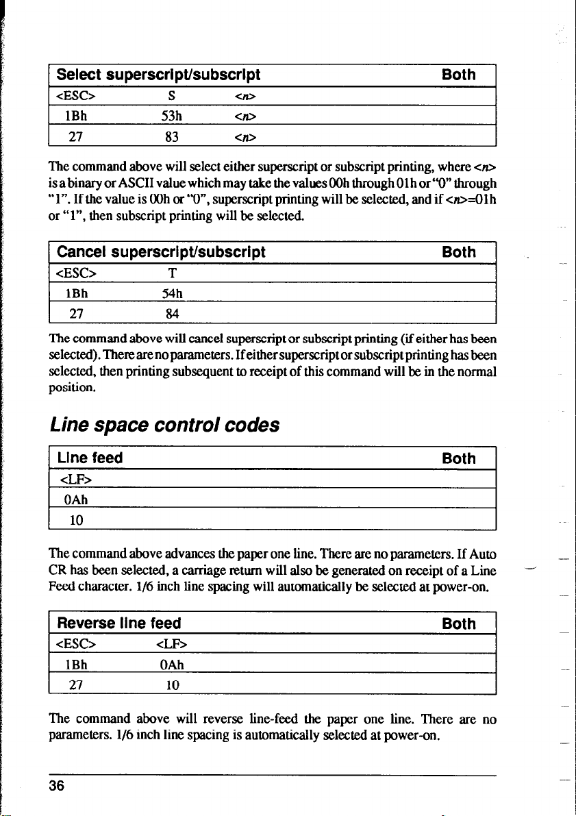

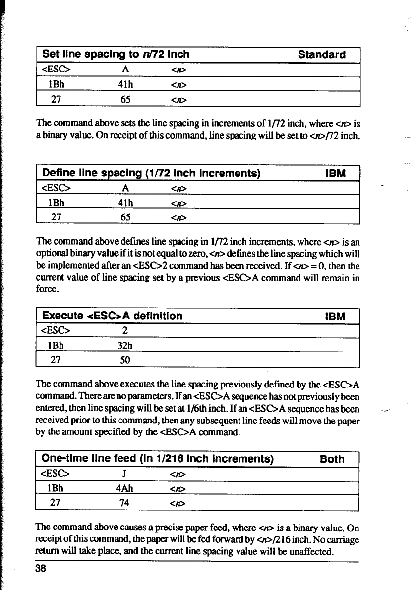

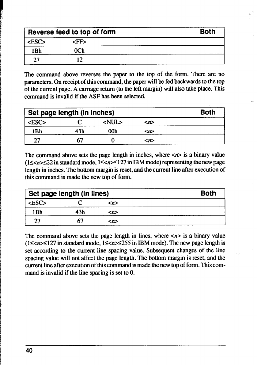
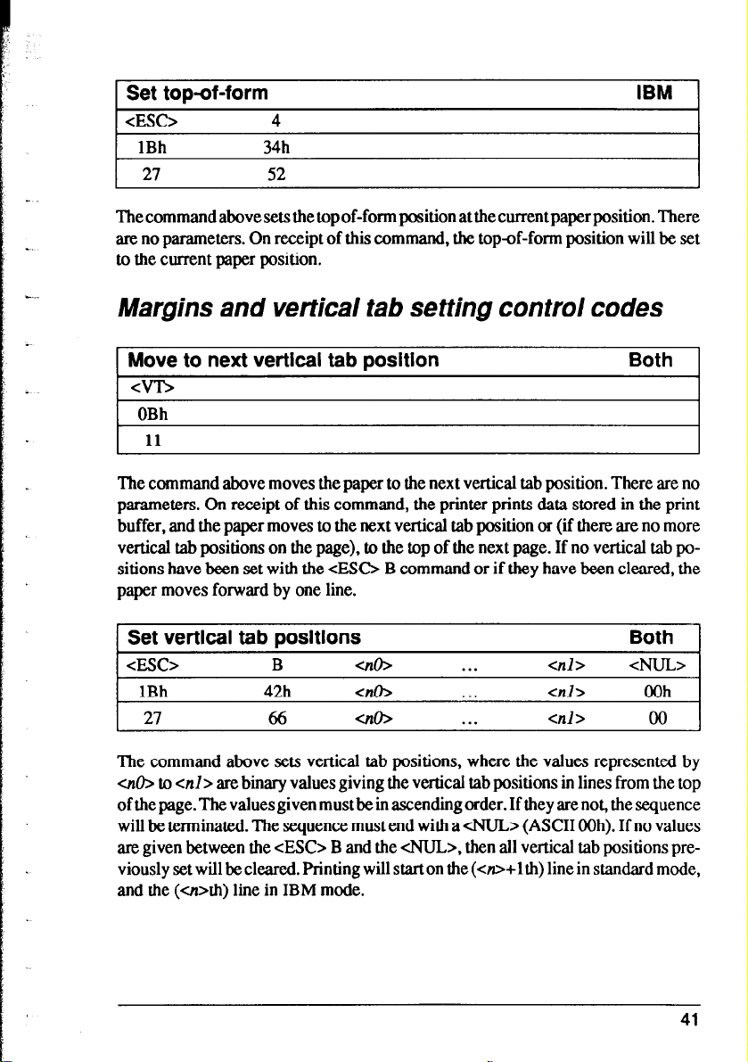


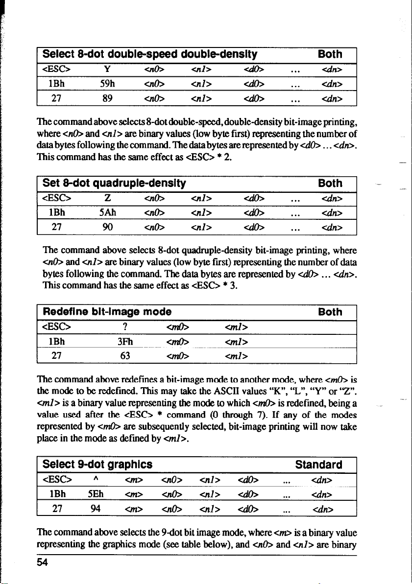


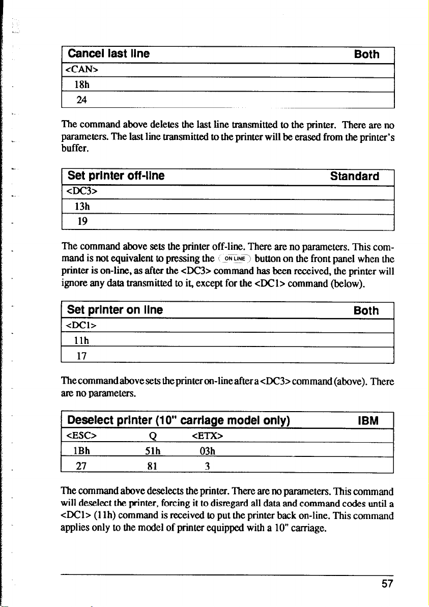


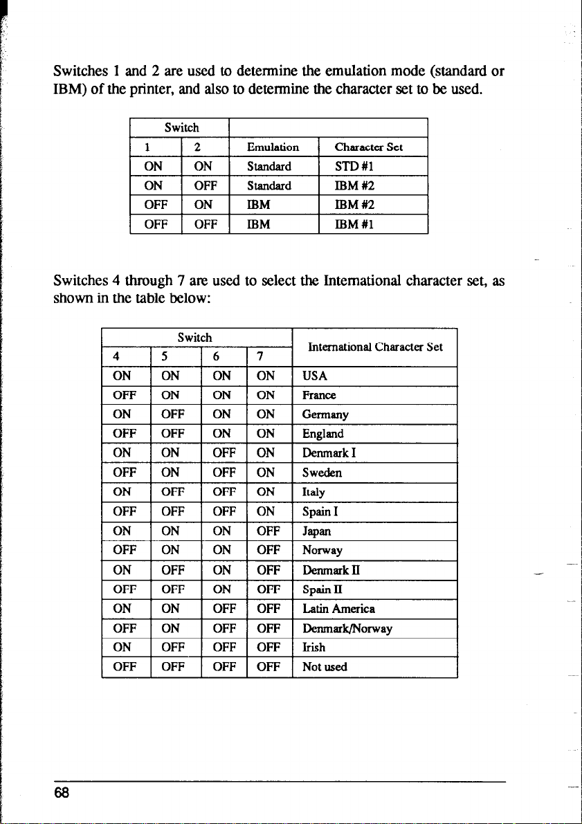


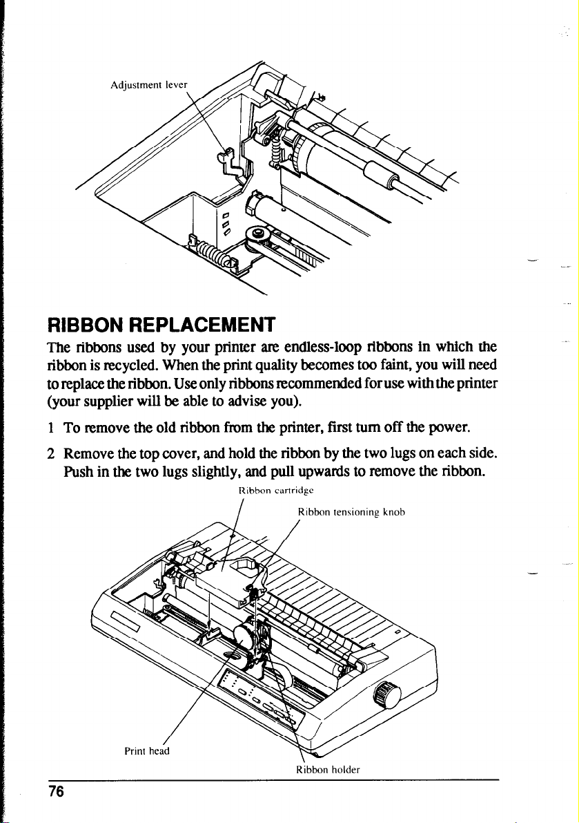


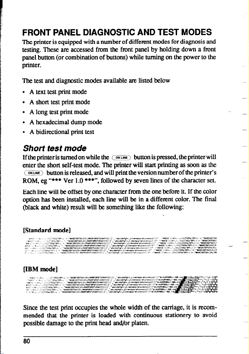


 Loading...