

Page 1
XB24-200
XB24-250
MULTI-FONT
USERS MANUAL
NOT INTENDED FOR SALE
Page 2

Radio interference regarding this equipment has been eliminated according to Vfg 1046/1984announced
by the DBP.
DBP has been informed of the introduction of this special equipment and has been granted the right to
examine the whole series.
It is the user’s responsibility to see that his own assembled system is in accordance with the technical
regulations under Vfg 1046/1984.
To conform to PlZ-regulations it is necessary to make all connections to the printer with shielded cable.
‘he equipment may only he opened by qualified service representatives.
Tk above statement applies only to printers marketed in Germany.
Self Declaration
-
-
-
-
Trademark Acknowledgements
IP-128XL, SF-lODMIl/lSDMII, SF-lORMII/l5RMII, PT.lOXM115XM: Star Micronics Co., Ltd.
IBM-PC, PS/2, PC-AT, Proprinter X24E/XL24E, Proprinter X24fXL24, PC-DOS: International
Business Machines Corp.
MS-DOS, Microsoft BASIC: Microsoft Corporation
LQ-S6U10609 LQ-850/1050: Seiko Epson Corp.
NOTICE
l All rights reserved. Reproduction of any part of this manual in any form whatsoever without
STAR’s express~rmissicn is forbidden.
l
The contents of IS manual are subject to change without notice.
l Allefforts havebeenmadetoensuretheaccuracyofthecontentsofthismanualatIhetimeofpress.
However, should any errors be detected, STAR would greatly appreciate being informed of them.
l ‘lhe above notwithstanding, STAR can assume no responsibility for any errors in this manual.
0 Copyright 1991 Star Micronics Co., Ltd.
-
-
- XB24-2001250, XB24-10115, LC24-200, FZ24, LZ24, X24CL, RC-32Z, DC-32Z, IS-IIXL,
-
Page 3
HQW TO USE THIS MANUAL
This manual is organized into eleven chapters. To learn how to make the best
use of your printer you am urged to mad through chapters 2 through 6. The
remaining chapters may be treated as a reference guide for programming
operations, etc. It assumes a degree of acknowledge of the operation of
computers (for instance, it assumes you.know about hexadecimal numbers).
The chapters are as follows:
c..
Chapter 1 - Introduction
..-
c
This chapter indicates the some features of the printer, the names and those
functions of the printer components, and the actual example of font style.
Chapter 2 - Setting up the printer
This chapter explains how to get the printer unpacked and set up. Read this
chapter before you do anything else.
Chapter 3 - Optional accessories
This chapter explains the optional accessories with your printer, and how to
install them.
Chapter 4 - Paper installation and use
This chapter describes instructions for printing such as selecting paper types,
adjusting the printing gap, and installing paper.
Chapter 5 - Control panel operations
There am a number of contmls on the front panel which perform various
functions related to paper handling, print modes and font selection.
After getting set up, read this chapter and try out the procedures in it to find
out how the printer works.
Page 4
Chapter 6 - Default settings
This chapter explains how to set the Electronic DIP Switch (EDS) mode to
make system settings on the printer.
Chapter 7 - Printer control commands
This chapter explains the different emulations provided by your printer, and
the software commands used to drive it. This section is of use if you are
writing or modifying programs to take advantage of the printer’s features.
Chapter 8 -
Download characters
This chapter explains the procedures to create your own characters.
Chapter 9 - MS-DOS and your printer
Since the PSL? or PC-AT family of computers running under MS-DOS is
currently the most popular configuration of microcomputer, we have included
a few hints and tips to help you use your printer with such systems.
Since virtually all PCs are sold with a Microsoft BASIC interpreter, we have
alsoincludedsomehints,andasampleprogmminthislanguagetodemonstrate
the capabilities of the printer.
Chapter 10 - Troubleshooting and maintenance
This section gives a checklist of points to check if your printer is not working
in the expected way. It also includes details of some routine maintenance
operations you can carry out yourself. It is not, however, a complete service
manual. Call a qualified service engineer if you am unsure of your ability to
carry out any maintenance or servicing operations.
Chapter 11 - Reference
-
- -
-
This section gives some reference of your printer, such as specifications of
your primer, the pinout of interface connector, the character tables.
The character table charts give the different character sets available.
Page 5
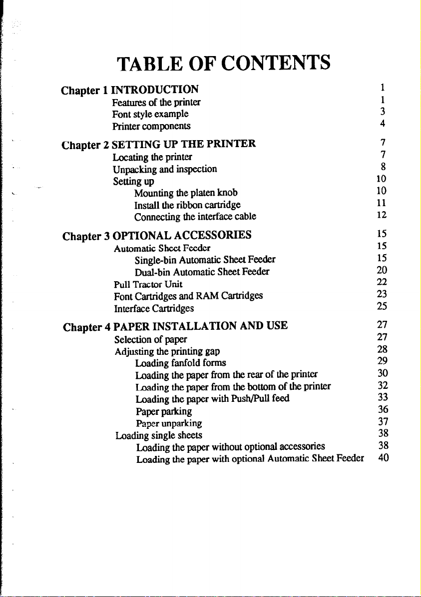
TABLE OF CONTENTS
Chapter 1 INTRODUCTION
Features of the printer
Font style example
Printer components
Chapter 2 SETTING UP THE PRINTER
Locating the printer
Unpacking and inspection
Setting up
Mounting the platen knob
Install the ribbon cartridge
Connecting the interface cable
Chapter 3 OPTIONAL ACCESSORIES
Automatic Sheet Feeder
Single-bin Automatic Sheet Feeder
Dual-bin Automatic Sheet Feeder
Pull Tractor Unit
Font Cartridges and RAM Cartridges
Interface Cartridges
Chapter 4 PAPER INSTALLATION AND USE
Selection of paper
Adjusting the printing gap
Loading fanfold forms
Loading the paper from the rear of the printer
Loading the paper from the bottom of the printer
Loading the paper with Push/Pull feed
Paper parking
Paper unparking
Loading single sheets
Loading the paper without optional accessories
Loading the paper with optional Automatic Sheet Feeder
7
7
8
10
10
11
12
15
15
15
20
22
23
25
27
27
28
29
30
32
33
36
37
38
38
40
Page 6
Chapter 5 CONTROL PANEL OPERATIONS
Bottoms and indicators
ON LINE button
PAPER FEED button
SET/EJECT/PARK button
PITCH button
FONT button
Power-up functions
Short test mode
Long test mode
Print area test mode
Pitch lock mode
Font lock mode
Font and Pitch lock mode
Hexadecimal dump
Switch combination functions
Form feed
Top of form
Forward micro-feed
Reverse micro-feed
Changing the auto loading value
Clearing the buffer/All reset
Selecting the print color
Selecting the ASF bin number
Store macro definition
43
43
44
44
45
45
46
47
47
48
49
49
49
49
50
52
52
52
53
53
53
54
54
55
56
-
_-
-
Chapter 6 DEFAULT SETTINGS
How to set the EDS mode
Functions of the EDS settings
Command parameters
Font parameters
Character parameters
Style parameters
Layout parameters
Forms parameters
Other parameters
Dot Adjustment mode
57
57 v
58
60
61
63
65
66
68
70
71
Page 7
Chapter 7 PRINTER CONTROL COMMANDS
Font control commands
Character set commands
Character size and pitch commands
Vertical position commands
Horizontal position commands
Graphics commands
Download character commands
Color selection commands
Other printer commands
73
74
81
84
90
97
103
107
112
113
Chapter 8 DOWNLOAD CHARACTERS
Defining your own characters with Standard mode
Assigning the character data
Assigning a value of character space
Sample program
Defining your own characters with IBM mode
Assigning the download character set
Assigning the character dot pattern
Assigning the Index Table data
Sample program
Chapter 9 MS-DOS AND YOUR PRINTER
!nstalling application software with your printer
Embedding printer commands
Programming the printer with DOS commands
Programming with BASIC
Chapter lOTROUBLESHOOTING AND MAINTENANCE
Troubleshooting
Power supply
Printing
Paper feeding
Maintenance
Replacing the print head
117
117
118
119
120
122
122
123
125
126
129
129
130
132
135
143
143
144
144
146
149
149
Page 8
Chapter 11 REFERENCE
Specifications
Pinout of interface connector
Parallel interface
Serial interface
charactersets
!3tandardcbaracterset#2
International charactex sets
IBM character set #2
Character set#l
IBM special character set
Proportional spacing table
151
151
155
155
156
157
158
160
161
168 169
170 -
-
INDEX
COMMAND SUMMARY
183
187
Page 9
Chapter 1
This printer has a full complement of features, making it an excellent partner
c
L
for a personal computer. It supports the Epson/IBM printer commands and
character sets, enabling it to print just about anything your computer can
generate, both text and graphics.
- L FEATURES OF THE PRINTER
Some of main features are the following:
l Versatile paper handling
Single sheets, fanfold forms, and multi-part forms (up to 5-ply) are all
accepted, andyoucanuseeitherpush/pulltractororfrictionfeed. (Youcan
load fanfold forms from the rear with internal push tractor, or fanfold
forms and multi-part forms from the bottom with optional pull tractor.) A
special feature enables you to keep fanfold forms parked in readiness while
printing on other paper.
l Six bright colors
Magenta, cyan, violet, yellow, orange and green add a color dimension to
your printed output by the optional color ribbon.
lNTRODUCT/ON
L.
. .
L
L.
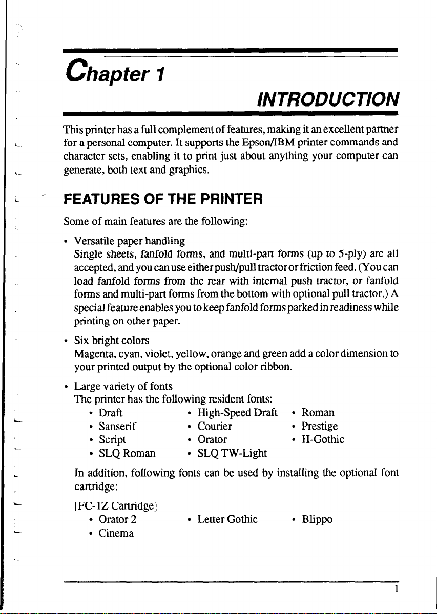
l Large variety of fonts
The printer has the following resident fonts:
l Draft
l Sanserif l Courier l Prestige
’ script
l SLQ Roman
l High-Speed Draft l Roman
l Orator
l SLQ TW-Light
l H-Gothic
In addition, following fonts can be used by installing the optional font
cartridge:
[FC- 1Z Cartridge]
l Orator 2
l Letter Gothic
l Blippo
. Cinema
1
Page 10
[FC-2Z Cartridge]
l OCR-B
l UPC/EAN
[FC-3Z Cartridge]
l TW-Light
[FC-4Z Cartridge]
l Russian
[FC-SZ Cartridge]
l Old Style
l OCR-A
l Orane
l Firenze
l CODE 39
[FC- 1OZ Cartridge]
l SLQ Script
l Extensive software support
Since it is compatible with the Epson and IBM printers, it works with any
software that supports those printers. That includes most word-processing
and graphics programs, spread-sheets, and integrated software packages.
l Easy operation
Indicator displays and beep tones provide immediate, easy to understand
feedback when you press the buttons on the control panel. The five buttons
can operate in combinations to perform a surprising variety of functions,
including micro-alignment.
l Easy care and maintenance
The ribbon cartridge can be replaced in seconds the print head in a few
minutes.
-
-
-
-.
Page 11

FONT STYLE EXAMPLE
yourprintercanprint.
1111111111111111111111111111111111111111
1111111111111111111111111
Thefollowingexampleshowsthemanyfontstyles
b‘.
Draft
HS-Draft
Roman
Sanserif
Courier
Prestige
.-
Script
OCR-B
OCR-A
Orator
Orator-2
TW-Light
Letter Gothic
Blippo
H-Gothic
Orane
Cinema
CODE 39
LJPC/EAN
Old Style
Firenze
SLQ Roman
SLQ TW-Light
SLQ Script
'I23456789 ABCDEFGHIJK abcdefghijk
1 234.55’7@3 f>B[z[:l E Fc[; I-/ 1: J t<
&)t:,::~:-Jty: 1” g/y i j I<,,
123456789 ABCDEFGHIJK abcdefghijk
123456789 ABCDEFGHIJK abcdefghijk
123456789 ABCDEFGHIJK abcdefghijk
123456789 ABCDEFGHIJK abcdefghijk
1234567&g ABCDEFGHIJK abcd&gWk
123456789 ABCDEFGHIJK abcdefghijk
123456789 ABCDEFGHIJK abcdefghijk
123456789 ABCDEFGHIJK ABCDEFGHIJK
123456789 ABCDEFGHIJK abcdefshijk
123456789 ABCDEFGHIJK abcdefghijk
123456789 ABCDEFGHIJK abcdefghijk
123456789 ABCDEFGHIJK abcdefghijk
123456789 ABCDEFGHIJK abcdefghijk
123456789 A8CDEFGHlJK abcdefghijk
123456789 ABCDEFGHIJK abcdefghijk
II
Ml 111111111111 Hill
II
‘23456789 ~*34~6’891l11 11111 1111111 I III 111111
123456789 A3tl%EWQ~JJ~ abcbafghtfk
123456389 ABCDEfGliI~K abcdePyhijk
123456789 ABCDEFGHIJK abcdefghijk
123456789 ABCDEFGHIJK abcdefghijk
123456789 ABCDEFGHIJK abcde&h.i&
Page 12
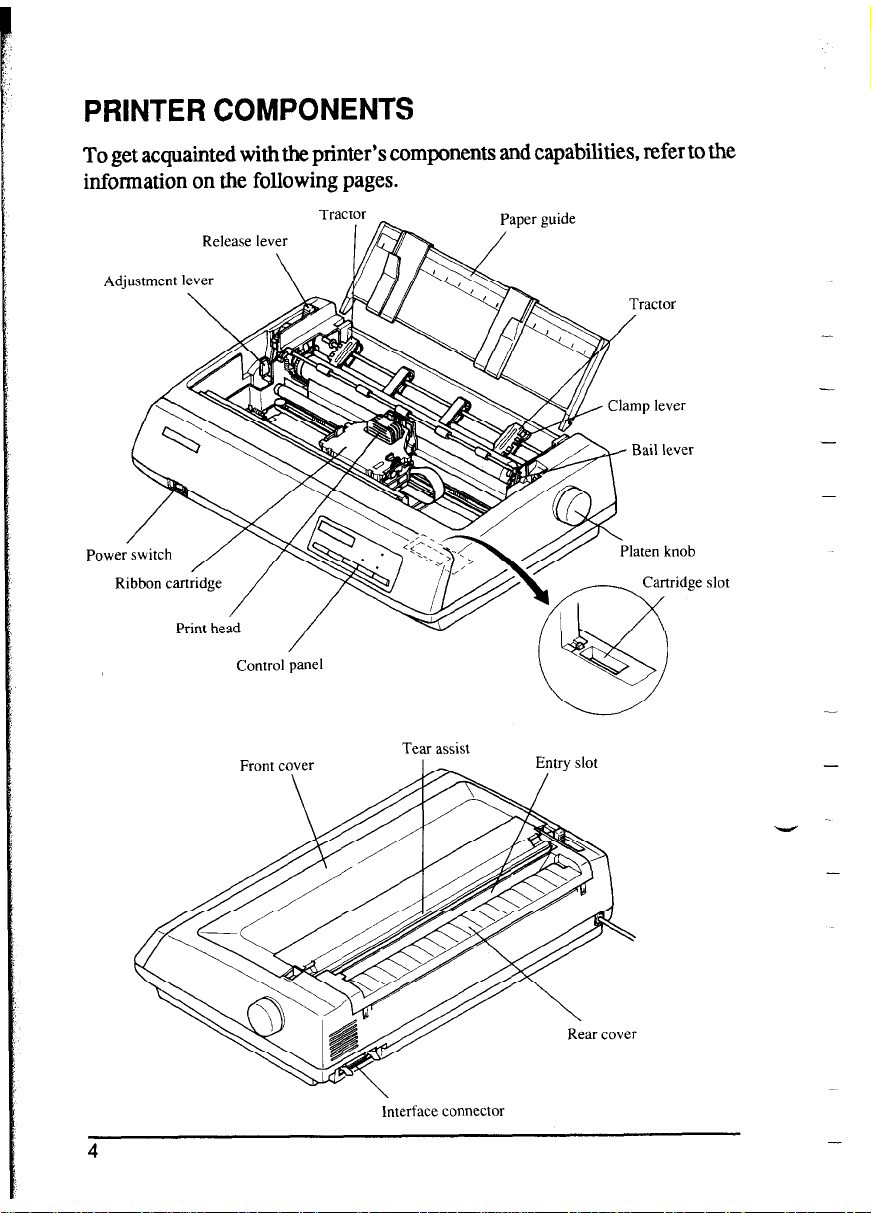
PRINTER COMPONENTS
To get acquainted with the printer’s components and capabilities, refer to the
information on the following pages.
Tractor
Adjustment lever
Control panel
,er guide
-
-
-
Tear assist
Interface connector
-
Page 13
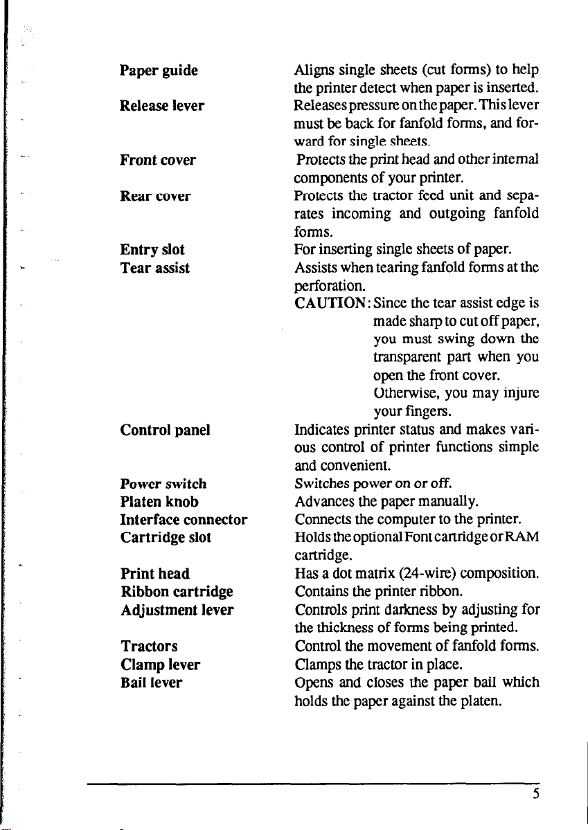
Paper guide
Release lever
Front cover
Rear cover
Entry slot
Tear assist
Control panel
Power switch
Platen knob
Interface connector
Cartridge slot
Print head
Ribbon cartridge
Adjustment lever
Tractors
Clamp lever
Bail lever
Aligns single sheets (cut forms) to help
the printer detect when paper is inserted.
Releases pressure on the paper. This lever
must be back for fanfold forms, and forward for single sheets.
Protects the print head and other internal
components of your printer.
Protects the tractor feed unit and separates incoming and outgoing fanfold
forms.
For inserting single sheets of paper.
Assists when tearing fanfold forms at the
perforation.
CAUTION: Since the tear assist edge is
made sharp to cut off paper,
you must swing down the
transparent part when you
open the front cover.
Otherwise, you may injure
your fingers.
Indicates printer status and makes various control of printer functions simple
and convenient.
Switches power on or off.
Advances the paper manually.
Connects the computer to the printer.
Holds the optional Font cartridge or RAM
cartridge.
Has a dot matrix (24-wire) composition.
Contains the printer ribbon.
Controls print darkness by adjusting for
the thickness of forms being printed.
Control the movement of fanfold forms.
Clamps the tractor in place.
Opens and closes the paper bail which
holds the paper against the platen.
5
Page 14

MEMO
-
-
-
-
-
-
V
-
-
Page 15
L.
chapter 2
SETTING UP THE PRINTER
This chapter describes the following procedures to set up your new printer.
If you have optional accessories, refer to chapter 3 after setting up the printer.
l Locating the printer
l Unpacking the carton box
l Mounting the platen knob
l Installing the ribbon cartridge
* Connecting the printer to your computer
LOCATING THE PRINTER
Before you start unpacking and setting up your printer, make sure that you
have a suitable place on which to locate it. By “a suitable place”, we mean:
. A firm, level surface which is fairly vibration-free
l Away from excessive heat (such as direct sunlight, heaters, etc)
l Away from excessive humidity
L...
9 Away from excessive dust
l Supply it with “clean” electricity. Do not connect it to the same circuit as
a large, noise-producing appliance such as a refrigerator.
l Make sure the line voltage is the voltage specified on the printer’s
identification plate.
l To disconnect the printer, the plug has to be disconnected from the wall
socket, which has to be located close to the printer, and easy to access.
l Install the printer where there is sufficient mom for the paper and any paper
being fed in or printed out.
l If you are connecting your printer with a parallel interface, make sure that
the cable is within 2m (6ft) of the printer. AnRS-232 connectionusing the
optional IS-8XL interface cartridge can be made over longer distances.
7
Page 16
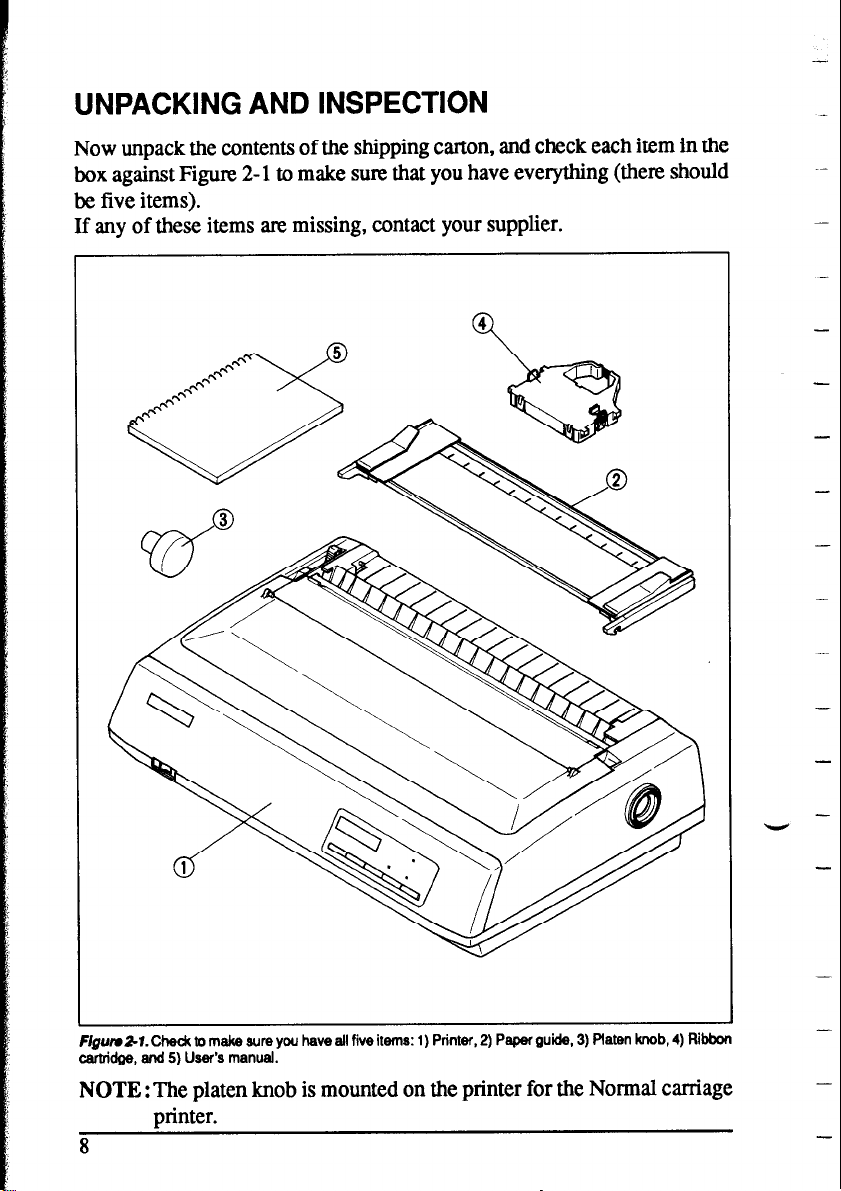
UNPACKING AND INSPECTION
Now unpack the contents of the shipping carton, and check each item in the
box against Figure 2- 1 to make sure that you have everything (there should
be five items).
If any of these items are missing, contact your supplier.
-
-
-
-
F@uui&r. Check to make sure you have all five items: 1) Printer, 2) Paper guide, 3) Platen knob, 4) Ribbon
cartridge, and 5) User’s manual.
NOTE : The platen knob is mounted on the printer for the Normal carriage
minter.
8
-
-
V
-
-
Page 17
The optional accessories which you may have ordered with your printer are:
. Film ribbon ctidge (FZ24)
l Color ribbon cartridge (X24CL)
l Font cartridges (FC series)
l RAM cartridge (RC-32Z, DC-32Z)
l Serial interface cartridge (IS-8XL)
l Buffered parallel interface cartridge (IP- 128XL)
l Automatic sheet feeder (SF-lODMII/lSDMII, SF-1ORMII/15FUvlII)
. PuIl tractor unit (PT-lOXM/lSXM)
For details of the optional accessories, refer to Chapter 3.
9
Page 18
SETTING UP
Place the printer in the desired location, and remove all packing material
from inside the printer cover. This packing material is intended to prevent
damage to the printer while in transit. You will want to keep all the packing
material, along with the printer carton, in case you have to move the printer
to a new location.
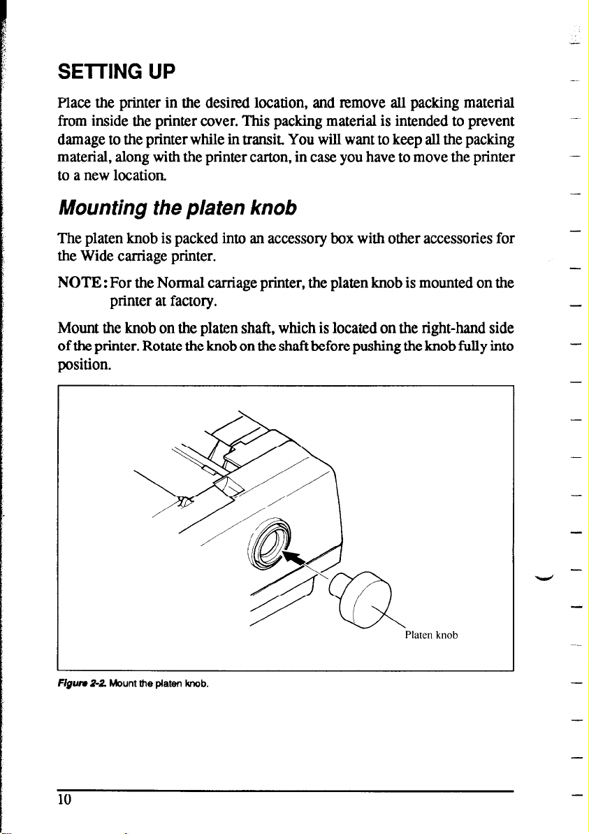
Mounting the platen knob
The platen knob is packed into an accessory box with other accessories for
the Wide carriage printer.
NOTE : For the Normal carriage printer, the platen knob is mounted on the
printer at factory.
-
-
-
Mount the knob on the platen shaft, which is located on the right-hand side
of the printer. Rotate the knob on the shaft before pushing the knob fully into
position.
Platen knob
F/gwv 2-Z Mount the platen knob.
“bd
-
-
-
-
-
-
-
-
10
-
-
Page 19
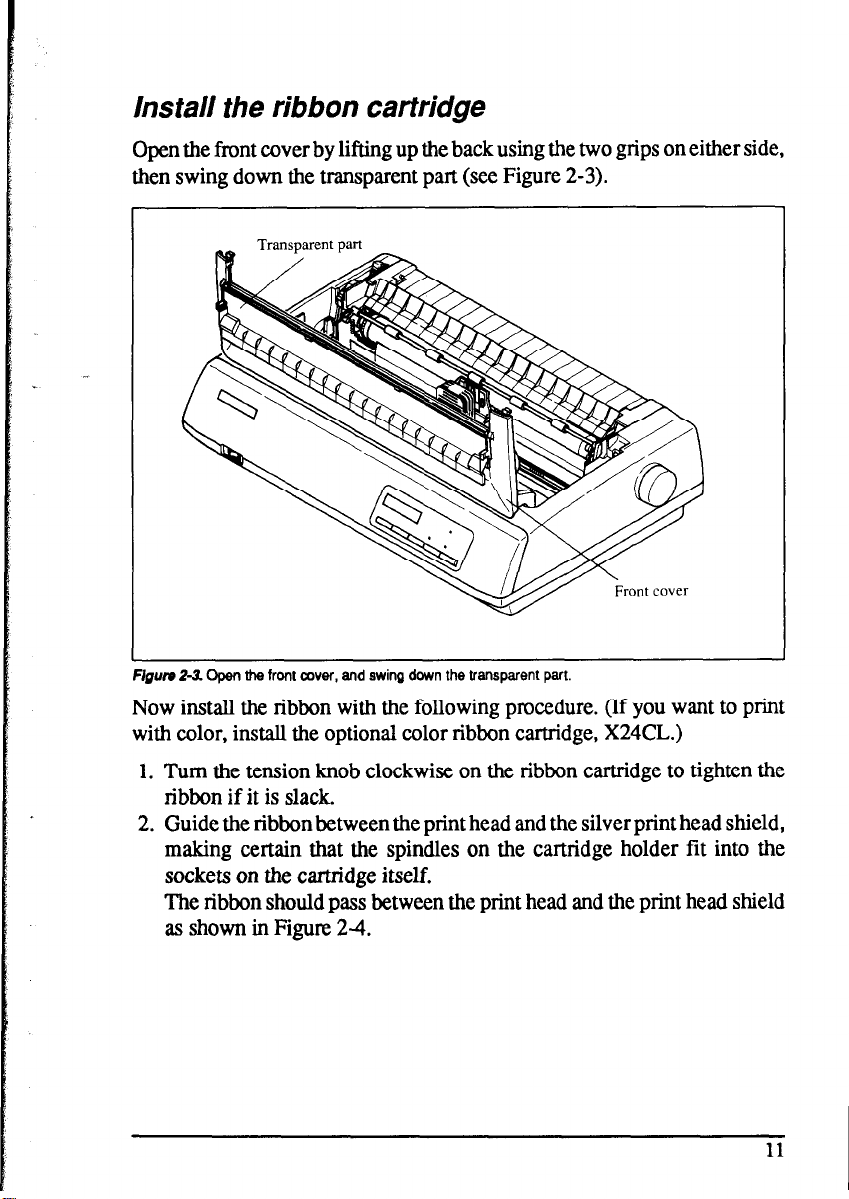
Install the ribbon cartridge
Open the front cover by lifting up the back using the two grips on either side,
then swing down the transparent part (see Figure 2-3).
F/gum 2-3. Open the front cover, and swing down the transparent part.
Now install the ribbon with the following procedure. (If you want to print
with color, install the optional color ribbon cartridge, X24CL.)
1. Turn the tension knob clockwise on the ribbon cartridge to tighten the
ribbon if it is slack.
2. Guide the ribbon between the print head and the silver print head shield,
making certain that the spindles on the cartridge holder fit into the
sockets on the cartridge itself.
The ribbon should pass between the print head and the print head shield
as shown in Figure 24.
11
Page 20
-
shield
/
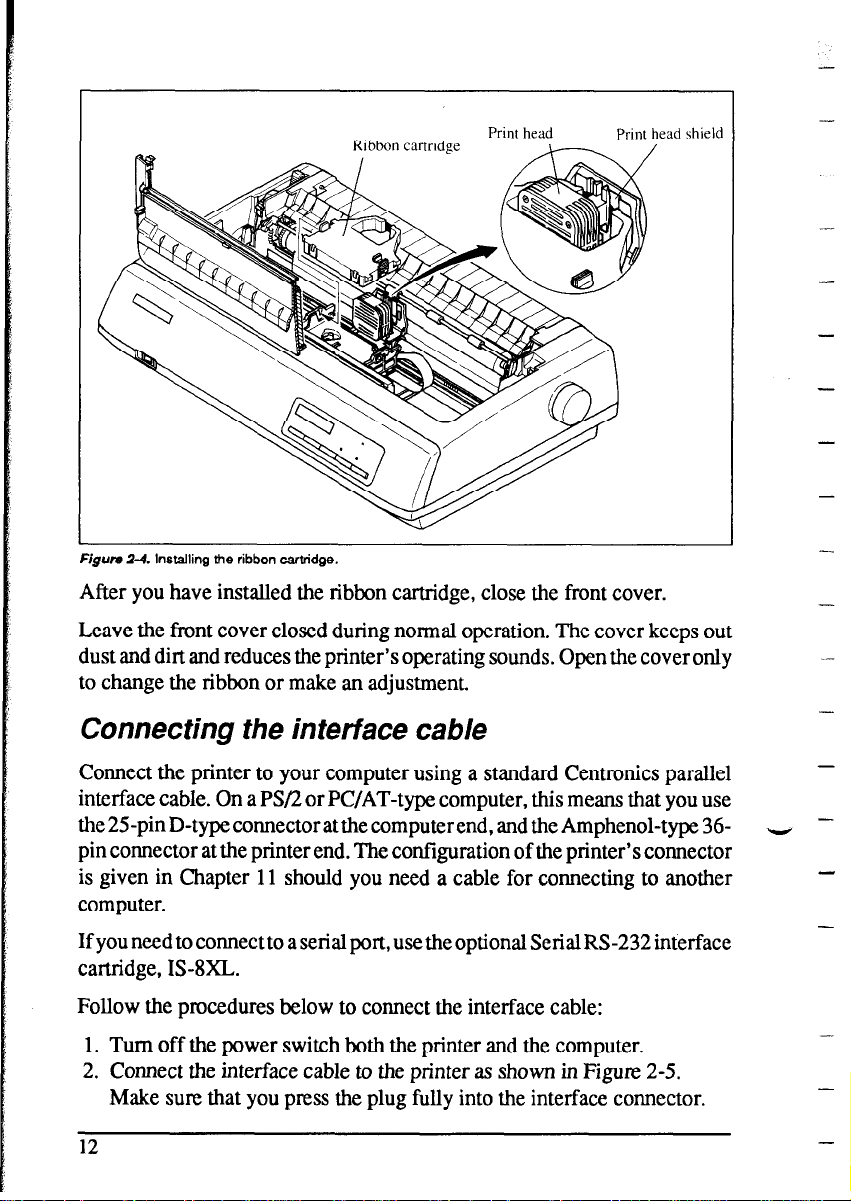
Figufe Z-4. Installing the ribbon cartridge.
Ribbon canridee \-
Print head
Print head
After you have installed the ribbon cartridge, close the front cover.
Leave the front cover closed during normal operation. The cover keeps out
dust and dirt and reduces the printer’s operating sounds. Open the cover only
to change the ribbon or make an adjustment.
-
-
-
-
-
-
Connecting the interface cab/e
Connect the printer to your computer using a standard Centronics parallel
interface cable. On a PS/2 or PC/AT-type computer, this means that you use
the 25pin D-type connector at the computerend, and the Amphenol-type 36pin connector at the printer end. The configuration of the printer’s connector
is given in Chapter 11 should you need a cable for connecting to another
computer.
If you need to connect to a serial port, use the optional Serial RS-232 interface
cartridge, IS-8XL.
Follow the procedures below to connect the interface cable:
1. Turn off the power switch both the printer and the computer.
2. Connect the interface cable to the printer as shown in Figure 2-5.
Make sure that you press the plug fully into the interface connector.
12
-
‘v
-
Page 21
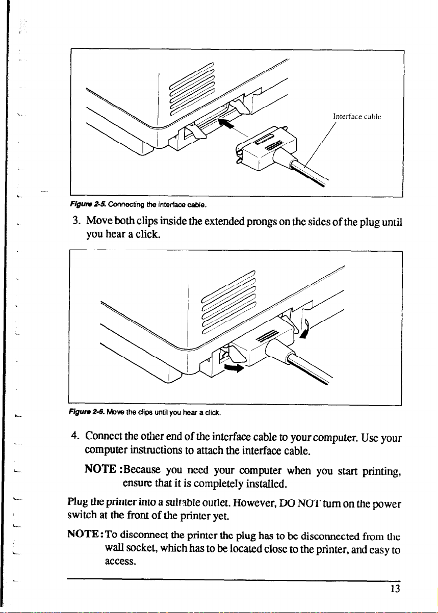
Inierface cable
Fipu Z-5 Connecting
the interface cable.
3. Move both clips inside the extended prongs on the sides of the plug until
you hear a click.
Flguru Z-6. Move the clips until you hear a did.
4. Connect the other end of the interface cable to your computer. Use your
computer instructions to attach the interface cable.
NOTE :Because you need your computer when you start printing,
ensure that it is completely installed.
Plug the printer into a suitable outlet. However, DO NOT turn on the power
switch at the front of the printer yet.
NOTE:To disconnect the printer the plug has to be disconnected from the
wall socket, which has to be located close to the printer, and easy to
access.
13
Page 22
MEMO
-
-
-
-
-
V
-
Page 23
chapter 3
OPTIONAL ACCESSORIES
You can select the following accessories as option.
l Automatic sheet feeder (SF-lODMII/lSDMIJ, SF-lORMW15RMII)
l Pull tractor unit (BT-lOxM/lSXM)
l Font cartridges (FC series)
l RAM cartridge (RC-322, DC-322)
l Serial interface cartridge (IS-8XL)
l Buffered parallel interface cartridge (P-128XL)
This chapter describes how to install these optional accessories.
NOTE : When you install or remove the optional accessories, turn off the
power switch.
AUTOMATIC SHEET FEEDER
You can use the Automatic Sheet Feeder to print on single sheets.
This printer can be used either a Single-bin type or Dual-bin type Automatic
Sheet Feeder.
Single-Bin Automatic Sheet Feeder
(SF- 1 ODMIUI 5DM.u)
The procedure to mount the Single-Bin ASF is:
1. Open the front cover by lifting up the back using the two grips on either
side, then swing down the transparent part (see Figure 3-l).
2. Open the rear cover by lifting up the front using the two grips on either
side, then remove it upward.
If the paper guide is installed, remove it before taking off the rear cover.
3. Move the bail lever on top of the printer forward to open the paper bail.
15
Page 24
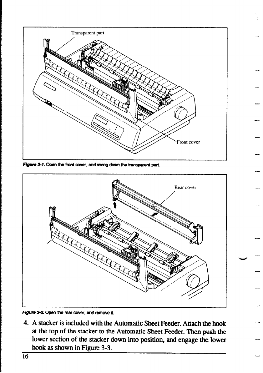
Transparent part
-
4. A stacker is included with the Automatic Sheet Feeder. Attach the hook
at the top of the stacker to the Automatic Sheet Feeder. Then push the
lower section of the stacker down into position, and engage the lower
hook as shown in Figure 3-3.
16
Page 25

QumSZAttachthestadwtothaAutomaticSheetFesder.
5. Tip the Automatic Sheet Feeder forward slightly and put the feeder into
place behind the printer platen roller.
6. Lower the rear side of the Automatic Sheet Feeder and attach it to the
platen shaft.
Automatic Sheet Feeder
Page 26

7. Close the front cover with the transparent part in the open position.
8.
Insert the hopper attachment by hand into the holders on top of the hopper
support section as shown in Figure 3-6.
-
-
-I
-
18
attachment
Page 27

9. Squeeze the sides of the stacker attachments lightly, and insert into the
holders on the front part of the sheet feeder.
Stacker
F/gufw *7. Insert the st8cker attachment.
Now, you can use the ASF by installing the paper stack into the hopper.
(Refer to Chapter 4.)
In addition, you can feed a sheet of paper manually by inserting into the slot
at the front of ASF roller as shown in Figure 3-8.
Figwu 36 insert a sheet of paper to feed manually.
NOTE : Set the paper guide and rear cover aside carefully after they have
been removed from the printer. Reverse the procedure described
above when removing the Automatic Sheet Feeder.
19
Page 28

Dual-Bin Automatic Sheet Feeder
(SF- I ORMIUISRMII)
The procedure to mount the Dual-Bin ASF is:
1. Open the front cover by lifting up the back using the two grips on either
side, then swing down the transparent part (see Figure 3-l).
2. Open the rear cover by lifting up the front using the two grips on either
side, then remove it upward.
If the paper guide is installed, remove it before taking off the rear cover.
3. Move the bail lever on top of the printer forward to open the paper bail.
4. A stacker is included with the Automatic Sheet Feeder. Attach the hook
at the top of the stacker to the Automatic Sheet Feeder. Then push the
lower section of the stacker down into position, and engage the lower
hook as shown in Figure 3-9.
Figure 3-9. Attach the stacker to the Automatic Sheet Feeder.
5. Tip the Automatic Sheet Feeder forward slightly and put the feeder into
place behind the printer platen roller.
6. Lower the rear side of the Automatic Sheet Feeder and attach it to the
platen shaft.
7. Close the front cover with the transparent part in the open position.
8. Attach the clear plastic paper supports between the left and right paper
guides of the hopper bins and the stacker.
-
-
Page 29

Figure 310. Attach the dear plastic paper supports to the Automatic Sheet Feeder.
Now, you can use the ASF by installing the paper stack into the bin. (Refer
to Chapter 4.)
In addition, you can feed a sheet of paper manually by inserting into the slot
at the front of ASF bin #l as shown in Figure 3-l 1.
Figure 311. You can insert a sheet of paper to th+ font slot.
NOTE : Set the paper guide and rear cover aside carefully after they have
been removed from the printer. Reverse the procedure described
above when removing the Automatic Sheet Feeder.
21
Page 30

PULL TRACTOR UNIT (PT-1 OXM/15XM)
You can use the Pull Tractor Unit to print on fanfold forms or multi-part
forms.
The procedure to mount the FWl Tractor Unit is:
1. Open the front cover by lifting up the back using the two grips on either
side, then swing down the transparent part (see Figure 3-l).
2. Open the rear cover by lifting up the front using the two grips on either
side, then remove it upward.
If the paper guide is installed, remove it before taking off the rear cover.
3. Move the bail lever on top of the printer forward to open the paper bail.
4. Squeeze the sides of the paper supports lightly, and insert into the holes
on both side of the F%ll Tractor Unit as shown in Figure 3- 12.
-
-
Hgum 3-12. Mount the paper support A and B onto the Pull Tractor Unit.
5. Fit the mounting brackets of the pull Tractor Unit onto the shaft of the
printer mechanism, tilting the Pull Tractor Unit slightly backward.
6. Secure the FW Tractor Unit firmly by lowering it into position, as shown
in Figure 3- 13.
7. Close the front cover with the transparent part in the open position.
22
-
V
-.
-
Page 31

I
Figure 3-13. Mount the Pull Tractor Unit onto the printer.
NOTE : Set the paper guide and rear cover aside carefully after they have
been removed from the printer. Reverse the procedure described
above when removing the Pull Tractor Unit.
FONT CARTRIDGES AND RAM CARTRIDGES
This printer has seven built-in LQ fonts, and a 29 K-byte (76 K-byte for wide
carriage type printer) printing buffer.
You can add the following optional fonts or expand the printing buffer by
installing optional cartridges (Font Cartridge or RAM Cartridge).
[FC- 1Z Cartridge]
l Orator 2
l Cinema
[FC-2Z Cartridge]
l OCR-B
l UPC/EAN
[FC-3Z Cartridge]
l TW-Light
l Letter Gothic
l OCR-A
l Orane
l Blippo
l CODE 39
23
Page 32

[FC4Z Cartridge]
l Russian
[FC-SZ Cartridge]
l Old Style
l Firenze
[FC- 1OZ Cartridge]
l SLQ Script
To install or change a cartridge, follow the procedure below.
1. Turn off the power switch at the front of the printer, and open the front
cover.
Swing down the transparent part (see Figure 3-l).
2. Remove the connector cover at the right side of the printer.
3. Rush out the cap from the connector cover.
NOTE:Keep this cap in a safe place.
Cartridge
-
._
cover
Flgurr 514. Slide the cartridge intO the sbt with the power switch off.
4. Install the connector cover into the printer.
5. Insert the cartridge into the slot of the connector cover, and slide it all the
way in.
NOTE:Remount the cap on the connector cover if you do not use the
optional cartridge.
24
-
Y
Page 33

INTERFACE CARTRIDGES
You can use the Serial RS-232 Interface with the optional Serial Interface
Cartridge (ISgXL), or extend the print buffer by installing the optional
Buffered ParaIlel Interface Cartridge (IP-128XL), instead of the Standard
Interface Cartridge.
If you want to use the Serial Interface Cartridge, set the DIP switches on the
board before instalI it to the printer.
1. Turn off the power switch and disconnect the power cord from the power
soufce.
2. Disconnect the interface cable if attached.
3. Compress the projected parts on the right and left, and pull the Standard
Interface Cartridge to remove it from the printer.
Figum 315. Remove the Standard Interface Cartridge from the printer.
4. Insert the optional Interface Cartridge securely into place.
If it is not fuIIy inserted, the printer will not properly print.
5. Connect the interface cable to the connector.
NOTE: Store the removed Interface Cartridge in a safe place.
25
Page 34

DIP Switch Functions on The Serial Interface
Cartridge
It is necessary to make compatible the data transfer conditions between the
computer and the serial interface board with the DIP switch settings on the
serial interface board.
Following table shows the functions of the DIP switches on the Serial
Interface Cartridge.
switch
1 Data length
H
Parity condition (Refer below)
Data Protocol
Parity condition
Transfer speed
(Refer below)
CRefer below)
@efer below) LData pro
I
[Transfer speed]
[Parity condition]
1 Switch 2 1 Switch 5 (
I
I
tocol]
I
1 Switch 3 Switch 4 Protocol
I
ON
ON OFF
OFF ON
ON DTR
Condition
XON/XOFF
ETX/ACK
26
Page 35

chapter 4
PAPER INSTALLATIONAND USE
This chapter describes instructions forprinting such as selecting paper types,
adjusting the printing gap, and installing paper.
SELECTION OF PAPER
.-
L
Your printer accepts any of the following papers:
l Single sheets (cut forms) and stationary
Use the friction feed or the optional Automatic Sheet Feeder.
l Fanfold forms
Fanfold forms have holes along the sides and perforations between the
sheets. They are also called sprocket forms, punched forms, or just plain
“computer paper”.
Printing on or near the perforations of continuous fanfold forms may
reduce printing quality, misalign the fanfold forms, or cause a paper jam.
It is recommended not to print within an area of one inch before and after
the perforations.
l Multi-part forms
You can use multi-part forms that have up to five parts including the
original when the Multi-part mode is selected with the EDS setting. (For
details, please refer to Chapter 6.)
Use pressure sensitive multi-part forms with both side edges glued and a
difference in thickness of 0.05mm or less between the side edges.
It is recommended to use the bottom feed with the optional Pull Tractor
Unit to get fine alignment.
i-.
NOTE : Care should be taken in color printing with continuous multi-part
forms. Side edges of paper might be damaged.
l Preprinted forms
27
Page 36

Figure 4-l shows the recommended print area for each type of papers.
Fanfold forma
(*X0 mm for Push Feed)
Figum CT. Racornmandad print area for acceptable papwa.
Single sheets
ADJUSTING THE PRINTING GAP
The distance between the print head and the platen can be adjusted to
accommodate different paperthicknesses. To make this adjustment, open the
front cover. The adjustment lever is located at the left side of the printer
mechanism. Pushing the adjustment lever backwards narrows the gap;
pulling it forwards widens the gap.
1
-
-
There are seven positions, and you can feel the lever clicking into each
position. The second position from the rear (marked with “9”) is the one most
commonly used for single sheets of paper.
Try different positions until you get the best printing results.
NOTE : Printing with an inappropriate gap may drastically shorten the life
of the print head.
28
-~
I
-
Page 37

Ad,justment lever
F@m 4-2 Location of the adjustment lever.
The following table provides the recommended lever positions for each
paper types as a reference.
40-58
40-58
40-58
0.18
0.24
0.30
- 0.25
- 0.30
- 0.35
3rd or 4th
4th or 5th
5th or 6th
LOADING FANFOLD FORMS
This printer accepts fanfold forms up to 10” wide for the normal carriage
printer, and up to 16” wide for the wide carriage printer.
You can load fanfold paper with the following three ways:
l Push feed with internal tractor unit
l Bottom feed with optional Fkll Tractor Unit
l Push/Pull feed with internal tractor unit and the optional Pull Tractor
Unit.
This section will take you through the procedures for loading, parking and
unparking fanfold forms.
Page 38

Loading the paper from the rear of the printer
(Push feed)
You can load the fanfold paper with the internal push tractor unit.
1. Place a stack of fanfold paper behind and at least one page-length below
the printer.
2. Turn the printer’s power OFF.
3. Push the mleaseleverbackward. This has the effect of releasing the paper
from the platen roller, and engaging the tractor feed.
4. Remove the paper guide and put it aside for the moment.
5. Open the transparent part of the front cover, and the rear cover using the
two grips on either side, as in Figure 4-3.
-
-
-
Release lever
Figurn 4-3 Opening the rear cover.
Rear cover
6. Pass the paper between the printer case and the rear cover.
7. With the tractor covers open, mount the paper by aligning holes with the
pins on the tractor unit.
8. Adjust the spacing of the tractor units by sliding them along the bar, using
the clamp lever at the back of each unit to release and lock them in
position. When the clamp lever is up, the unit is released, and when it is
down, the unit is locked.
-
-
-
30
Page 39

Tractor cover
Figun 4-4. Mount the fanfold paper over the tractor units.
Clamp lever
9. Now close the tractor covers, again making sure that the paper holes are
aligned with the pins on the tractor units. If they are not aligned properly,
you will have problems with paper feeding, possibly resulting in tearing
and jamming of the paper.
10. Turn on the power using the switch located at the front of the printer. The
printer will beep, indicating that the paper is not yet fully loaded. The
“PAPER OUT” message will also flash to confirm this.
11. Now press the [ 8t,Z&PT I button. The paper will be fed and adjusted
past the print head to a position ready for printing.
12. If you want to set the paper to a different position, set the printer off-line
by pressing the I ON LINE
1 button, then set the paper by using the
micro-feed function. (For details, refer to Chapter 5.)
13. Close the rear cover and the transparent part of the front cover, then
mount the paper guide in the horizontal position shown in Figure 4-5, so
that it will separate the printed from the unprinted paper.
31
Page 40

FcgUrr 4-5. Mounting the paper guide for fanfold forms.
Loading the paper from the bottom of the printer
You can load the fanfold paper from the bottom of the printer with the
optional Pull Tractor Unit.
1. Install the optional Pull Tractor Unit as described in Chapter 3.
-
-
-
F/gum 4-6. Install the optional Pull Tractor Unit.
32
Page 41

2. With the tractor covers open, mount the paper from the bottom of the
printer, by aligning holes with the pins on the tractor unit.
fVgum 47. Mount the fanfold paper from the bottum of the printer.
3. Adjust the spacing of the tractor units by sliding them along the bar, using
the clamp lever at the back of each unit to release and lock them in
position. When the lever is up, the unit is released, and when it is down,
the unit is locked.
4. Now close the tractor covets, again making sure that the paper holes are
aligned with the pins on the tractor units. If they are not aligned properly,
you will have problems with paper feeding, possibly resulting in tearing
and jamming of the paper.
Loading the paper with Push/pull feed
You can load the fanfold paper with Push/Pull feed by using both the internal
push tractor unit and the optional Pull Tractor Unit.
1. Place a stack of fanfold paper behind and at least one page-length below
the printer.
2. Turn the printer’s power OFF.
3. Push the releaseleverbackward. This has the effect of releasing the paper
from the platen roller, and engaging the tractor feed.
33
Page 42

-
4. Open the transparent part of the front cover, and remove the paper guide
and the rear cover.
5. With the tractor covers open, mount the paper by aligning holes with the
pins on the tractor unit.
6. Adjust the spacing of the tractor units by sliding them along the bar, using
the clamp lever at the back of each unit to release and lock them in
position. When the clamp lever is up, the unit is released, and when it is
down, the unit is locked.
7. Now close the tractor covers, again making sum that the paper holes are
aligned with the pins on the tractor units. If they am not aligned properly,
you will have problems with paper feeding, possibly resulting in tearing
and jamming of the paper.
Release lever
-
-
-
-
-
Figum &I Mount the fanfold paper over be internal tractor units.
8. Turn on the power using the switch located at the front of the printer. The
printer will beep, indicating that the paper is not yet fully loaded. The
“PAPER OUT” message will also flash to confirm this.
9. Now press the lBt,%!SEo ’ 7 button. The paper will be fed past the print
head.
10. Turn off the power, and install the optional Pull Tractor Unit as described
in Chapter 3.
11. With the optional tractor covers open, turn the platen knob clockwise to
mount the paper by aligning holes with the pins on the optional tractor
unit.
34
-
-
-
-
Page 43

Clamp lever
ractor cover
Flgwv +o. Mount the hfold paper to the Pull Trader Unit by turning the platen knob.
12. Adjust the spacing of the optional tractor units by sliding them along the
bar, using the clamp lever at the back of each unit to release and lock them
in position. When the lever is up, the unit is released, and when it is down,
the unit is locked.
13. Now close the tractor covers, again making sure that the paper holes are
aligned with the pins on the optional tractor units. If they are not aligned
properly, you will have problems with paper feeding, possibly resulting
in tearing and jamming of the paper.
14. Remove the lever stopper from the slot of the release lever as shown in
Flgure 4-10.
15. Set the release lever to the ‘Q” position, and turn the platen knob
clockwise to tighten the paper if it is slack.
35
Page 44

Lever stopper
Platen knob
Figum d-70. Remove the lever stopper, and tighten the paper.
16. Push the release lever backward, and remount the lever stopper to the
original position.
Paper parking
After loading fanfold paper with Push feed mode, you do not have to unload it when you want to print on a single sheet. The printer will “park” it for you
if you follow the procedure below.
-
-
-
-
-
-
1. To begin paper parking, start with power ON, fanfold paper loaded in
printing position, and the release lever backward.
2. Press the [ ON LINE 1 button on the control panel to set the printer offline. ON LINE indicator will turn off.
3. Tear off the printed fonn at the last perforation, leaving not more than
about half a page showing above the front cover. If necessary, press the
1 PAPER FEED 1 button to feed paper forward until a perforation is located
just above the front cover, and tear there.
4. Press the P’ “%PGrl button on the control panel.
The printer w~au~matically feed the fanfold fonn backward until the
paper is completely free of the platen.
5. Move the release lever to the front.
36
V
-
-
-
-
-
Page 45

Release lever
guide
aper
F/gum 4-71. Tear off the printed fanfotd paper.
6.
Mount the paper guide in the upright position.
Now you canload single sheets. The fanfold paper remains parked at the back
of the printer.
NOTE : You cannot park the fanfold paper if you have loaded it using the
optional Pull Tractor Unit.
Paper unparking
When you want to resume using fanfold paper, the procedure is as follows.
1
Remove all single sheets from the printer.
2.
Mount the paper guide in the horizontal position.
3.
Move the release lever to the backward.
4.
Press the I?=“‘1 button. The printer will automatically feed the
parked fanfold paper back into position for printing.
NOTE : The printer beeps intermittently if you move the release lever while
the paper is loaded.
37
Page 46

LOADING SINGLE SHEETS
This section will take you through the procedures for loading single sheets
of paper.
Loading the paper without optional accessories
If you are using the optional Automatic Sheet Feeder, refer to next section.
1. Place the paper guide in position by inserting the tabs, located on the
bottom of the assembly, into the slots on the rear cover of the printer.
-
Paper guide
F/gum 4-72 Mounti~ the paper guide for single sheets.
2. Adjust the paper guides to match the size of the paper you will be using.
Remember that printing will start some distance from the left-hand edge
of the carriage.
3. Turn on the power using the switch located at the front of the printer. The
printer will beep, indicating that there is no paper in position for printing.
The “PAPER OUT message will also flash to confirm this.
4. Make sure that the release lever is at front position.
If fanfold paper is already mounted in the printer, press the
I”‘?ZZE’T button to park the paper in the off-line state, then move the
release lever forward.
-
-
-
-
-
-
-
-
-
Page 47

5. Place a single sheet between the guides, placing the side on which you
want to print towards the back of the printer. Gently push the paper down
in the guides until you feel it stop.
6. Now press the
m] button. The paper will be fed into the
printer and adjusted past the print head to a position ready for printing.
7. If you want to set the paper to a different position, set the printer off-line
by pressing the I
ON LINE I button, then set the paper position by
using the micro-feed function. (For details, refer to Chapter 5.)
F/gum 4-13. Loading a single sheet.
Page 48

Loading the paper with optional Automatic Sheet
Feeder
If you are not using the optional Automatic Sheet Feeder, refer to the
previous section.
1. Install the optional Automatic Sheet Feeder as described in Chapter 3.
-
--
-
-
-
I
F/gum 411. Install the optional Autmatic Sheet Feeder.
2. Use the printer’s EDS mode to select ASF. (For details, please refer to
Chapter 6.)
3. If fanfold paper has already been loaded in the printer, park the paper
through the rear slot.
4. Full the printer release lever forward to load single sheets.
5. When you am using Single-Bin ASF, pull the paper loading lever forward
to pull the hopper out until it is in position.
In case of the Dual-Bin ASF, pull both pressure bar levers forward to
open the pressure bar.
40
-
- -
-
-
Page 49

Paper loading lever
[Dual-Bin]
lever
[Single-Bin]
f/gum 415. Make ready ID load paper.
6. Adjust the left paper guide to the desired left position by moving it
horizontally in either dinxtion. (Unlock the paper guides by pressing
down on the locking levers in case of Dual-Bin ASF.)
Lock the lefi paper guides in position by moving the locking lever up for
7.
the Dual-Bin ASF.
Figwv 416. Adjust the paper guides to acammdata the width of the paper.
41
Page 50

8. Adjust the right paper guide to accommodate the width of the paper.
.~
The guides should be adjusted to restrict the amount of horizontal play
while allowing the paper to slide up and down freely between the two
paper guides. The ideal distance between paper ream and paper guides is
0.25 mm (0.01”) on both sides at the narrowest part of the paper guides.
9. Fan the paper stack and square it off properly before inserting it into the
Automatic Sheet Feeder.
Flgun 417. FM the paper before inserting into the ASF.
10. Insert the paper stack into the Automatic Sheet Feeder.
The stack should not be more than 15 mm (5/V) equivalent to 150 sheets
of 20 lb paper.
If necessary, remove some sheets. The ASF may not perform satisfac-
torily if it is overloaded.
11. When you am using Single-Bin ASF, push the paper loading lever toward
the back.
In case of the Dual-Bin ASF, push both pressure bar levers toward the
back to “FEED”
-
-
L
Figurr 418.
42
Push the paper loading lever or pressure
-
-
bar levers to hold lhe paper stack.
-
Page 51

chapter 5
CONTROL PANEL OPERATIONS
The control panel buttons can be pressed individually to perform the
operations indicated by their names. Other functions can be achieved by
holding these buttons down when you turn the printer’s power on, or by
pressing the control panel buttons in combination.
This chapter explains all the button and indicator functions.
l Pause printing
l Feed paper (fast and slow, forward and reverse)
l Park fanfold forms
l Set the top-of-form position
l Select the print pitch
l Select a font
l Print test patterns
. Prevent software from changing the panel pitch and font selections
l Print a hexadecimal dump
l Clear the printer’s buffer
l Change the print color
l Store macro deftition
BUTTONS AND INDICATORS
The printer is equipped with five buttons on the control panel. From left to
righttheyare 1 FO,,,T I I
MODE ,
and [ ON LINE 1.
The following is a brief guide to the buttons and indicators on the control
panel.
Figure 5-I. Control panel.
PITCH 1, -),I PAPER FEED 1
Page 52

ON LINE button
_~
The 1 ON LINE 1 button sets the printer on-line and off-line. The status
changes each time you press the button.
When the printer is on-line, it can receive and print data from the computer.
When the printer is off-line, it stops printing and sends the computer a signal
indicating that it cannot accept data.
The printer powers up in the on-line status if paper is loaded. If paper is not
loaded, the printer powers up off-line with the “PAPER OUT” message
blinking. When you load paper, the printer goes on-line.
You will want to press the I ON LINE ] button:
l Before and after any other panel operation
The other panel buttons operate only in the off-line state. Press the
[ ON LINE 1 button to go off-line. After performing the panel
operation(s), press the I ON LINE 1 button again to go back on-line.
l To pause during printing
If you press the I
printing and goes off-line, allowing you to check the printout or change
a control panel setting. Printing resumes when you press the
I ON LINE I button again to go back on-line.
.
To cut fanfold fonns at the end of printing
When you hold the [
push tractor mode, the printer goes off-line and displays the “SHORTTEAR-
OFF” message, then the printer also feeds the paper forward apptoxi- mately two inches forward. This allows you to cut it offjust below the last
line printed.
When you press the I ON LINE 1 button again to go back on-line, the paper feeds backward stopping where you left off.
ON LINE 1 button during printing, the printer stops
ON LINE 1 button down for one second with the
NOTE: This function is valid only when the buffer is empty.
PAPER FEED button
If you press this button while off-line, the paper will feed forward. If you hold
the button down, the printer will perform consecutive line feeds.
If you also press the 1 ON LINE 1 button while you are line-feeding, the
paper will feed automatically to the top of the next page. This is explained
later.
44
-
Page 53

If you press this button while on-line, this will alternately flash the QUIET
indicator. When in Quiet mode with the QUIET indicator lit, the printer will
print slightly slower, but at a reduced noise level.
SET/EJECT/PARK button
NOTE :This button has no effect if the bottom feed mode is selected.
Pressing this button causes the printer to begin paper loading if the paper has
not loaded while in the off-line state.
If the paper has been loaded, this button results in different functions
depending on the position of the release lever.
If the release lever is back for the fanfold forms, pressing this button parks
the forms.
If the release lever is forward for the single sheets, pressing this button ejects
the paper.
PITCH button
This button allows you to select the printing pitch. Remember that the printer
must be off-line for you to do this. Successive presses of this button will
display (and select) the following options in order (Note that semi-condensed
pitch and condensed proportional pitch are not available in the IBM mode):
Pitch
pica (1oCPI)
Message
10
Elite (12CF’I) 12
Semi-condensed ( 1 SCPI) 15
Condensed pica (17CPI)
Condensed elite(2OCPI)
17
20
Proportional PRO
Condensed Proportional P.C
45
Page 54

FONT button
-._
This button selects the font to he printed. Roman font is selected at powerup unless the default settings are changed. To change the font, set the printer
off-line, then press the I YZ%Z
the display illuminates. The selections cycle in the following order:
I button repeatedly until the message on
Font
Roman
Sanserif
Courier
Prestige
Script
OCR-B
OCR-A
Orator with small caps
Orator with lower case
TW-light
Letter Gothic
Blippo
Message
ROMAN
SANSERIF
COURIER
PRESTIGE
SCRIPT
OCR-B
OCR-A
ORATOR
ORATOR-2
TW-LIGHT
L GOTHIC
BLIPPO
Font
H-Gothic
Orate
Cinema
Bar code 39
UPCEAN
Old Style
Firenze
SLQ Roman
SLQ TW-light
SLQ Script
Draft
High-Speed Draft
Message
H-GOTHIC
ORANE
CINEMA
CODE 39
UPC/EAN
0 STYLE
FIRENZE
ROMAN SQ
TW-LIGHT SQ
SCRIPT SQ
DRAFT
HS-DRAFT
If a Font cartridge is not installed, the selection of related Font is skipped.
If you want to change the character quality quickly, press this
MODtz
FONT
1 button in on-line. The printer stops printing and enters the
Quick mode, with “QUICK MODE” message on the display.
If you continue to press the [ YE?,% ] button, the display changes to
“HS-DRAFT”, “DRAFT” and LQ/SLQ (curretly-selected SLQ or LQ font)
repeatedly.
Printing will be performed according to the print mode message on the
display which selected when the button is released.
-I
--
-
46
Page 55

POWER-UP FUNCTIONS
In addition to their normal functions, all the control panel buttons have
special functions that operate if you hold them down while switching power
on.
Fnnr & Pitch luck
F/gum 5-Z Power-up functions of mned panel.
Short test mode
Iftheprinteristumedonwhiiethe [ ON LINE 1 buttonispressed,theprinter
will enter the short self-test mode, with the “SELF TEST SHORT” message on
the display. The printer will print the version number of the printer’s ROM,
followed by seven lines of the character set.
Each line will be offset by one character from the one before it. The final
result will be something like Figure 5-3. (If the color ribbon is used, each line
prints in a different color.)
*** Ver x.x ***
F/gum 53. Short self-test.
Since the self-test occupies the full width of the carriage, it is recommended
that the printer is loaded with the widest paper possible to avoid damage to
the print head and/or platen.
Page 56

Long test mode
Iftheprinteristurnedonwhilethe [ PAPER FEED I buttonispressed,theprinter
will enter the long self-test mode, with the “SELF TEST LONG” message on
the display. The printer will print the version number of the printer’s ROM,
the current EDS settings and the current Dot Adjustment setting, followed by
I
the whole character set printed in each font and pitch available.
The test cycles endlessly, so you must turn the power off to stop it.
-
.-
Figun, 5-4. Long self-test.
48
Page 57

b.
c.
Since the self-test occupies the full width of the carriage, it is recommended
that the printer is loaded with the widest paper possible to avoid damage to
the print head and/or platen. In addition, the total number of lines printed is
considerable, more than can be accommodated on a single sheet, so fanfold
paper is recommended for this test.
Print area test mode
By holding the IsE~%Z-7 button down during power-up, the printer will
enter the print area test mode. This way, you can find how many lines on your
paperareavailableforprinting.Theprinterwillshowthe“SELFTESTTOP&B.”
on the display and print the first line message, then print the last line message
.-
after feeding to the bottom of the page.
If you have loaded the fanfold paper, only the first line message is printed.
Pitch lock mode
By holding the
can only be selected from the control panel. This prevents software inter-
ference. You will hear an acknowledging beep, and the printer will show the
“PITCH LOCK” message on the display as power comes on.
After the beep tone, you can set the printer off-line, select a print pitch, then
return to on-line and start printing. The pitch you selected will show with “*”
on the display and not be reset or otherwise changed by any commands your
software may issue.
L button down during power-up, the print pitch
Font lock mode
By holding the ~~~
c
selected fmm the control panel. This prevents software interference. There
will be an acknowledging beep and “FONT LOCK” message on the display.
After which you can set the printer off-line, select a font, then Mum to the
on-line state and begin printing. The selected font, shown with “**’ on the
display, will not be changed by any commands your software may issue.
1 button during power-up, fonts can only be
Font and Pitch lock mode
If you want to protect both the pitch and font settings from software changes,
press both the
There will be two acknowledging beep tones and “FONT&PITCH LOCK”
message on the display.
-1 and I 1 buttons during power-up. PITCH
Pressing these buttons during power-up does not prevent you from making
any number of changes later from the control panel.
49
Page 58

Hexadecimal dump
This feature is useful for programmers who am debugging printing programs
and want to see the actual codes the printer is receiving. (Some computers
change the codes the programmer intended.)
In this mode, all data received will be printed in a hexadecimal dump format,
rather than the control codes being acted on as command codes.
This mode is accessed with the following procedure:
1. While holding both the I PAPER FEED I and IBt;.!ZFl buttons down,
turn power ON. A beep tone will be head and the “HEX DUMP MODE”
message on the display.
2. Begin printing. In place of the usual printout you will get a formatted
dump showing exactly what data the printer receives. Each line presents
sixteen characters, their hexadecimal codes to the left and printable
characters printed on the right.
3. At the end of the hexadecimal dump, set the printer off-line with the
1 ON LINF I button. This is necessary to print the last line.
The following BASIC program is a simple test you can run in hexadecimal
mode:
10 WIDTH "LPT1:",255
20 FOR I=0 TO 255
30 LPRINT CHR$(I);
40 NEXT I
50 LPRINT
60 END
-
-
rin 31 D 03 04 05 06 07 08 09
10 11 12 1: 14 15 16 17 18 19
20 21 22 23 24 25 26 27 28 29
30 31 3: >i ., 14 55 36 37 38 39
40 41 42 41 44 45 46 47 48 49
50 51 5; 53 54 55 56 57 58 59
60 El 62 63 64 65 66 6? 68 69
70 71 72 I? 74 75 7b 7i 78 79
80 81 82 83 84 85 56 87 88 89
30 9i Yi 93 94 cl5 36 97 98 Y9
A0 Al A2 A3 A4 A5 A6 A7
BO Bl 62 63 64 85 BO R;' 58 B9
i-0 Cl C2 C3 C4 C5 Cb C7
do Ul 02 DA
LO El EZ E3 E4 E5 E6 i:
FO Fl 12 F3 f4 F5 ;b Fi
OD OA
F/gun rM Sample hexadecimal dump.
u4 05 Db 07 08 DY
A8 A9 AA AK AC AD AE AF
C8 C9 CA CR CC CD CE CF
E8 E9 EA EB EC ED EE EF
i8 F9 FA FB FC FD FE Ff
OA OR OC OD OE OF
1A 1B IC ID 1E If
ZA ZB ZC 20 ZE 2F '"u$%&'()*+.- /
JA 38 32 30 3E 3F ";2:4jfj789- :...=.'!
4A 48 4C 40 4E 4f @ABCDEFGHIJKLMNO
5A 58 5C 50 5E 5f t'i)H ; i uvwxyz [ >, j
6A 6B 6C 60 6E 6F abideigi,i ,I imr-,o
7A 78 7C 70 7E 7f pqrstuvwxy:C;j-.
8A 8R 8C 80 8E 8f
QA 96 9C 90 QE 9f
BA BR BC BD BE tiF
DA DB DC DD DE Uf
-
-
Page 59

If your system passes the codes directly to the printer without changing them,
you will get a printout like Figure 5-5.
Most BASICS, however, are not quite that straightforward. For example, the
IBM-PC will give you a printout similar to Figure 5-6.
00 01 02 03 04 05 06 07 08 09 OA OF:
OF 10 -1 1,' 13 14 15 16 17 1E 19 It3
;'O 21 72 23 24 25 26 i; 28 29 ZA 78,
30 31 3: 33 34 35 36 37 38 39 3A 36 31:
no 4, 47 4: 44 45 46 47 48 4y 4A 48 4C
50 51 52 53 54 55 50 51 58 59 SA 56
Ii0 61 62 63 64 65 66 67 68 69 6A 6H
70 71 72 73 is 75 76 77 78 79 7A 78
SO 81 62 83 84 85 36 87 88 89 SA 88
90 91 92 93 94 95 Y6 97 98 99 9A YB
A0 Al AZ A3 A4 A5 A6 A7
50 61 BZ 83 64 55 86 57 68 59 BA BH
1:0 Cl CZ C3 C4 C5 C6 C7
DO 01 DZ D3 D4 05 00 D7
t0 El EZ E3 E4 ES E6 E7
FO Fl F2 F3 F4 F5 F6 F7
00 OA
Figurer !W. Sample hexadecimal dump with IBM-PC.
A8 A9 AA AR AC AC! AE AF
C8 CY CA CK CC CD CE CF
D8 DY DA DR DC DO DE Df
E8 EY EA E5 EC ED EE EF
F8 f9 FA FB FC FD FE FF
OC OD Ok Of
1L IO 1E 1F
?C ZCI Zf 2F
AD 3f 3F
40 4E 4f
5~ 5u 5E 5F
6C 6D 6E 6F
7C 70 7E 7F
8C 8D 8E 8F
91: YD 9E 9F
BC BD BE BF
................
...... .........
....... ........
................
................
When the IBM-PC BASIC interpreter sends hex code OD (carriage return)
it adds an extra hex OA (line feed). Hex code 1 A (end-of-file) also gets special
treatment: the interpreter does not send it at all. This can cause problems with
graphics or download character data. However, you can solve this problem
by changing line 30 in the preceding program and adding the coding shown
below.
Coding for IBM-PC with monochrome display:
30 GOSUB 100
100 X=INP(&H3BD) :IF X(128 THEN 100
110 OUT &H3BC,I :OUT &H3BE,5 :OUT &H3BE,4
120 RETURN
Coding for IBM-PC with color adapter:
30 GOSUB 100
100 X=INP(&H379)
:IF X<128 THEN 100
110 OUT &H378,1 :OUT &H37A,5 :OUT &H37A,4
120 RETURN
51
Page 60

SWITCH COMBINATION FUNCTIONS
Several additional functions can be achieved by pressing the control panel
buttons in combinations.
If you am using single sheets, this operation ejects the current page. If you
are using fanfold forms, it feeds to the top of the next page.
-
-
1. Press the 1
ON LINE 1 button to set the printer off-line.
2. Press the I PAPER FEED I button and hold it down. The printer will start
performing successive line feeds.
3. While holding the I PAPER FEED 1 button down, press the I
ON LINE
button, then release both buttons at the same time. The printer will
smoothly eject the current page.
Top of form
When you power on the printer, the top-of-form position is automatically set
to the curmnt position. If this is not where you want the top of the page to be,
you can change the top-of-form position as follows:
1. Press the 1
2. Move the paper to the desired top-of-form position by pressing the
I PAPER FEED I button, or by performing a forward or reverse micro-feed.
52
ON LINE 1 button to set the printer off-line.
-.
I
-
Page 61

3. Press and hold the 1
F
4. While holding the I ON LINE I button down, press and the
PtrCH 1 button, then release both buttons at the same time. The
[
“SET TOF POSITION” message will show on the display to indicate that
the top-of-form position has been set.
ON LINE
) button.
Forward micro-feed
For fine alignment, you can feed the paper forward in very small increments
as follows:
c
c
C.
e
1. Press the 1
2. Press the 1
3. While holding the I
button. The paper will start advancing in a series of small steps. When you
want to stop, release both buttons.
ON LINE
ON LINE
I button to set the printer off-line.
1 button again and hold it down.
ON LINE
1 button down, press the 1 PAPER FEED ]
Reverse micro-feed
You can also feed the paper in small increments in reverse, to return to a
higher position on the same page.
NOTE: With fanfold forms, do not try to return to a previous page. The
perforation may catch inside the printer.
1. Press the 1
2. Press the
3. While holding the r
button. The paper will start moving backwards in a series of sL$ s;eps.
When you want to stop, release both buttons.
ON LINE
I 1 button again and hold it down. ON LINE
1 button to set the printer off-line.
ON LINE
] button down, press the a@= l’%?=G * 1
Changing the auto loading value
Normally, the printer automatically loads the paper one line from the top
edge.
If you want to change this value, follow this procedure:
I
L
a
i
1. Load the paper using the [atC&SG ’ I button.
2. Change the print position using the micro feed function.
3. After you get the desired position, press the 1
the value.
The “TOP MARGIN SET” message will show on the display.
ON LINE
1 button to save
Page 62

This value will remain unless you power off the printer. If you want to retain
this value even after you turn off the power, store it using the Macro
Definition function, which is described later.
Note that you can only change this value immediately after loading paper. If
you feed paper, you cannot change the auto loading value.
Clearing the buffer/A/i reset
The printer stores received data in a large memory buffer. This creates a
problem when you want to abandon a printing job and restart: the printer may
beholdingmoredatainitsbufferthanithasactuallyprinted,andthisunprinted
data must be cleared out before restarting. Turning power off is one way to
clear the buffer, but there is another way:
1. Halt the printing program on the computer. If printing stops immediately,
the buffer is clear and the rest of this procedure is unnecessary. If printing
does not stop, continue as follows:
2. Press the 1 ON LINE 1 button to set the printer off-line. Printing will
now stop, but there may be data remaining in the buffer.
3. Press and hold the I ON LINE
4. While pressing the I ON LINE 1 button down, press and hold the
MOOE
u button. Continue holding these two buttons down. In one
second you will hear a beep tone and the “BUFFER CLEAR” message on
display signaling that the buffer has been cleared.
If you hold these buttons more three seconds, you will hear three beep
tones and the “PRINTER RESET” message on the display signaling that
the printer has been initialized to the power-on default settings.
5. Release these buttons, make any necessary control panel settings, then
set the printer back on-line.
It is essential to halt the printing program on the computer before you go offline. Otherwise, when you go back on-line the computer will start sending
data again and the printer will continue printing, with missing data where the
buffer was cleared.
1 button.
Y
-
Selecting the print color
Normally, the printer prints with black even if the color ribbon is installed.
Without the aid of software, you can change the printing color as follows:
1. Press the ION button to set the printer off-line.
2. Press the I YES-F
54
I button and hold it down.
Page 63

3. While holding the I ?%ZZ I button, press the VZZGZGT I but-
ton. The “CURRENT BLAW’message will show on the display to indicate
the current color setting. (In this case, the current color is set black.)
4. If you want to change the color, press the I”’ r/b I=CT I
PA&
button while
holding the I ?-z%z~ ] button.
The message on the display will be changed in the following order.
Color Message
Black
Magenta CHANGE MAGENTA
cyan
Violet CHANGE VIOLET
CHANGE BLACK
.Ei
CHANGE CYAN
5. Release both buttons after you set the desired printing color.
If you want to save the selected colorforlater use, store it using the Macro
Definition.
NOTE : This function is valid only when the color ribbon is installed into the
printer.
Selecting the ASF bin number
Youcanusethedual-bintypeAutomaticSheetFeeder(SF-1ORMII/15RMII)
with this printer.
You can select this ASF bin number by the control panel operation as shown
below:
1. Press the I ON LINE 1 button to set the printer off-line.
2. Press the I ‘ZZGLJ button and hold it down.
3. While holding down the [ ?!‘o”,“,’ 1 button, press the [ PAPER FEED I
button.
The “CURRENT ASF BINl” message (when ASF bin #1 is selected) will
show on the display.
4. Each time you press the I PAPER FEED I button while holding down the
MODtz
FONT I button, the “CHANGE ASF BINl” and the “CHANGE ASF
BIN2” message will be shown on the display.
5. Release both buttons after you set the desired ASF bin number.
NOTE :This function is valid only when the Dual-bin ASF is selected by the
EDS setting.
55
Page 64

Store Macro Definition
You can store the current settings to the printer for later use with the
following procedure:
1. Press the I ON LINE 1 button to set the printer off-line.
2. Press the I- button and hold it down.
3. While holding the
m button down, press the I I
button and hold them down until the “SET MACRO” message shows on the
display.
4. Release both buttons at the same time after this message to store the
current setting.
If you release these buttons after the “CLEAR MACRO” message is shown
on the display, the macro is cleared.
NOTE : You can store the following settings with this procedure.
l Current Font and Bitch
l Current auto-loading amount for cut sheet
. Current auto-loading amount for continuous paper
l Current auto-loading amount in ASF mode
l Current print color
Data to be stored am controlled in Standard mode and IBM mode separately.
For example, the data stored in the Standard mode are not effective in the
IBM mode, and vice versa.
PITCH
-
56
-
-
Page 65

chapter 6
DEFAULT SETTINGS
From the control panel you can change the parameters that define how your
printer works. Parameter just means “variable”. If you are familiar with
earlier kinds of printers, you’ll understand that this printer parameters
control pretty much the same things DIP switches do. This frmction is called
as Electronic DIP Switch (FEDS) mode.
HOW TO SET THE EDS MODE
The EDS mode has 29 kinds of functions you can set as the power-on default
Turn the printer on while simultaneously holding the ~‘~-3~ 7,
[ PAPER FEED] and 1
The “ELECTRIC DIP SW’ message will show on the display, and enter the
EDS mode.
In EDS mode, the buttons on the control panel are used as shown below in
Figure 6- 1.
ON LINE 1 buttons.
I
MODE SET/EJECT
FONT PITCH PARK
I
Srlcct Swtch number
Figurr ST. Button functions in the EDS mode.
&
PAPER FEED
Set the definitmn
0 POWER
1
I
L ON LINE
57
Page 66

l Use the I- button to select the Bank Number.
l Usethe
l The display on the control panel shows the current setting.
If you want to scroll it, press the m!i=Z
l Press the 1 PAPER FEED 1 button to set the curmnt settings.
. Press the
I PITCH I button to select the Switch Number.
1 button.
[ ON LINE 1 button to exit the EDS mode.
If you want to confirm the curmnt EDS settings, try to run the long self-test.
(For details, refer to Chapter 5.)
FUNCTIONS OF THE EDS SETTINGS
The printer stores the parameters as easy-to-use program menu items that
you can select from the control panel while in the EDS mode. These paramems specify:
l Command (which commands the printer accept)
l Font (which font to print)
l Character (which character set to print)
l Style (which style to print)
. Layout (how pages will be formatted)
l Forms (what paper the printer will use)
l Others
A default is the setting the printer will use if none is specifically selected by
a program. When you first turn on or later reset your printer these default
settings will take effect.
-
-
-
-
58
-
-
-
Page 67

Following table shows the default settings at the factory.
Display Message Meaning
Al EMULATION STD
A2 RAM BUFFER
A3 QUIET OFF
A4 GRAPH DIR BI
A5 AUTO-ONLINE Y 1
Bl MODE LQ/SLQ
B2 LD ROMAN
Cl STD GRAPH
C2 IBM
C3 ZERO NORMAL
C4 CODEPAGE #437
C5 COUNTRY USA
Dl ITALIC
D2 PITCH 10 Pica pitch (10 CPI) is selected.
El MULTIPART OFF
E2 PAPER-OUT ON
E3 ASF
E4 T.MGN-CUT l/6
E5 T.MGN-ASF l/6
E6 T.MGN-TRA l/6
E7 BOTTM MGN l/6
E8 L.P.I. 6
Fl AUTO-LF
F2 AUTO-CR ON
F3 TEAR-OFF OFF
F4 SK I P - PER F 0 F F
F5 PAGE-LGTH 11
Gl STROBE NORMAL
I BM12
0 F F 1 Italic print mode is cancelled.
0 F F
OFF
G2 EDS CURRENT
Standard emulation mode is selected.
RAM is used as the print buffer.
Quiet mode is cancelled.
Bi-directional printing is selected for graphics.
Auto on-line mode is selected.
LQ/SLQ mode is selected.
Roman font is selected for LQ/SLQ mode.
Graphic set is selected for Standard character set.
Set #2 is selected for IBM character set.
Normal zero character is selected.
Code Page #437 (U.S.A.) is selected.
U.S.A. character set is selected.
Multi-part mode is cancelled.
Paper-out detector is enabled.
Optional ASF is not installed.
Top margin for cut forms is set to l/6 inch.
Top margin for ASF is set to l/6 inch.
Top margin for fanfold forms is set to l/6 inch.
Bottom margin is set to l/6 inch.
6 lines can be printed on one inch.
LF must be from host.
Auto CR with LF.
Tear-off function is disabled.
1 Skip-over-perforation is disabled.
Page length is set to 11 inches.
Set the normal interface timing.
Set the current EDS settings.
I
I
Page 68

Command parameters
The Command parameters are assigned to Bank “A”, including these
functions:
. Emulation
Select the mode compatible with your computer and software. In Standard
mode the printer operates like the Epson LQ-86O/LQ- 1060. In IBM mode
it operates like the IBM Proprinter X24E/XL24E.
. RAM usage
In order to download characters this switch must be set “DOWNLOAD”. The
printer then uses its RAM memory for storing character patterns and
provides only a one-line print buffer.
If you leave this switch, the printer uses its RAM memory as an input
buffer, allowing the computer to send data faster than the printer prints.
l Quiet mode
You can select the Quiet mode as the power-on default by setting this
switch.
When in Quiet mode, the printer will print slightly slower, but at a reduced
noise level.
. Graphics direction
When printing in dot graphics mode, the printer may either print bi-
directionally (in alternate directions) for speed or in one direction only
(u&directional for increased accuracy).
For practically all purposes, however, bi-directional printing is sufficiently accurate.
l Auto On-Line
Set the status just after loaded the paper into the printer.
When the Auto-Online is set ON, the printer automatically goes on-line.
after load the paper.
Following table shows the display messages and those meanings for the
Bank “A”.
-
-
- When it is set OFF, you must press the [ ON LINE 1 button to set on-line -
-
-.
60
Page 69

Display Message
A 1 EM l.l LAT ION STD 1 Standard emulation mode is selected.
Al EMULATiON IBM
A2 RAM BUFFER
A2 RAM DOWNLOAD
A2 RAM 1 LINE
A3 QUIET
A3 QUIET ON
A4 GRAPH DIR BI
A4 GRAPH DIR UN1
A5 AUTO-ONLINE Y
A5 AUTO-ONLINE N
OFF
Meaning
IBM emulation mode is selected.
RAM is used as the print buffer.
Download commands are enabled.
1 RAM is used as only one-line buffer.
Quiet mode is cancelled.
Quiet mode is selected.
1 Bi-directional printing is selected for graphics.
Uni-directional printing is selected for graphics.
Auto on-line mode is selected.
Need to press the -1 button to set on-line.
- -
- .
Font parameters
The Font parameters are assigned to Bank “B”, including these functions:
l Mode
Select the mode of font quality.
HS Draft prints with the highest speed, but the dot matrix is reduced to print
faster.
Draft has a reduced dot matrix compared to Letter Quality, but the print
quality is better than the HS Draft.
Letter Quality is refered as LQ, and there are many font styles as shown
below.
The SLQ (Super Letter Quality) is the highest quality of this printer, and
there are three types of font styles.
l LQ/SLQ Font styles
There are many font styles for LQ and SLQ print mode. You can select one
of them as the pawer-on default by setting this switch.
Optional fonts can be selected only when the corresponding font cartridge
is installed in the printer.
If the corresponding font cartridge is not installed after you selected it with
this EDS mode, the Roman is selected.
I
I
61
Page 70

Following table shows the display messages and those meanings for the
Bank “B”.
Display Message
1 Bl MODE LQ/SLQ
Bl MODE DRAFT
Bl MODE HS-DRAFT
B2 LO
B2 LO SANSERIF
B2 LO COURIER
B2 LQ
B2 LQ SCRIPT
B2 LO OCR-B
82 LQ
B2 LQ ORATOR
B2 LQ
82 LQ
82 LQ L GOTHIC
82 LQ
B2 LO H GOTHIC
B2 LQ ORANE
82 LQ CINEMA
82 LQ CODE 39
B2 LQ UPC/EAN
182 LQ 0 STYLE 1
82 LQ FIRENZE
82 SLQ ROMAN
B2 SLQ TW-LIGHT
B2 SLQ SCRIPT
ROMAN
PRESTIGE
OCR-A
ORATOR-2
TW-LIGHT
BLIPPO
Meaning
LQ/SLQ mode is selected.
Draft mode is selected.
HS Draft mode is selected.
Roman font is selected for LQ/SLQ mode.
Sanserif font is selected for LQ/SLQ mode.
Courier font is selected for LQISLQ mode.
Prestige font is selected for LQ/SLQ mode.
Script font is selected for LQ/SLQ mode.
OCR-B font is selected for LQ/SLQ mode.
OCR-A font is selected for LQ/SLQ mode.
Orator font is selected for LQ/SLQ mode.
Orator font with lower case is selected for LQ/SLQ mode.
T&‘-Light font is selected for LQ/SLQ mode.
Letter Gothic font is selected for LQ/SLQ mode.
Blippc font is selected for LQ/SLQ mode. H-Gothic font is selected for LQ/SLQ mode.
Orane font is selected for LQ/SLQ mode.
Cinema font is selected for LQ/SLQ mode.
Code 39 font is selected for LQ/SLQ mode.
UPC/RAN font is selected for LQ/SLQ mode.
Old Style font is selected for LQ/SLQ mode.
Firenze font is selected for LQ/SlQ mode.
SLQ Roman font is selected for LQ/SLQ mode.
SLQ ‘IV-Light font is selected for LQ/SLQ mode.
SLQ Script font is selected for LQ/SLQ mode.
V
-
-
-
-
-
-
-
-
-
-
Page 71

Character parameters
The Character parameters are assigned to Bank “c”, including these functions:
l Standard Character Set
If you selected Standard mode, you can set either italic or graphic
characters.
When you select the “Italic” characters, the character table is the same as
the Epson printers.
When you select the “Graphic” characters, in place of italics you will get
the graphic characters, international characters, and mathematical sym-
bols of IBM character set #2.
l IBM Character Set
If you selected IBM mode, you can select either character set #l or ti.
Character set #2 is for computers with an 8-bit interface (the most common
kind), and set #l is for computers with a 7-bit interface.
. Zero style
This switch tells the printer how to print zero’s.
When the “NORMAL” is selected, the printer prints the normal zero; when
it is “SLASHED”, the slash zero (which is often used in draft mode to
prevent any possible confusion with the letter “0”).
l IBM Code Page
Except in the Standard Italic character set, this switch selects the default
character code page.
l International Character Set
International character sets differ in their assignment of 14 character codes
in the Standard Italic character set.
Page 72

Following table shows the display messages and those meanings for the
Bank “c”.
Dkplay Message Meaning
Cl STD
1 Cl STD
GRAPH
I TA L I C 1 Italic set is selected for Standard character set.
C2 IBM I BM#2
C2 IBM I BM#l
C3 ZERO NORMAL
C3 ZERO SLASHED
C4 CODEPAGE #437
C4 CODEPAGE #850
1 C4 CODEPAGE #860 I CodePageR86O(Portuguese) is selected.
C4 CODEPAGE #861
C4 CODEPAGE 11863 Code Page #863 (Canadian French) is selected.
C4 CODEPAGE 11865
C5 COUNTRY USA
1 C5 COUNTRY FRA 1 France character set is selected.
C5 COUNTRY GER
C5 COUNTRY UK
C5 COUNTRY DEN1 1 Demmark character set 1 is selected.
C5 COUNTRY SWEDN i Swedenchsractersetisselected.
C5 COUNTRY ITALY
C5 COUNTRY SPA1 Spain character set 1 is selected.
C5 COUNTRY JAPAN
C5 COUNTRY NORWY
C5 COUNTRY DEN2
C5 COUNTRY SPA2
C5 COUNTRY LTN.A
C5 COUNTRY KOREA Korea character set is selected.
C5 COUNTRY IRE
C5 COUNTRY LEGAL
C5 COUNTRY OPT 1 optional character set 1 is selected.
C5 COUNTRY OPT 2 Optiomlchamcterset2isselected.
C5 COUNTRY OPT 3 Optionalcharacterset3isselected.
Graphic set is selected for Standard character set.
Set #2 is selected for IBM character set.
Set #l is selected for IBM character set.
Normal zizo character is selected.
Slashed zero character is selected.
Code Page M37 (U.S.A.) is selected.
Code Page R850 (Multi-lingual) is selected.
Code Page 186 1 (Icelandic) is selected.
Code Page #865 (Nordic) is selected.
U.S.A. character set is selected.
Germany character set is selected.
England character set is selected.
Italy character set is selected.
Japan character set is selected.
Norway character set is selected.
Denmark character set 2 is selected.
Spain character set 2 is selected.
Latin America character set is selected.
Irish character set is seleued.
Legal character set is selected.
I
I
I
64
Page 73

Style parameters
The Style pammeters are assigned to Bank “D”, including these functions:
l Italic print
Selects to print all characters with Italic style, or not.
This is different from the italic characters in the Standard Italic character
table.
l print pitch
Selects the default print pitch.
Note that semi-condensed pitch and condensed proportional pitch are not
available in the IBM mode.
Following table shows the display messages and those meanings for the
Bank “D”.
Display Message
1 Dl ITALIC
Dl ITALIC ON
D2 PITCH 10
D2 PITCH 12
1 D2 PITCH 15
D2 PITCH 17
D2 PITCH 20
I D2 PITCH PS
1 D2 PITCH PS+CND 1
0 F F 1 Italic mint mode is cancelled.
I Semi-condensed pitch (15 CPI) is selected.
I proportional pitch is selected.
Meaning
I
Italic print mode is selected.
pica pitch (10 CPI) is selected.
Elite pitch (12 CPI) is selected.
.
Condensed pica pitch (17 CPI) is selected.
Condensed elite pitch (20 CPI) is selected.
Condensed proportional pitch is selected.
Page 74

Layout parameters
The Layout parameters are assigned to Bank “E”, including these functions:
l Multi-part mode
You can use up to 3-ply paper with normal mode. If you want to print on
4-ply or S-ply paper, set the Multi-part mode ON.
l Paper-out detector
When this switch is OFF the printer ignores the paper-out detector and
prints down to (and beyond) the bottom edge. Otherwise leave it ON.
l Automatic Sheet Feeder
In order to use the optional Automatic Sheet Feeder, set this switch to the
related position.
l Top margin setting for each paper type
Sets the first line position on the each paper type.
9 Bottommargin
Sets the last line position on the paper.
l Lines per Inch
Sets how many lines to be printed in one inch.
Following table shows the display messages and those meanings for the
Bank “E”.
Display Mesaage
Meaning
El MULTIPART OFF Multi-partmodeiscancelled.
El MULTIPART ON
Multi-part mode is selected.
E2 PAPER-OUT OFF Paper-outdetectorisdisabled.
E2 PAPER-OUT ON
E3 ASF
0 F F Optional ASF is not installed.
Paper-out detector is enabled.
E3 ASF-SINGL ON Single-Bin ASP is installed.
E3 ASF-DUAL ON
Dual-Bin ASF is instakd.
E4 T.MGN-CUT l/6 Topmarginforcutfoxmsissetto 116inch.
E4 T.MGN-CUT 2/6 Topmarginforcutformsissetto2/6inch.
E4 T.MGN-CUT 3/6 Topmarsjnforcutformsissetto3/6inch
I E4 T.MGN-CUT 4/6 I Toumarninforcutformsissetto4/6inch. I
s 1
E4 T . MGN - CUT 5/ 6 Top margin for cut forms is set to 5/6 inch.
E4 T.MGN-CUT 6/6 Topmarginforcutformsissetto6/6inch.
66
-_
-
-
Page 75

E7 BOTTM MGN 616
EB L.P.I. 1
E8 L.P.I. 2
E8 L.P.I.
E8 L.P.I.
E8 L.P.I.
3
4
6
E8 L.P.I. 8
Bottom margin is set to a/6 inch.
1 line can be printed on one inch.
2 lines can be printed on one inch.
3 lines can be printed on one inch.
4 lines can be printed on one inch.
6 lines can be pinted on one inch.
8 lines can be printed on one inch.
Page 76

Forms parameters
The Forms parameters are assigned to Bank “F’, including these functions:
l Auto Line Feed
If you set this switch OFF, a separate line-feed code is required from your
computer to obtain a line feed.
If you set this switch ON, the printer performs both a carriage return and
line feed each time it receives a carriage-return code.
Most computer systems send a line feed code, or both a carriage return and
line feed, at the end of each line, so this switch should be left OFF.
If you get double line spacing when you expect single spacing, or if lines
overprint each other, try changing the setting of this switch.
l Auto Carriage Return
If you set this switch OFF, a separate carriage-return code is required from
your computer to return to the left margin.
If you set this switch ON, the printer performs both a carriage return and
line feed each time it receives a line-feed code.
l Tear-Off function
You can select the Tear Off function with this switch ON.
When using fanfold paper, the Tear Off function allows you to tear off one
sheet of paper without fully advancing the following sheet.
l Skip-over-perforation
You can select the Skip-over-perforation with this switch ON.
It is recommended to skip close to the perforation of fanfold forms to get
good print quality.
If you cannot set this function with your software, set this switch ON. The
printer automatically skips the perforations.
l Page length
You can set a different page length to accommodate your paper with this
switch.
-
-
-
-
-
-.
-
-
68
-
-
--
Page 77

Following table shows the display messages and those meanings for the
Bank “F’.
Display Message
Fl AUTO-LF OFF
Fl AUTO-LF ON
F2 AUTO-CR OFF
F2 AUTO-CR ON
F3 TEAR-OFF OFF
Meaning
LF must be from host.
Auto LF with CR.
CR must be from host.
Auto CR with LF.
Tesrdf function is disabled.
I F3 TEAR-OFF ON I Tear-offfunctionisselected.
F4 SKIP-PERF OFF
F4 SKIP-PERF ON
F5 PAGE-LGTH 14
1 F5 PAGE-LGTH 12 1 Pagelengthissetto12inches.
F5 PAGE-LGTH A4
F5 PAGE-LGTH 11
Skipova-perforation is disabled.
Skip-over-perforation is selected.
Page length is set to 14 inches.
Page length is set to compatible for A4 size.
Page length is set to 11 inches.
I F5 PAGE-LGTH 10 I pagelengthissetto10inches.
F5 PAGE-LGTH 9
F5 PAGE-LGTH 8.5
F5 PAGE-LGTH 8
I F5 PAGE-LGTH
F5 PAGE-LGTH 6
F5 PAGE-LGTH 5.5
F5 PAGE-LGTH 5
F5 PAGE-LGTH 4.5
F5 PAGE-LGTH 4
F5 PAGE-LGTH 3.5
F5 PAGE-LGTH 3
Page length is set to 9 inches.
Page length is set to 8.5 inches.
Page length is set to 8 inches.
7 1 Page length is set to 7 inches.
Page length is set to 6 inches.
Page length is set to 5.5 inches.
Page length is set to 5 inches.
Page length is set to 4.5 inches.
Page length is set to 4 inches.
Page length is set to 3.5 inches.
Page length is set to 3 inches.
I
I
I
69
Page 78

Other parameters
The Other parameters are assigned to Bank “G”, including these functions:
. STROBE timing
This switch controls the timing of the interface.
Most computers can communicate with the Normal timing, as the factorysetting.
If you were not possible to communicate with your computer to the printer,
set this switch to “INVERSE”.
l EDS setting
If you want to cancel your EDS settings and return to the factory-settings,
set this switch “RESET”.
Following table shows the display messages and those meanings for the
Bank “G”.
Display Message
Gl STROBE NORMAL
I Gl STROBE INVRSE I Settheinversedinterfacetiming.
G2 EDS
G2 EDS RESET
CURRENT
Mean&
set the normal inmface timiig.
Set the current EDS settings.
Resets the EDS setting to the factory-set.
I
-
--
70
Page 79

DOT ADJUSTMENT MODE
This mode is used to adjust the alignment of the print head on successive bidirectional passes.
b...
L,
c.
L. ‘-
i
‘l
L
After a period of some months, your printer may work itself out of alignment
on left and right printing passes, showing itself most obviously in graphics
printing. This mode will probably be used very rarely.
1.
Turn the printer off and then turn it on again while holding down the
\*ET’E-‘EGT I and I
ON LINE I buttons. The display on the control
panel shows “DOT-ADJUSTMENT” message, and prints something like
the following:
*** DOT ADJUSTMENT SETTING ***
LQ
0 : /IIIIlIlIlIIIIl/IIlI/IIIl/lIII/IlI/IlI/I
2. The printer will feed the paper forwards and backwards during this
operation, allowing you to view the paper for optimum alignment.
3.
To adjusttheprinting,usethe IsEXZZc’ I and I PAPER FEED 1 buttons.
The I 8t&!E&.CT I button will move the second pass to the left. The
I PAPER FEED 1 button will move the second pass to the right.
*** DOT ADJUSTMENT SETTING ***
rEI.mE+
I PAPER FEED I+
4.
When the two passes are aligned with each other to form one continuous
LQ 0 : llllllllllllllllll/IlI/I/I/III/I/I/I/III
0 : I/IlIlI/IlI/III/llIII/lI/IlIll/lI/I/I/I/
I I I I / I / I I, I I I I I I / I, / I I / , / , / I, I I / I I I
-1
:tllllllll,,,ii,,,i,,,,,,,,,,,,,,,,,,,,,,
line, the bi-directional alignment test is completed.
5. To change the mode for which the bi-directional adjustment is performed, press the [
ON LINE
I button. This will cycle between ‘IQ”,
“DRAFT” and “DFKOND:‘.
Repeat the process for all print modes.
[ ONLINE I-
I PAPER FEED I+
--GRAFT
*** DOT ADJUSTMENT SETTING ***
LQ
LQ
DRAFT
DRAFT
0 : lllll/ll/l//IIl//III/IllI/IIIlII/llIIIll
0 : IlIII/IlI/IIIlIII/IlIlI/IIIIl/lIIllI/III
Cl : IlIIll/I/IIl/llIII/IlllllllllilIIIlIlIII
,,,,,,,,,,,,,,,,,,1 I,,,/,I,I I ,,,,,,I / I! I
+1 :
I I I, I / I I I I I,, I I, I, ! I I ,, I I I / I / I, I, I / I I I I /
0 : llllllll/lll/l/lllll/lll/IIlI/IlIlI/I/Il
Page 80

6. To exit from this mode, press the I
PITCH
I button.
1 ONLINE I+
I PITCH I+
*** DOT ADJUSTMENT SETTING ***
LQ
LQ
LQ
DRAFT
DRAFT
DRAFT
0 : II//II/I/III///III/I/ll/lllll//l/ll//lII
I, I, 1 I I I I I I I I I I I, I1 1 I I I I I / I 1 I I I I I, I I I I
-1
:,,,,,,,,,,,,,,,,,,,,,,,,,,,,1,,,,,1111II
0 : IIII//I/I/Illll//ll//llllllllllll/lll/Il
0 : l/lllll/llllllllll/I/l/ll/l///l/llllllII
I I, I I I / / I I I / I / I / I, I I I I , I I I / I / I I I I I I, I I I /
+1 :
, I, I,, I, I, I I I, / I, I, I I, I I I / I, I, I / I, I I I, I I
0 : IIllIII/IlIllllIlI/lIlI/IlIIlIlIlIIlIlII
DRAFT COND 0 : IIIlIllIlIII/Il/III/IlllllllllllllllllII
*St END St*
72
 Loading...