

Page 1

WinType 4000
T
ECHNICAL MANUAL
[ SECOND EDITION ]
LASER PRINTER
Page 2

NOTICE
• All rights reserved. Reproduction of any part of this manual in any
form whatsoever, without STAR’s express permission, is forbidden.
• The contents of this manual are subject to change without notice.
• All efforts have been made to ensure the accuracy of the contents
of this manual at the time of going to press. However, should any
errors be detected, STAR would greatly appreciate being informed of them.
• The above notwithstanding, STAR can assume no responsibility
for any errors in this manual.
Trademark acknowledgments
Windows
: Microsoft Corporation
© Copyright 1996 Star Micronics Co.,Ltd.
Page 3

INTRODUCTION
1
2
3
4
5
6
This manual describes the WinType 4000 laser printer.
It is intended for use as a reference when performing maintenance procedures.
This manual is prepared for use at a technical level and is not for the general user.
This manual is divided into the following sections:
Chapter 1 General Specifications
Specifications, safety information
Chapter 2 Theory of Operation
A description of the principles of the electrical and mechanical systems and their functions
Chapter 3 Parts Replacement and Adjustments
Explanation of disassembly, reassembly, and adjustment procedures
Chapter 4 Maintenance Guide
Contains an overview of steps for recovering from a breakdown, connector layout diagrams, wiring
connections, and other information useful in maintenance operations.
Chapter 5 Troubleshooting
Contains breakdown analysis procedures used when repairing breakdowns.
Chapter 6 Parts List
Illustrations showing disassembly diagrams, part numbers and part names
* In this manual, MCU PWB is the abbreviation for Main Control Unit Printed Wiring Board.
Page 4

Page 5

1
CHAPTER 1
GENERAL SPECIFICATIONS
1. GENERAL SPECIFICATIONS................................................................................3
2. SAFETY INFORMATION........................................................................................6
2-1. Power Supply .......................................................................................................... 6
2-2. Drive Parts............................................................................................................... 6
2-3. Safety Devices ........................................................................................................ 6
2-4. Laser safety............................................................................................................. 7
3. PRINTER COMPONENTS......................................................................................8
Page 6

– 2 –
GENERAL SPECIFICATIONS
Page 7

– 3 –
GENERAL SPECIFICATIONS
1. GENERAL SPECIFICATIONS
Engine
Printing process Electro-photographic
Resolution 300 x 300 dpi (Smoothing off)
600 dpi class (Smoothing on)
Exposure Semi-conductor laser beam scanning
Fixing Thermal fusing using heated rollers
Printing speed
Warm-up time 45 seconds or less after power on at 22°C (72°F)
(115 volts or 220 volts)
Time for first print 20.5 seconds for Letter paper
21.1 seconds for A4 paper
Continuous printing speed Min. 4 pages per minute for Letter or A 4 size paper
Printable area 4mm in from the edge of the paper on all sides
Paper feed
Input tray Capacity: 100 sheets of standard paper, 30 overhead (OHP) trans-
parencies, 30 label sheets or 10 envelopes
Paper weight: From 60 g/m2 (16 lb.) – 135 g/m2 (36 lb.)
Output tray Face down
Capacity: Approximately 50 sheets
Printing materials
Standard paper XEROX 4024 DP 20 lb 8.5" x 11" cut sheet paper (US)
Special printing OHP film: 8.5" x 11" XEROX, PN 3R2780 (US)
materials A4 XEROX, PN 3R91330 (Europe)
Label: 8.5" x 11" XEROX, PN 3R4469 (US)
A4 XEROX, PN 3R97408 (Europe)
Envelope: Com-10 Monroe Brand, Monarch Monroe Brand
Page 8

– 4 –
GENERAL SPECIFICATIONS
Toner cartridge
The toner cartridge consists of an OPC drum, developing roller and blades,
primary charge roller, drum cleaner and high definition black toner.
Toner save mode Off/Dark/Medium/Light
Mode Yield
Off Approx. 4000 pages
Dark Approx. 5000 pages
Medium Approx. 5700 pages
Light Approx. 8000 pages
Mean printing life Starter cartridge: 4000 sheets at 5% paper coverage
Replacement cartridge: 4000 sheets at 5% paper coverage
Power specifications
Input line voltage/ For US Voltage Frequency
frequency Min.: 90V 47Hz
Normal: 100/120V 50/60Hz
Max.: 132V 63Hz
For Europe and Asia/Pacific
Voltage Frequency
Min.: 198V 4 7Hz
Normal: 220/240V 50/60Hz
Max.: 264V 63Hz
Power consumption Maximum power consumption when warming-up and printing is as
follows
100/120V Less than 400W (less than 3A)
220/240V Less than 400W (less than 2A)
Environmental specifications Energy Star Compliant
Temperature, humidity Print engine with toner cartridge:
and altitude Operating: 5 – 35°C (41 – 95°F) at 15 – 85% RH (no conden-
sation)
Non-operating: 20 – 40°C (60 – 104°F) at 5 – 95% RH (no conden-
sation)
0 – 2,500 meters (0 – 8,200 feet)
Print engine without toner cartridge:
Non-operating: 20 – 40°C (60 – 104°F) at 5 – 95% RH (no conden-
sation)
0 – 15,000 meters (0 – 49,200 feet)
Acoustic noise Printing: 48 dB (A) or less
Warm up: 38 dB (A) or less
In accordance with ISO 7779
Dust emission Less than 0.1mg/m
3
concentration: Measured in accordance with Mass Measurements Method
Page 9

– 5 –
GENERAL SPECIFICATIONS
Reliability specifications
MPBF Recommended usage: Average 2,000 pages per month
Maximum 10,000 in any one month
MPBF: 60,000 pages
MTTR Within 30 minutes
Jam ratio 1/1000 using recommended paper
1/100 using special printing materials
Double feed ratio 1/1000 using recommended paper
1/100 using special printing materials
Life 100,000 pages or 5 years
Dimensions 330mm x 235mm x 265mm
(13.0 in. x 9.25 in. x 10.4 in.)
Weight 6.5 kg. (14.3 lbs.) without toner cartridge
7.5 kg. (16.5 lbs.) with toner cartridge
Controller
I/F High speed bi-directional parallel interface
Panel 2 LED lamps (Ready and Error)
Software
Windows Direct (GDI) mode Provides fast, WYSIWYG output from Windows (GDI) mode applica-
tions
PCL mode Provides compatibility with the popular printer languages used in the
LaserJet II series. Both Windows applications and DOS applications
running under Windows can use PCL emulation mode for printing.
PostScript mode Provides compatibility with the sophisticated PostScript language. Both
Windows applications and DOS applications running under Windows can
use PostScript emulation mode for printing.
Paper size
Paper sizes available A4, Letter, Legal, A5, Executive, B5, Com 10, C5, DL, Monarch
in GDI mode
Paper sizes available in A4, Letter, Legal, Executive, Com 10, C5, DL, Monarch
PCL4 emulation
Paper sizes available in A4, Letter, Legal, A5, Executive, B5, Com 10, C5, DL, Monarch
PostScript emulation
Page 10
– 6 –
GENERAL SPECIFICATIONS
2. SAFETY INFORMATION
In order to prevent accidents from occurring while maintenance is being carried out, all warnings and precautions should
be strictly observed while work is being carried out. Never attempt any kind of dangerous procedure when servicing this
machine.
The precautions noted below only cover a few of the situations which could foreseeably occur during maintenance
operations. Please make sure every safety precaution is observed while work is being carried out.
2-1. Power Supply
In order to prevent electrical shock, burns, damage to the equipment and other problems, always make sure the power
supply is turned off and the power supply cable has been unplugged before maintenance work is carried out.
If the power must be left on in order to measure voltage or for other reasons, make sure sufficient precautions are taken
to prevent electrical shock, and follow the procedures laid down in this manual.
2-2. Drive Parts
Inspection of drive section parts such as sprockets and gears should be carried out using a hand crank.
DANGER: Never inspect these parts while the equipment is in operation!
2-3. Safety Devices
Thorough consideration should be given to safety devices designed to prevent accidents (fuses, interlock switches, etc.)
as well as those handled by the user in the course of operating the equipment (covers, panels, etc.), in order to make sure
they fulfill their function as safety equipment.
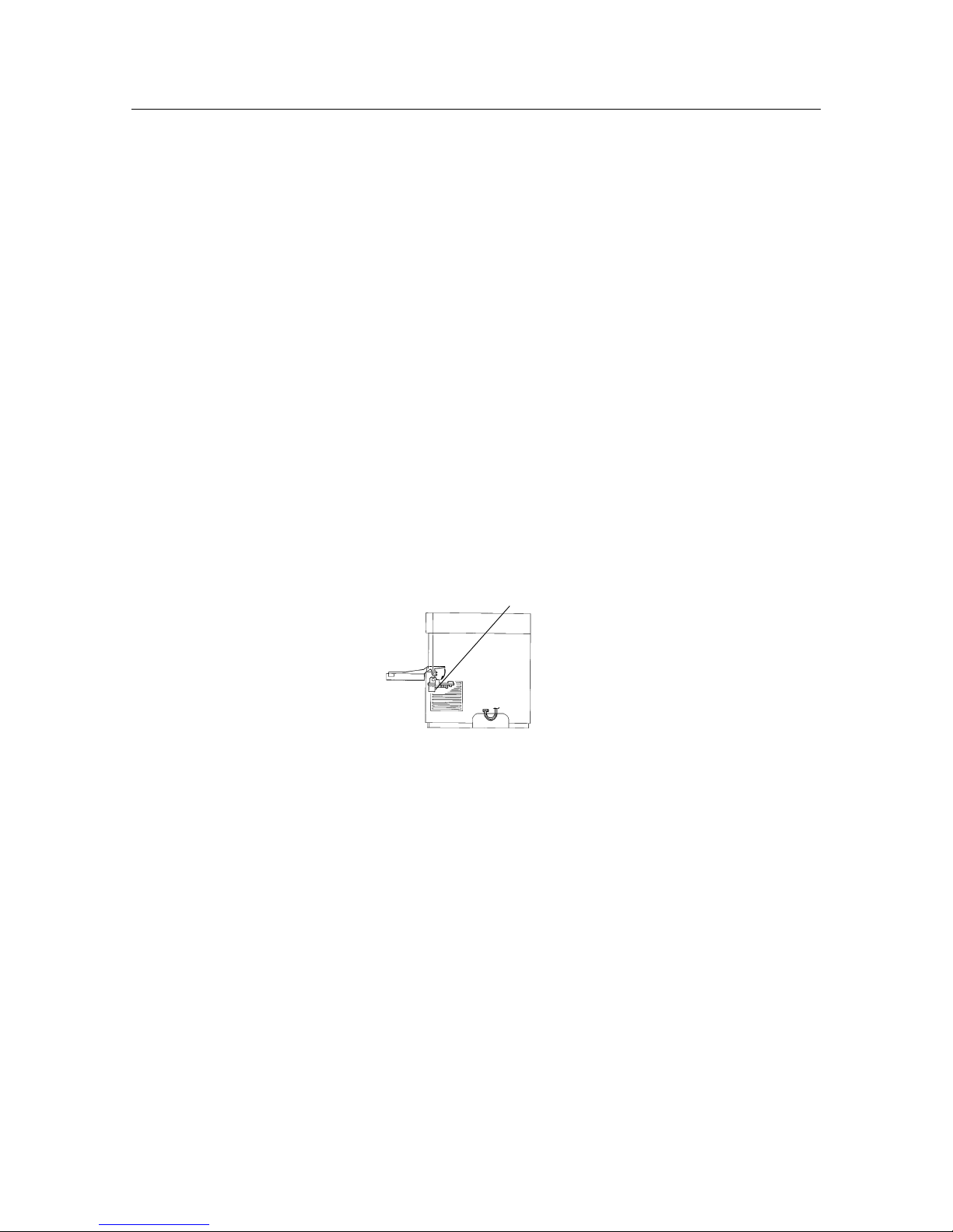
DANGER: In order to prevent exposure to the laser beam contained in the printer, the following precautions must
always be strictly observed.
Exposure to the laser beam can result in blindness.
• Never open a cover (ROS assembly) that has the label shown in figure 1-3 on it.
• When disassembling and adjusting the equipment, always make sure the power supply has been
turned off first.
• This equipment is provided with a two-stage safety switch function, so that it can be operated even
with the covers removed, by pressing the interlock switch. When using this method of operation, never
short the other switch at the same time (the second switch is pressed when the actuator at the back of
the EP toner cartridge attachment section is pressed).
• When servicing the printer’s optical system, be careful not to place screwdrivers or other reflective
objects in the path of the laser beam.
Be sure to take off accessories, such as watches and rings, before working on the printer. A reflected
beam, though invisible, can permanently damage your eyes.
Because the laser beam is invisible, be especially careful when servicing the optical system.
Figure 1-1 Itnerlock switch location
Itnerlock switch
Page 11
– 7 –
GENERAL SPECIFICATIONS
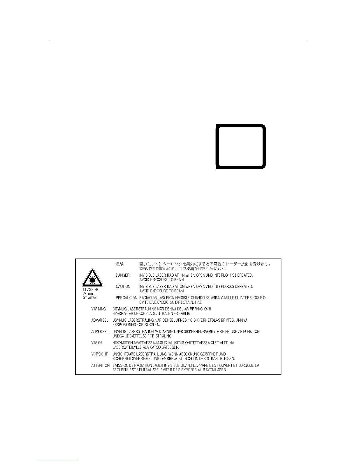
2-4. Laser safety
This printer is certified as a Class 1 laser product. This means that this laser product does not emit harmful laser beams.
This printer emits a Class 3B laser beam, but the beam is entirely enclosed within a protective case and an external cover,
and cannot escape from the printer while the printer is in use.
CLASS 1 LASER PRODUCT.
LUOKAN 1 LASERLAITE.
KLASS 1 LASER APPARAT.
CLASS 3B LASER
WAVE LENGTH 780nm (INVISIBLE)
RATED POWER 5mW
LUOKAN 3B LASER
AALLONPITUUS 780nm (NÄKYMÄTÖN)
TEHO 5mW
Figure 1-3 Caution Label
VARO! Avattaessa ja suojalukitus ohitettaessa olet alttiina näkymättömälle lasersäteilylle. Älä katso
säteeseen.
VARNING! Osynlig laserstrålning när denna del är öppnad och spärren är urkopplad. Betrakta ej strålen.
Laser Klasse 1
Laser de Classe 1
Láser Clase 1
Laser Luokan 1
Laser Klass 1
Figure 1-2 Class 1 Label
Page 12
– 8 –
GENERAL SPECIFICATIONS
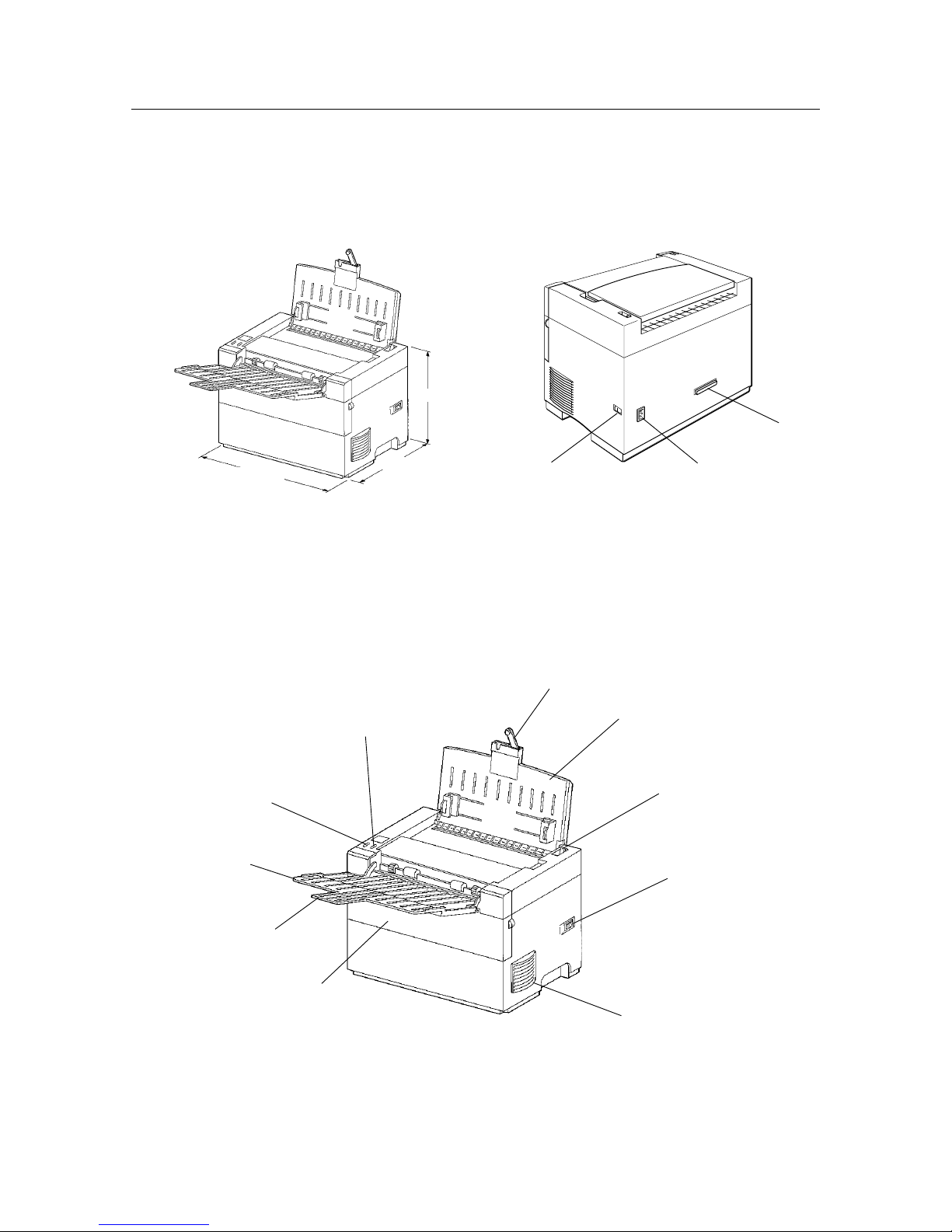
3. PRINTER COMPONENTS
Figure 1-4 External Dimensions Figure 1-5 Rear View
Figure 1-6 Front View
Power release lever
Power switch
Extension bar and
paper support extender
Upper paper tray
330 mm
235 mm
265 mm
Ventillation fan outlet
Front cover
Output paper
extender
Output tray
Ready LED lamp
(Green)
Error LED lamp
(Orange)
Power switch Power card socket
Parallel interface
connector
Page 13

2
CHAPTER 2
THEORY OF OPERATION
1. PRINTING PROCESS...........................................................................................11
2. PAPER TRANSPORTATION ...............................................................................14
3. FUNCTIONS OF THE MAIN PARTS....................................................................15
3.1 Covers.................................................................................................................... 15
3.2 Feeder & Drive ...................................................................................................... 15
3.3 Fuser & Paper Exit................................................................................................ 17
3.4 Photographics & ROS .......................................................................................... 19
3.5 Electrical................................................................................................................ 21
Page 14

– 10 –
THEORY OF OPERATION
Page 15
– 11 –
THEORY OF OPERATION
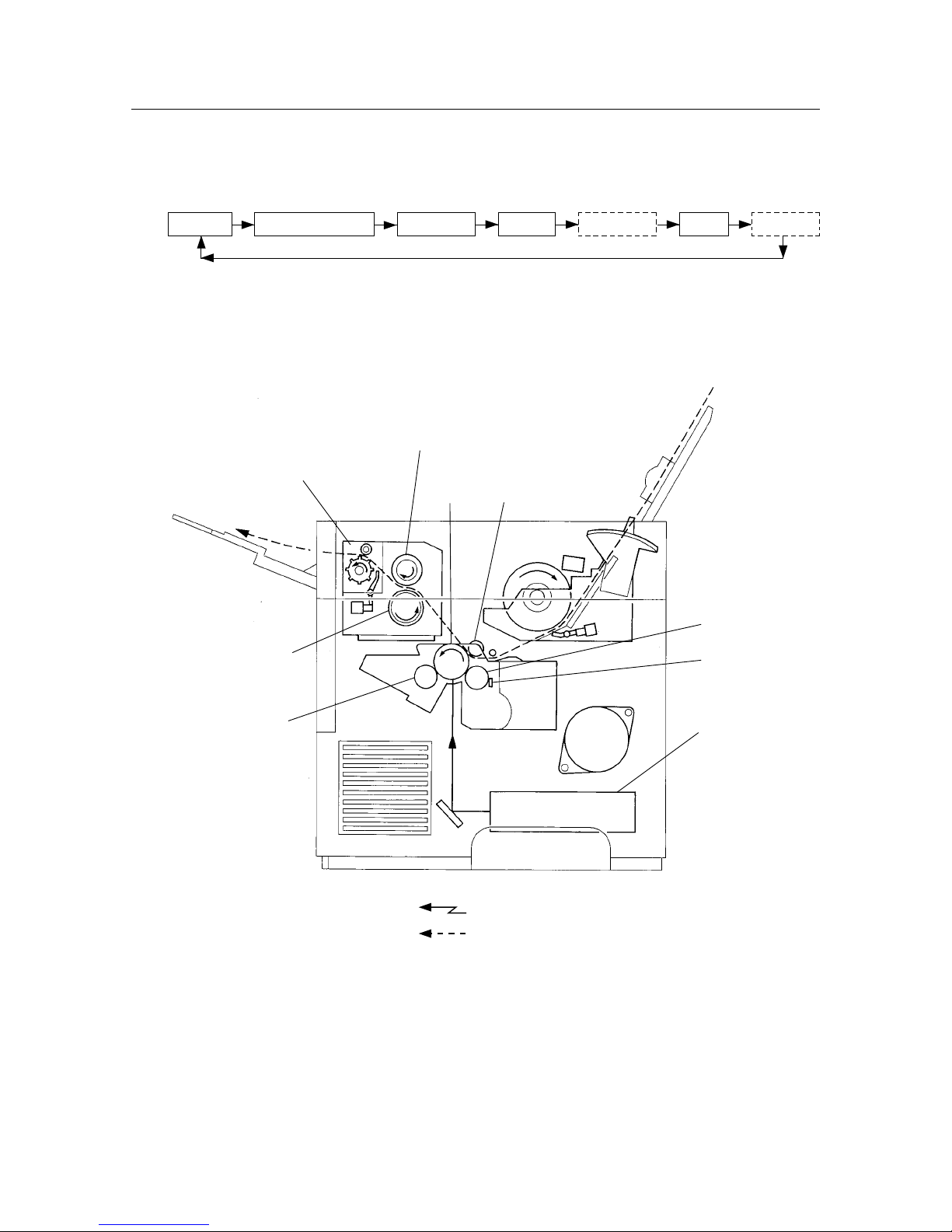
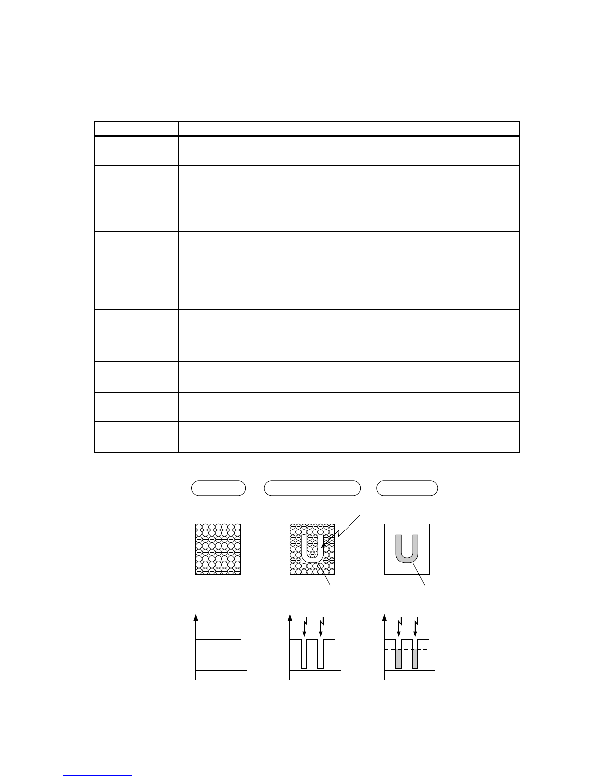
1. PRINTING PROCESS
The printing process for this system consists of the repetition of the following five basic steps:
Charging Scanning exposure Developing FusingTransfer
(Separation)
(Cleaning)
CM blade
Heat roller
Fuser assembly
Pressure roller
BTR
Drum
Magnetic roller
Ros assembly
BCR
Figure 2-1 Printing Process
: Laser beam
: Paper path
Page 16
– 12 –
THEORY OF OPERATION
• Description of the Printing Process
Step Details
Charging
The surface of the rotating drum in the EP toner cartridge is uniformly negatively charged
by the electric charge from the BCR (Bias Charge Roller).
The ROS assembly scans the exposure by converting the image signal from the MCU PWB
into an optical signal (laser beam) and directs the laser beam onto the drum.
Scanning Exposure When an image is present, a laser is emitted and the laser beam is irradiated onto the surface
of the drum causing the irradiated area to be set to a neutral charge, thus enabling an
invisible latent electrostatic image to be formed on the drum’s surface.
The latent electrostatic image on the drum’s surface attracts toner from the surface of the
magnetic roller in the EP toner cartridge, forming a visible image on the surface of the drum.
Developing
The magnet inside the magnetic roller causes the toner, which also has magnetic properties,
to adhere to the roller while the friction between the rotating magnetic roller and the CM
blade (Charge Metal Blade) negatively charges the toner, so that a thin layer of toner is n
the surface of the magnetic roller.
Transfer
A positive charge is applied to the back of the paper by the BTR (Bias Transfer Roller)
causing the toner on the drum’s surface to be transferred to the paper.
Applying a positive charge to the back of the paper causes the paper itself to be positively
charged, so that the paper adheres to the drum
(Separation)
The firmness of the paper causes the paper with the toner affixed to it to be separated from
the drum.
Fusing
The heat from the heat roller heated by the heat rod and the pressure from the pressure roller
causes the toner to be fused to the paper in the fuser assembly.
(Cleaning)
Any residual toner remaining on the drum after the transfer step is scraped off by the
cleaning blade which is in contact with the drum’s surface.
–350V
0
–V
–350V
0
–V
–350V
0
–V
–210V
(Developing bias)
Laser beam
Scanning Exposure DevelopingCharging
Toner image
(Visible image)
Electrostatic latent
image (Invisible image)
Drum’s surface
Voltage
Figure 2-2 Printing Process (Drum’s Surface)
Page 17

– 13 –
THEORY OF OPERATION
Cleaning blade
BCR
AC Bias: 1.6kVp-p
(f=2.4kHz)
DC Bias: –210V
Laser beam
Toner
DC Bias
(+): 250V~2600V
(0.5µA~1.6µA)
(–): –700V
Magnetic roll
AC Bias: 200µA
(f=160Hz)
DC Bias: –350V
Paper
Eliminator
Pressure roll
BTR
Drum
( 30mm)
CM blade
Toner
17.28
Heat roll
17
Transfer
Scanning Exposure
152˚C 140˚C
158˚C 150˚C
Separation
While the lamp
flashes
six times
After the lamp
flashes
the sixth time
Developing
Charging
Heat roll
Figure 2-3 Printing Process (Seven Steps)
Page 18
– 14 –
THEORY OF OPERATION
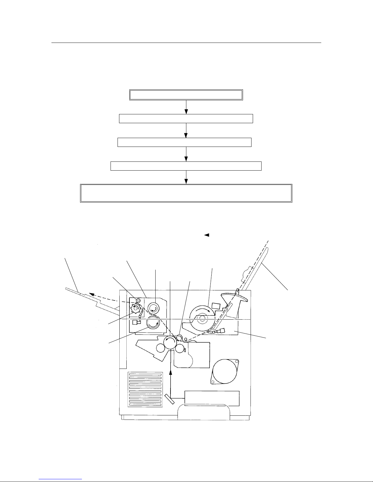
- - -
: Transport path of the paper
Input tray assembly
Feeder assembly
Heat roller
Pinch roller
Exit roller
Delivery tray assembly
Fuser assembly
Pressure roller
Drum
BTR
Feed roller
Figure 2-4 Paper Transportation
2. PAPER TRANSPORTATION
The following diagram shows the order in which paper passes over the rollers.
Paper that is inserted is automatically fed.
Paper is supplied and transported by the feed roller.
Paper is transported by the drum and BTR assembly.
Paper is transported by the heat roller and pressure roller.
Paper is discharged by the exit roller in the fuser assembly and the pinch roller in the
fuser top cover assembly.
Page 19

– 15 –
THEORY OF OPERATION
3. FUNCTIONS OF THE MAIN PARTS
The main parts are briefly described and illustrated as follows. In order to remain consistent with the parts list, parts are
divided into the following five sections based on their type.
1 Covers
2 Feeder & Drive
3 Fuser & Paper Exit
4 Photographics & ROS
5 Electrical
3.1 Covers
This consists of the printer, four covers and two trays.
(Refer to Chapter 6, Parts List)
3.2 Feeder & Drive
• Input Tray Assembly
Regular (cut sheet) paper, envelopes can be fed into the printer from this tray.
Slide the left and right paper guides to hold the paper in place.
• Feed Roller Assembly
This assembly consists of the feed roller and the feed clutch. After the spring clutch in the feed clutch has been set by
the movement of the feed solenoid, the feed roller assembly rotates driven by the drive assembly and the feed rollers
feed the paper into the printer from the input tray assembly.
One full rotation of the feed roller assembly causes the spring clutch to be released by the feed solenoid and disables
the drive assembly from transmitting a driving signal.
• Feed Solenoid
The feed solenoid controls the operations (rotation and stop) of the feed roller assembly.
• Pre-regi. Sensor
This sensor detects whether paper is sent by the paper set lever based on changes in the position of the regi. actuator
and sends a signal to the MCU PWB.
• MCU PWB
The MCU PWB controls the regi. solenoid, rotates the feed roller assembly and feeds the paper into the printer with
the paper set lever. After receiving the signal from the regi. sensor, the MCU PWB instructs the EP toner cartridge to
generate the image.
(Refer to section 3.5 Electrical System. Illustrations of the parts described above are shown in Chapter 6, Parts List
PL5.)
• Drive Assembly
The drive assembly consists of the main motor and the gear that transmits the driving force. This assembly transmits
a driving force by rotating the main motor.
Page 20
– 16 –
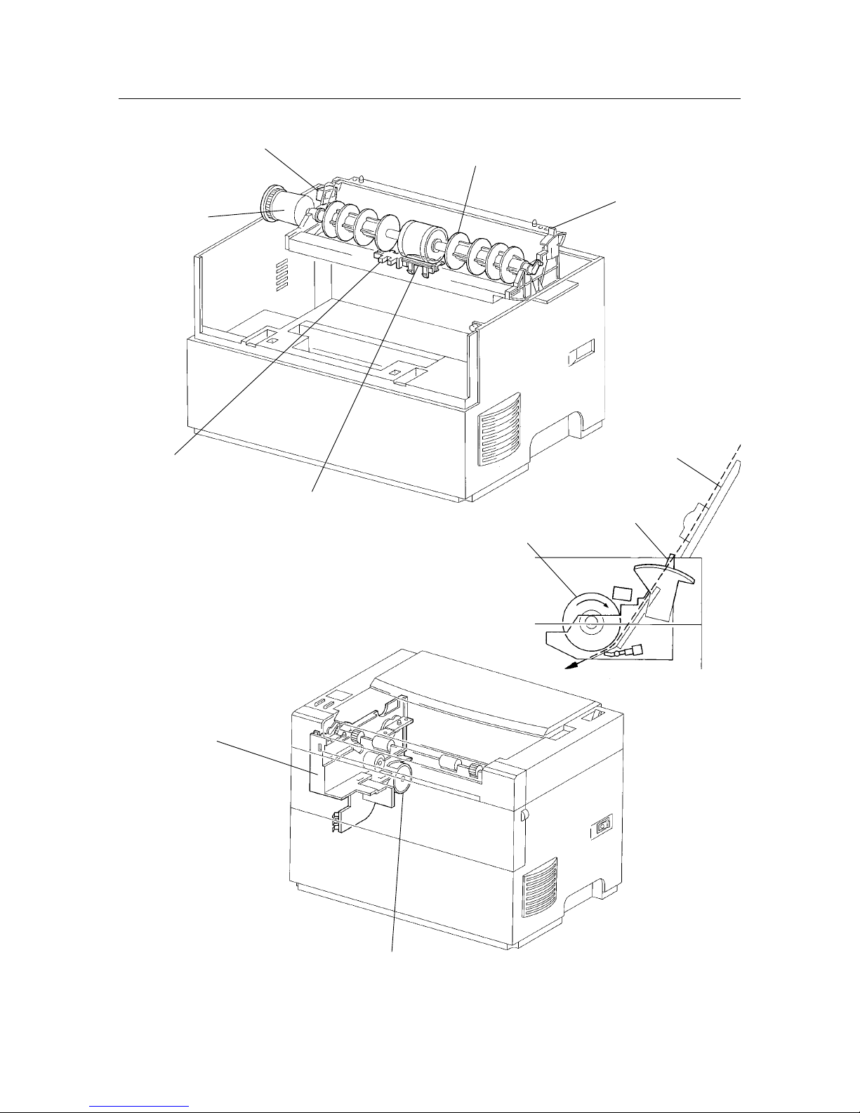
THEORY OF OPERATION
Feed clutch
Feed solenoid
Feed roller assembly
Paper set lever
Retard pad
Pre-regi. sensor
Figure 2-5 Feeder & Drive
Drive assembly
Main motor
Paper set lever
Input tray assembly
Feed roller
Page 21

– 17 –
THEORY OF OPERATION
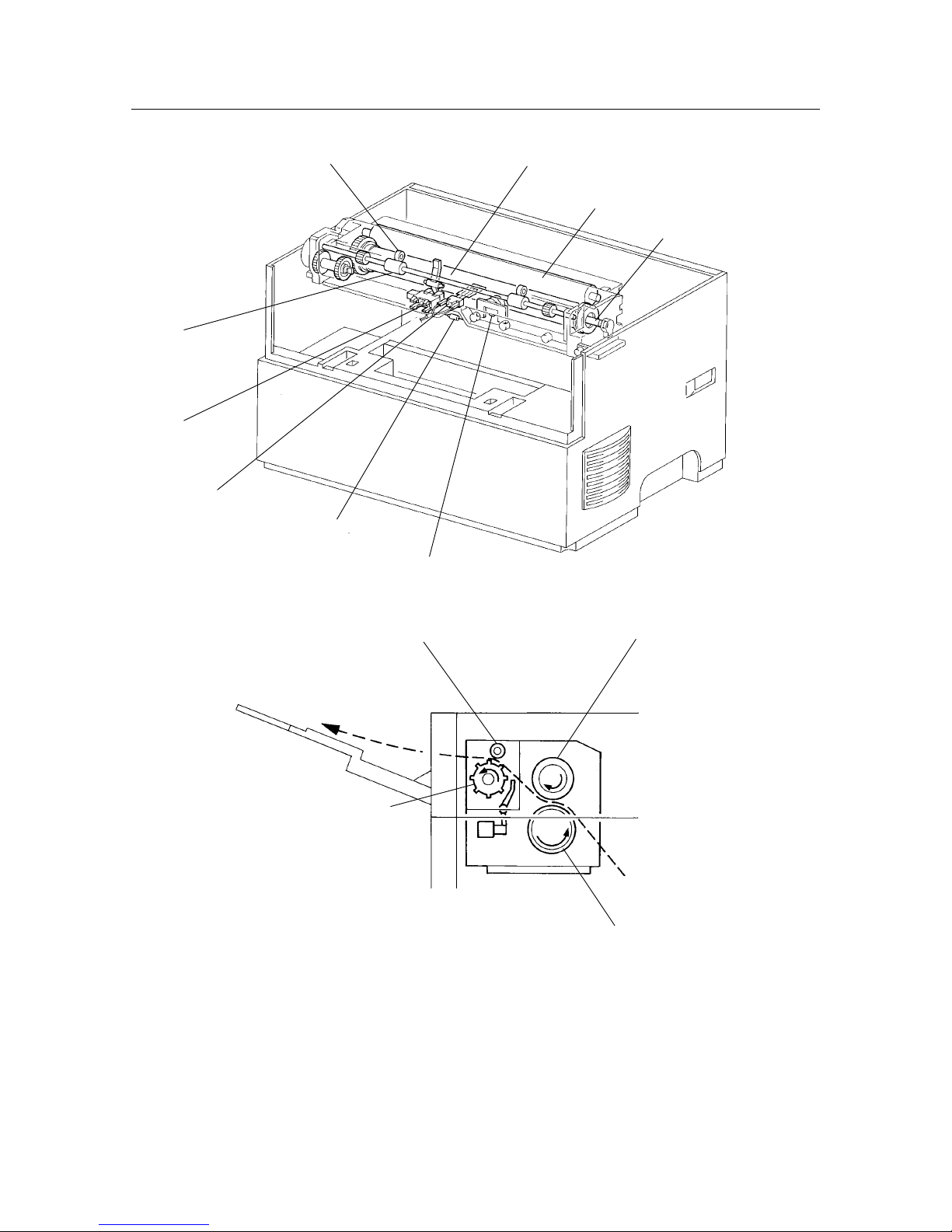
3.3 Fuser & Paper Exit
• Fuser Assembly
The fuser assembly includes the heater rod, heat roller, pressure roller, thermostat, thermistor and exit sensor. This
assembly fixes the toner onto the paper using heat and pressure, then outputs the printed paper.
Parts in the fuser assembly are referred to as fusers.
Heater Rod
The heater rod is a lamp with a heated coil sealed inside it and serves as the heat source inside the heat roller.
Heat Roller
The hollow, metal heat roller is coated on the surface and provides the heat to fuse the toner to the paper.
Pressure Roller
The rubber pressure roller provides the pressure to fuse the toner to the paper.
Thermistor
The thermistor is in contact with the heat roller and responds to its surface temperature.
When the heater rod is ON (a light is on), the thermistor controls the ON/OFF position of the heater rod according
to the temperature detected and prevents excessive increases in the primary temperature.
Thermostat
The thermostat is in series with the power supply in the heater rod. If the thermistor fails to prevent an excessive
increase in the (primary) temperature, the thermostat prevents an excessive increase in the secondary temperature
by opening the point of contact that results when the ambient temperature reaches a set level.
Thermal Fuse
The thermal fuse is in series with the heater rod circuit. If the thermistor fails to prevent the (primary) temperature
from getting too high and the thermostat fails to prevent the (secondary) temperature from getting too high, the
fuse will prevent tertiary overheating by melting when the ambient temperature reaches a set level.
Exit Roller
After fusing the toner onto the paper, the exit roller passes the printed paper out of the printer.
Exit Sensor
The exit sensor detects the state of the printed paper in the exit area in response to changes in the position of the
exit actuator. The exit sensor is turned ON when the presence of the printed paper is detected.
Page 22
– 18 –
THEORY OF OPERATION
Heat roller
Thermostat
Thermal fuse
Thermister
Exit sensor
Exit roller
Pressure roller
Heater rod
Pinch roller
Pinch roller
Pressure roller
Heat roller
Exit roller
Figure 2-6 Fuser & Paper Exit
Page 23

– 19 –
THEORY OF OPERATION
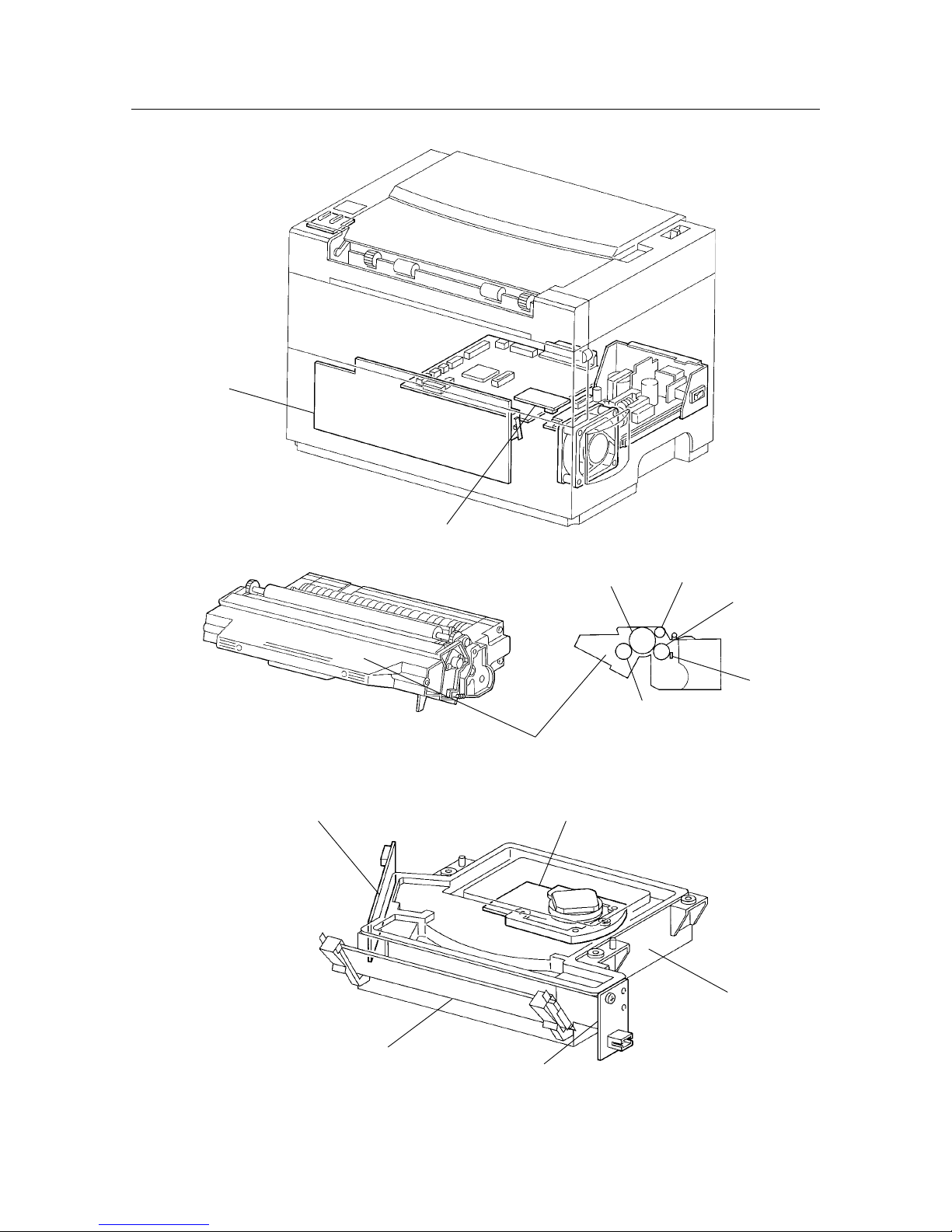
3.4 Photographics & ROS
• HVPS (HVPS: High Voltage Power Supply)
The HVPS supplies voltage/current to the BCR, magnetic roller, BTR and drum during the charging, developing and
transfer steps. It also supplies current to the fan. (The front cover interlock switch is mounted onto the HVPS.)
• ROS Assembly (ROS: Raster Output Scanner)
The ROS assembly consists of the LD assembly, the scanner assembly, the SOS PWB and the mirror. Parts in the ROS
assembly are referred to as ROS items.
LD Assembly (LD: Laser Diode)
The LD assembly converts electrical signals into a laser beam and emits light.
The laser diode output (LD power) is kept constant and transmitted through the monitor’s circuits.
Scanner Assembly
A polygonal mirror with four specular surfaces is mounted on the scanner motor which rotates at a constant speed.
The rotation of the polygonal mirror changes the laser beam’s angle of reflection and causes one surface of the
mirror to scan one line (in the direction of the drum’s axis).
The laser beam reflected by the polygonal mirror is irradiated onto the drum’s surface via the lens and mirror.
SOS PWB (SOS: Start of Scan)
The irradiation of the laser beam onto the SOS sensor causes the laser beam to be converted into an electrical signal
(SOS signal) and allows the initial scanning position of a line to be detected.
• CRU Sensor PWB (CRU: Customer Replaceable Unit)
The CRU sensor consists of a CRU switch which detects the presence of the EP toner cartridge and is turned ON or
OFF in response to the CRU actuator. The CRU switch is in series with the circuit emitting the laser beam and ensures
the safety of the laser beam.
• EP toner cartridge (EP: Electrical Photographics)
The EP toner cartridge consists of the drum, BCR, magnetic roller, CM blade and cleaning blade.
Drum
The drum is constructed of an aluminum cylinder covered with an OPC (organic photo conductor) sensitive material with
photoconductive properties (the ability to retain the electric charge in darkness and set the charge to neutral in light). The drum
produces a printed image based on the potential difference (latent electrostatic image) on its surface.
BCR (BCR: Bias Charge Roller)
The BCR sets the drum’s surface to a uniform electrical charge.
Magnetic Roller
The magnetic roller supplies toner to the drum for developing a latent electrostatic image on the surface of the drum.
BTR (BTR: Bias Transfer Roller)
The BTR applies a positive charge to the back of the paper and transfers the toner from the drum’s surface to the paper.
CM Blade (CM: Charge Metal)
The CM blade not only uniformly controls the amount of toner on the surface of the magnetic roller, but also uses friction to
give the toner its electric charge.
Cleaning Blade
The cleaning blade cleans the surface of the drum by scratching off the residual toner after the transfer step.
Page 24
– 20 –
THEORY OF OPERATION
Mirror
Scanner assemblyLD assembly
ROS assembly
SOS PWB
Magnetic roller
BTR
Drum
BCR
CM blade
EP toner cartridge
HVPS
CRU sensor
Figure 2-7 Photographics & Ros
Page 25
– 21 –
THEORY OF OPERATION
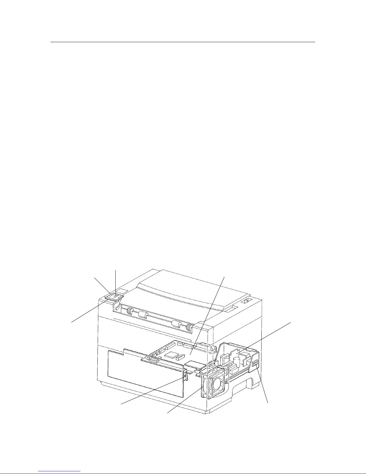
3.5 Electrical
• LED & LED PWB
The condition of the printer is displayed by LEDs (green/orange) and can be confirmed by observing these LEDs.
• LVPS Assembly (LVPS: Low Voltage Power Supply)
The LVPS assembly not only supplies AC power from the power supply to the heater rod in the fuser assembly, but
also generates and supplies a stable low-voltage DC power for use in the logic circuitry, etc.
It includes a main power switch which is used to turn the main power supply to the printer ON or OFF.
• MCU PWB
The MCU PWB controls the whole printing operation.
Its main functions are as follows:
(1) Receive information from the sensors and switches
(2) Control the ROS, fuser and drive assemblies
(3) Control the printing sequence
(4) Distribute low-voltage DC power from the LVPS assembly to each component
• Front Cover Interlock Switch
The interlock switch is a safety switch which completes or breaks the AC power circuit and the low-voltage (24V) DC
power circuit (but not the power supply to the fan) when the front cover assembly is closed or opened (the switch is
pressed or released). (This switch is mounted onto the HVPS.)
• Fan
The fan receives power from the HVPS and draws in air which is used to lower the internal temperature of the system,
thereby preventing it from increasing.
(Refer to section 1.2 Parts List in chapter 6, Parts List.)
Figure 2-8 Electrical
LVPS assembly
Main power switch
Front cover Interlock switch
LED PCW
MCU PWB
LED (orange)
LED (green)
Fan
Page 26
– 22 –
THEORY OF OPERATION
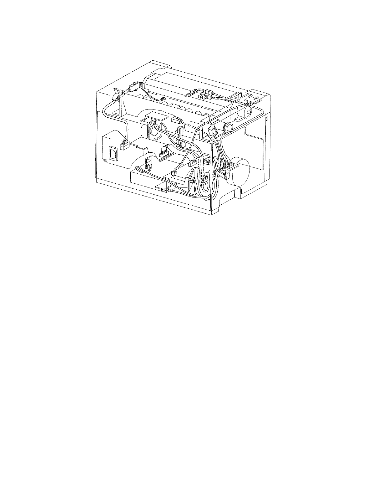
Figure 2-9 Electrical
Page 27

CHAPTER 3
REPLACEMENT AND ADJUSTMENTS OF PARTS
This chapter explains adjustment, disassembly and reassembly of the printer. The following precautions should be
noted during disassembly and reassembly:
1. Disconnect the printer from the wall outlet before servicing it.
2. Unless otherwise specified, the printer is assembled by reversing the disassembly procedure.
3. Do not operate the printer with any parts removed.
4. When you remove the EPX toner cartridge, be sure to keep the cartridge in its original box. If the box is not
available, cover the cartridge with a cloth or put it in a dark place to prevent light from affecting the drum inside
the cartridge.
3
1. COVERS ..............................................25
1.1 Front Cover .................................... 25
1.2 Top Cover ....................................... 26
1.3 Rear Cover...................................... 27
1.4 Bottom Cover ................................. 28
1.5 Fan .................................................. 29
2. FEEDER & DRIVE ...............................30
2.1 Feeder Assembly ........................... 30
2.2 Feed Roller Assembly ................... 31
2.3 Feed Solenoid ................................ 32
2.4 Paper Set Lever.............................. 33
2.5 Retard Pad...................................... 34
2.6 Pre-Regi. Sensor............................ 35
2.7 Drive Assembly.............................. 36
2.8 Main Motor...................................... 37
3. FUSER .................................................38
3.1 Fuser Assembly ............................. 38
3.2 Pressure Roller .............................. 39
3.3 Heater Rod...................................... 40
3.4 Heat Roller...................................... 42
3.5 Thermostat ..................................... 43
3.6 Thermal Fuse ................................. 44
3.7 Thermistor ...................................... 45
3.8 Exit Sensor ..................................... 46
4. ROS......................................................47
4.1 ROS Assembly ............................... 47
4.2 SOS Sensor Assembly .................. 48
4.3 Laser Diode .................................... 49
4.4 Scanner Assembly......................... 50
4.5 Mirror .............................................. 51
4.6 HVPS ............................................... 52
4.7 Front Cover Interlock Switch
Actuator .......................................... 53
4.8 CRU Sensor PWB & Actuator ....... 54
5. ELECTRICAL SYSTEM....................... 55
5.1 PWB Chassis.................................. 55
5.2 MCU PWB ....................................... 56
5.3 LVPS Assembly ............................. 57
Page 28

– 24 –
REPLACEMENT AND ADJUSTMENT OF PARTS
Page 29
– 25 –
REPLACEMENT AND ADJUSTMENT OF PARTS
Be sure that the power is disconnected!
1. COVERS
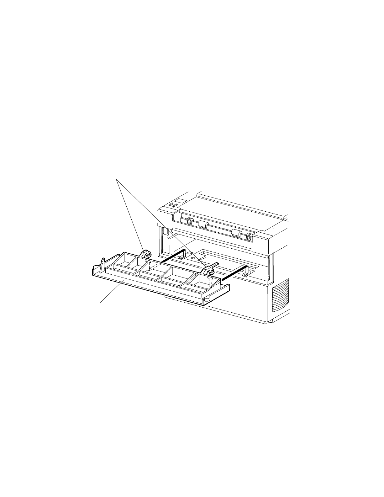
1.1 Front Cover
[Disassembly]
Warning: Turn off the power switch and disconnect the power supply cord from the wall outlet.
(1) Grasping the left and right sides of the front cover [1], open it by pulling it down.
(2) Remove the EP toner cartridge and keep it in a safe place.
(3) Pressing down on the center of the printer with one hand, separately unhook the left and right hinges
[2] on the front cover [1] and remove the front cover.
[Assembly]
Reverse the disassembly procedure.
[1]
[2]
Page 30
– 26 –
REPLACEMENT AND ADJUSTMENT OF PARTS
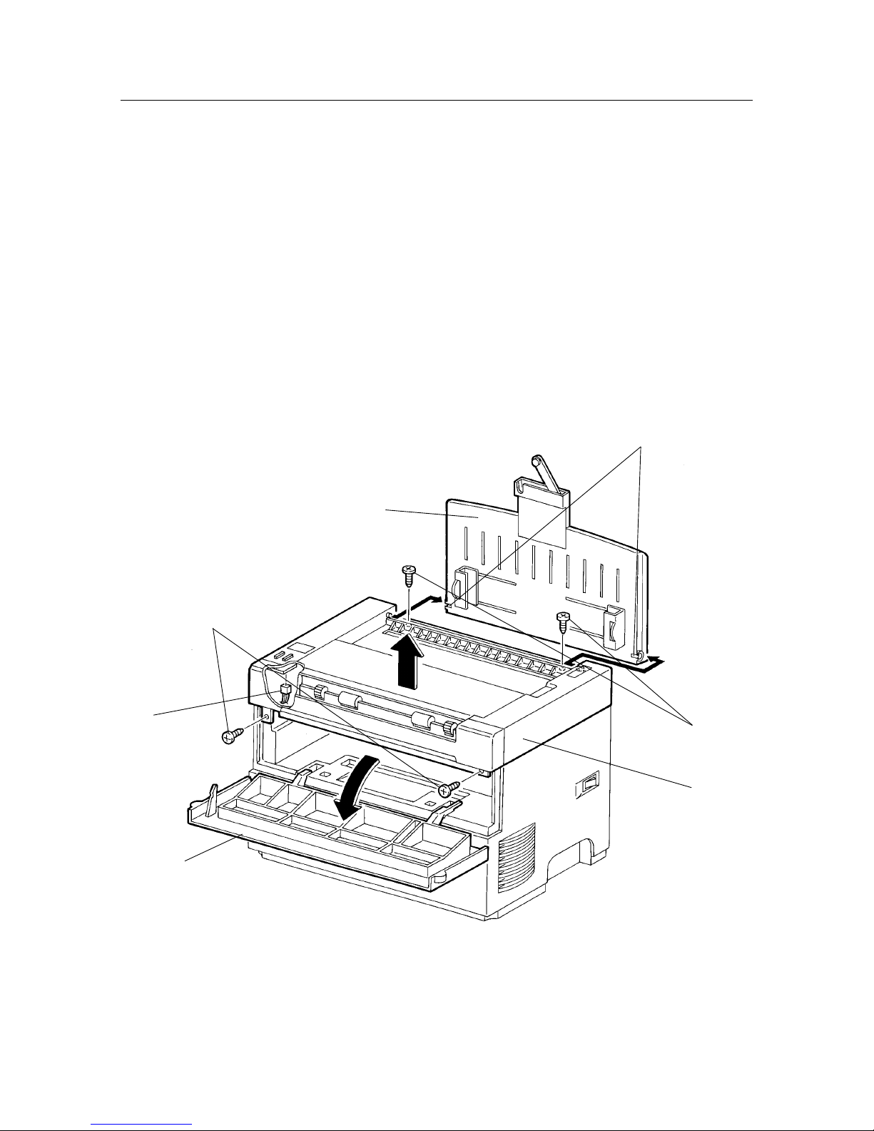
1.2 Top Cover
[Disassembly]
Warning: Turn off the power switch and disconnect the power supply cord from the wall outlet.
(1) Open the front cover [1], remove the EP toner cartridge and keep it in a safe place.
(2) Remove the two screws [2] that can be seen when the front cover is opened.
(3) While pressing down on the center of the printer with one hand, separately unhook the left and right
bosses [3] on the input tray assembly [4] and remove the input tray assembly.
Caution: In order to illustrate the positions of the screws in relation to the input tray assembly, fig.
(4) Remove the two screws [5] revealed when the input tray assembly is removed and raise the top cover
[6] a few centimeters.
(5) Raise the top cover to disconnect PJ321 [7] from the LED PWB.
[Assembly]
Reverse the disassembly procedure.
Caution: When installing the top cover [1] on the printer, be sure that the harness is not pinched between any other
parts.
[1]
[2]
[5]
[6]
[3]
[4]
[7]
Page 31

– 27 –
REPLACEMENT AND ADJUSTMENT OF PARTS
Be sure that the power is disconnected!
1.3 Rear Cover
[Disassembly]
Warning: Turn off the power switch and disconnect the power supply cord from the wall outlet.
Remove the EP toner cartridge and keep it in a safe place.
(1) Disconnect the printer’s power cord from the wall outlet.
(2) Remove the two screws [1] securing the MCU PWB interface connector (PJ31) to the rear cover.
(3) Remove the two screws [2] on the top left and right that are attaching the rear cover to the printer.
(4) Remove the center screw and the two screws [3] on the bottom left and right and remove the rear cover
[4].
[Assembly]
Reverse the disassembly procedure.
[3]
[4]
[2] [1]
Page 32

– 28 –
REPLACEMENT AND ADJUSTMENT OF PARTS
1.4 Bottom Cover
[Disassembly]
Warning: Turn off the power switch and disconnect the power supply cord from the wall outlet.
Remove the EP toner cartridge and keep it in a safe place.
(1) Remove the front cover. (Refer to section 1.1)
Caution: Be careful not to break the front cover interlock actuator when installing the bottom cover while the front
cover is removed.
(2) Turn the printer over onto its top cover. (Turn it upside down.)
(3) Remove the four screws [1] securing the bottom cover and remove the bottom cover [2].
(4) Disconnect CN121 [3] from the laser diode [4] and remove the harness [5] from the bottom cover.
(5) Disconnect PJ152 [6] from the HVPS and remove the bottom cover.
[Assembly]
Reverse the disassembly procedure.
Caution 1: Pass the harness [5] through the bottom cover [2], then connect it to connector CN 121. Do not connect the
harness directly to connector CN 121 [3] without passing it through the bottom cover.
Caution 2: Insert PJ152 from the fan into the HVPS before installing the bottom cover.
[2]
[5]
[6]
[1]
[4]
[3]
Page 33

– 29 –
REPLACEMENT AND ADJUSTMENT OF PARTS
Be sure that the power is disconnected!
1.5 Fan
[Disassembly]
Warning: Turn off the power switch and disconnect the power supply cord from the wall outlet.
Remove the EP toner cartridge and keep it in a safe place.
(1) Remove the bottom cover. (Refer to section 1.4)
(2) Disconnect PJ152 [1] attaching the HVPS to the fan [2].
(3) Inserting a miniature standard screwdriver [3] between the bottom cover [4] and fan [2], unhook the
latch and remove the fan.
[Assembly]
Reverse the disassembly procedure.
[4]
[3]
[2]
[1]
Page 34

– 30 –
REPLACEMENT AND ADJUSTMENT OF PARTS
2. FEEDER & DRIVE
2.1 Feeder Assembly
[Disassembly]
Warning: Turn off the power switch and disconnect the power supply cord from the wall outlet.
Remove the EP toner cartridge and keep it in a safe place.
(1) Remove the top cover. (Refer to section 1.2)
(2) Remove the four screws [1] securing the feeder assembly [2].
(3) Disconnect PJ181 [3] from the pre-regi. sensor.
(4) Remove the rear cover. (Refer to section 1.3)
(5) Disconnect PJ16 [4] from the MUC PWB and remove the feeder assembly [2].
[Assembly]
Reverse the disassembly procedure.
Caution: When installing the feeder assembly [2] on the printer, be sure the harnesses [6] are not pinched between
any other parts.
[2]
[6]
[4]
[3]
[1]
[1]
Page 35

– 31 –
REPLACEMENT AND ADJUSTMENT OF PARTS
Be sure that the power is disconnected!
2.2 Feed Roller Assembly
[Disassembly]
Warning: Turn off the power switch and disconnect the power supply cord from the wall outlet.
Remove the EP toner cartridge and keep it in a safe place.
(1) Remove the following units:
• Top cover (Refer to section 1.2)
• Feeder assembly (Refer to section 2.1)
• Spring [1].
• Feed roller assembly [2]
Pressing down on the feeder frame [3] of the feeder assembly, separately unhook the left and right
ends of the feed roller assembly [2] and remove it.
[Assembly]
Reverse the disassembly procedure.
[2]
[1]
[3]
Page 36

– 32 –
REPLACEMENT AND ADJUSTMENT OF PARTS
2.3 Feed Solenoid
[Disassembly]
Warning: Turn off the power switch and disconnect the power supply cord from the wall outlet.
Remove the EP toner cartridge and keep it in a safe place.
(1) Remove the following units:
• Top cover (Refer to section 1.2)
• Feeder assembly (Refer to section 2.1)
• Screw [1]
• Feeder solenoid [2]
• Feed roller assembly [3]
[Assembly]
Reverse the disassembly procedure.
Caution: When installing the feed solenoid [2] on the feeder assembly, align the hole in the stabilizing boss [4] on
the feeder frame [5] with the hole on the feed solenoid. Tighten the screw while pressing down on the back
of the feed solenoid.
[2]
[1]
[5]
[4]
[3]
Page 37

– 33 –
REPLACEMENT AND ADJUSTMENT OF PARTS
Be sure that the power is disconnected!
2.4 Paper Set Lever
[Disassembly]
Warning: Turn off the power switch and disconnect the power supply cord from the wall outlet.
Remove the EP toner cartridge and keep it in a safe place.
(1) Remove the following units:
• Top cover (Refer to section 1.2)
• Feeder assembly (Refer to section 2.1)
• Spring [1]
• Paper set lever [2]
[Assembly]
Reverse the disassembly procedure.
[1]
[2]
Page 38

– 34 –
REPLACEMENT AND ADJUSTMENT OF PARTS
2.5 Retard Pad
[Disassembly]
Warning: Turn off the power switch and disconnect the power supply cord from the wall outlet.
Remove the EP toner cartridge and keep it in a safe place.
(1) Remove the following units:
• Top cover (Refer to section 1.2)
• Feed roller assembly (Refer to section 2.2)
• Retard pad [1]
Press together the retard pad clips [2] on the back of the feeder frame [3] and remove the retard pad.
Caution: When removing the retard pad [1], do not to lose the spring [4] that is installed behind it.
[Assembly]
Reverse the disassembly procedure.
[2]
[4]
[3]
[1]
Page 39

– 35 –
REPLACEMENT AND ADJUSTMENT OF PARTS
Be sure that the power is disconnected!
2.6 Pre-Regi. Sensor
[Disassembly]
Warning: Turn off the power switch and disconnect the power supply cord from the wall outlet.
Remove the EP toner cartridge and keep it in a safe place.
(1) Remove the following units:
• Top cover (Refer to section 1.2)
• Feeder assembly (Refer to section 2.1)
• Pre-regi. sensor [1]
Unhook the pre-regi. sensor clips [2] on the back of the feeder frame and remove the pre-regi.
sensor [1].
[Assembly]
Reverse the disassembly procedure.
[2]
[1]
Page 40

– 36 –
REPLACEMENT AND ADJUSTMENT OF PARTS
2.7 Drive Assembly
[Disassembly]
Warning: Turn off the power switch and disconnect the power supply cord from the wall outlet.
Remove the EP toner cartridge and keep it in a safe place.
(1) Remove the following units:
• Feeder assembly (Refer to section 2.1)
• Fuser assembly (Refer to section 3.1)
• Rear cover (Refer to section 1.3)
• PJ14 [1]
Remove the three screws [2] securing the drive assembly and, while lifting the rear of the drive
assembly [3], remove it.
[Assembly]
Reverse the disassembly procedure.
Caution: Remove the bottom cover (refer to section 1.4) and be sure the HVPS terminal [4] on the drive assembly
[3] is securely connected to the HVPS.
[4]
[1]
[3]
[2]
Page 41

– 37 –
REPLACEMENT AND ADJUSTMENT OF PARTS
Be sure that the power is disconnected!
2.8 Main Motor
[Disassembly]
Warning: Turn off the power switch and disconnect the power supply cord from the wall outlet.
Remove the EP toner cartridge and keep it in a safe place.
(1) Remove the following units:
• Top cover assembly (Refer to section 1.2)
• Feeder assembly (Refer to section 2.1)
• Fuser assembly (Refer to section 3.1)
• Drive assembly (Refer to section 2.7)
• Two screws [1]
• Main motor [2]
[Assembly]
Reverse the disassembly procedure.
Note: Since the holes [3] attaching the main motor [2] to the drive assembly determine the position in which it is
installed, it is not necessary to adjust the backlash.
Caution: Install the main motor with the harness [4] facing towards the rear.
[2]
[4]
[3]
[1]
Page 42

– 38 –
REPLACEMENT AND ADJUSTMENT OF PARTS
3. FUSER
3.1 Fuser Assembly
[Disassembly]
Warning: Turn off the power switch and disconnect the power supply cord from the wall outlet.
Remove the EP toner cartridge and keep it in a safe place.
Caution: Be very careful not to get burnt when working on the fuser since it becomes hot while the printer is being
operated.
(1) Remove the following units:
• Top cover (Refer to section 1.2)
• PJ114 [1]
• PJ131 [2]
• PJ132 [3]
• Screws [4]
• Fuser assembly [5]
Remove the two screws [4] securing the fuser and while lifting the rear of the fuser assembly [5],
remove it from the frame.
[Assembly]
Reverse the disassembly procedure.
Caution: When installing the fuser assembly [5] on the printer, be sure the harnesses are not pinched between any other
parts.
[1]
[4]
[5]
[2]
[3]
Page 43

– 39 –
REPLACEMENT AND ADJUSTMENT OF PARTS
Be sure that the power is disconnected!
3.2 Pressure Roller
[Disassembly]
Warning: Turn off the power switch and disconnect the power supply cord from the wall outlet.
Remove the EP toner cartridge and keep it in a safe place.
Caution: Be careful not to get burnt when working on the fuser since it becomes very hot while the printer is being
operated.
(1) Remove the following units:
• Fuser assembly (Refer to section 3.1)
• Screw [1]
• Two screws [2]
• Fuser cover [3]
Lift the fuser cover from the fuser assembly [4].
• Pressure roller [5]
Turn over the fuser cover [3], remove the two screws [6] securing the inlet chute and remove
the pressure roller [5].
[Assembly]
Reverse the disassembly procedure.
Caution 1: When installing PJ114, be sure the green ground wire [7] and the diodes are installed correctly. (The diodes
should be installed with the cathode marks in the correct position.)
Caution 2: The ground plate on the inlet chute [8] should be in contact with the pressure roller shaft [5] (silver-colored
section).
[6]
[5]
[3]
[4]
[2]
[3]
[1]
[7]
[2]
[8]
Cathode marks
Page 44

– 40 –
REPLACEMENT AND ADJUSTMENT OF PARTS
3.3 Heater Rod
[Disassembly]
Warning: Turn off the power switch and disconnect the power supply cord from the wall outlet.
Remove the EP toner cartridge and keep it in a safe place.
Caution 1: Be careful not to get burnt when working on the fuser since it becomes very hot while the printer is being
operated.
(1) Remove the following units:
• Fuser assembly (Refer to section 3.1)
• Screw [1]
• Two screws [2]
• Fuser cover [3]
• Two screws [4]
• Fuser right housing [5]
• Screw [6]
• Two screws [7]
• Fuser left housing [8]
• Pinch roller [9]
[4]
[6]
[2]
[3]
[5]
[9]
[1]
[2]
[7]
[8]
Page 45

– 41 –
REPLACEMENT AND ADJUSTMENT OF PARTS
Be sure that the power is disconnected!
(2) Remove the following units:
• Two screws [10]
• Paper guide [11]
Caution 2: Do not to lose the spring [12] that is placed over the screws.
• Screw [13]
(3) Pull out the heater rod [14] from the heat roller [15].
Caution 3: Do not touch the glass surface of the heater rod [14] since oil from your hands may damage
it.
[Assembly]
Reverse the disassembly procedure.
Caution: When installing PJ114 [17], be sure the green ground wire [16] and the diodes are installed correctly. (The
diodes should be installed with the cathode marks in the correct position.)
[10]
[10]
[12]
[12]
[11]
[14]
[15]
[13]
[16]
[17]
Page 46

– 42 –
REPLACEMENT AND ADJUSTMENT OF PARTS
3.4 Heat Roller
[Disassembly]
Warning: Turn off the power switch and disconnect the power supply cord from the wall outlet.
Remove the EP toner cartridge and keep it in a safe place.
Caution: Be careful not to get burnt when working on the fuser since it becomes very hot while the printer is being
operated.
(1) Remove the following units:
• Fuser assembly (Refer to section 3.1)
• Pressure roller (Refer to section 3.2)
• Heater rod (Refer to section 3.3)
• Heat roller [1] (Refer to section 3.3)
Sliding the right and left ends of the H/R bearing [2] in the direction of the arrow, remove the heat
roller [1].
[Assembly]
Reverse the disassembly procedure.
Caution: There is only one correct way to install the gear [3]. Insert the tab [4] on the gear into the notch [5] on the
heat roller. (Do not install the gear in any other manner.)
[3]
[5]
[2]
[2]
[1]
[1]
[2]
[4]
Page 47

– 43 –
REPLACEMENT AND ADJUSTMENT OF PARTS
Be sure that the power is disconnected!
3.5 Thermostat
[Disassembly]
Warning: Turn off the power switch and disconnect the power supply cord from the wall outlet.
Remove the EP toner cartridge and keep it in a safe place.
Caution: Be careful not to get burnt when working on the fuser since it becomes very hot while the printer is being
operated.
(1) Remove the following units:
• Fuser (Refer to section 3.1)
• Pressure roller (Refer to section 3.2)
• Heater rod (Refer to section 3.3)
• Heat roller (Refer to section 3.4)
• Electrical frame [1]
Pull out the exit sensor actuator [2], remove the two screws [3] on the electrical frame used to attach
the thermostat and thermistor and detach it [1] from the fuser frame [4].
• Two screws [5]
• Thermostat [6]
[Assembly]
Reverse the disassembly procedure.
[1]
[5]
[6]
[2]
[3]
[4]
Page 48

– 44 –
REPLACEMENT AND ADJUSTMENT OF PARTS
3.6 Thermal Fuse
[Disassembly]
Warning: Turn off the power switch and disconnect the power supply cord from the wall outlet.
Remove the EP toner cartridge and keep it in a safe place.
Caution: Be careful not to get burnt when working on the fuser since it becomes very hot while the printer is being
operated.
(1) Remove the following units:
• Fuser (Refer to section 3.1)
• Pressure roller (Refer to section 3.2)
• Heater rod (Refer to section 3.3)
• Heat roller (Refer to section 3.4)
• Electrical frame [1]
Pull out the exit sensor actuator [2], remove the two screws [3] on the electrical frame used to attach
the thermostat and thermistor and detach it [1] from the fuser frame [4].
(2) Loosen the screw [5] securing the thermostat and the screw [6] securing the plate and remove the
thermal fuse [7].
[Assembly]
Reverse the disassembly procedure.
[4]
[7]
[6]
[5]
[2]
[3]
[1]
Page 49

– 45 –
REPLACEMENT AND ADJUSTMENT OF PARTS
Be sure that the power is disconnected!
3.7 Thermistor
[Disassembly]
Warning: Turn off the power switch and disconnect the power supply cord from the wall outlet.
Remove the EP toner cartridge and keep it in a safe place.
Caution: Be careful not to get burnt when working on the fuser since it becomes very hot while the printer is being
operated.
(1) Remove the following units:
• Fuser (Refer to section 3.1)
• Pressure roller (Refer to section 3.2)
• Heater rod (Refer to section 3.3)
• Heat roller (Refer to section 3.4)
• Electrical frame (Refer to section 3.5)
Pull out the exit sensor actuator, remove the two screws on the electrical frame used to attach the
thermostat and thermistor and detach it from the fuser frame.
• Screw [1]
• Thermistor [2]
[Assembly]
Reverse the disassembly procedure.
Caution: Install the thermistor [2] so that it is touching with the back of the heat roller.
[1]
[2]
Page 50

– 46 –
REPLACEMENT AND ADJUSTMENT OF PARTS
3.8 Exit Sensor
[Disassembly]
Warning: Turn off the power switch and disconnect the power supply cord from the wall outlet.
Remove the EP toner cartridge and keep it in a safe place.
Caution: Be careful not to get burnt when working on the fuser since it becomes very hot while the printer is being
operated.
(1) Remove the following units:
• Fuser (Refer to section 3.1)
• Pressure roller (Refer to section 3.2)
• Heater rod (Refer to section 3.3)
• Heat roller (Refer to section 3.4)
• Electrical frame (Refer to section 3.5)
Pull out the exit sensor actuator, remove the two screws on the electrical frame used to attach the
thermostat and thermistor and detach it from the fuser frame.
(2) Press together the exit sensor [1] clips [2] and remove it from the fuser frame [3].
[Assembly]
Reverse the disassembly procedure.
[3]
[2]
[3]
[1]
Page 51

– 47 –
REPLACEMENT AND ADJUSTMENT OF PARTS
Be sure that the power is disconnected!
4. ROS
4.1 ROS Assembly
[Disassembly]
Warning: Turn off the power switch and disconnect the power supply cord from the wall outlet.
Remove the EP toner cartridge and keep it in a safe place.
The ROS must not be running while it is being handled.
(1) Turn the printer over onto its top cover. (Turn it upside down.)
(2) Remove the bottom cover. (Refer to section 1.4)
(3) Disconnect CN122 [1] from the scanner assembly [2].
(4) Disconnect CN121 [3] from the laser diode [4].
(5) Disconnect CN123 [5] from the SOS sensor assembly [6].
(6) Remove the three screws [7] securing the ROS assembly and remove the ROS assembly [8].
[Assembly]
Reverse the disassembly procedure.
Caution: When installing the ROS assembly on the printer, align the holes in the stabilizing bosses and ROS assembly
before inserting the screws.
[8]
[2]
[7]
[4]
[3]
[6]
[5]
[1]
Page 52

– 48 –
REPLACEMENT AND ADJUSTMENT OF PARTS
4.2 SOS Sensor Assembly
[Disassembly]
Warning: Turn off the power switch and disconnect the power supply cord from the wall outlet.
Remove the EP toner cartridge and keep it in a safe place.
The ROS must not be running while it is being handled.
(1) Turn the printer over onto its top cover. (Turn it upside down.)
(2) Remove the following units:
• Bottom cover (Refer to section 1.4)
• ROS assembly (Refer to section 4.1)
• Screw [1]
• SOS sensor assembly [2]
[Assembly]
Reverse the disassembly procedure.
[2]
[1]
Page 53

– 49 –
REPLACEMENT AND ADJUSTMENT OF PARTS
Be sure that the power is disconnected!
4.3 Laser Diode
[Disassembly]
Warning: Turn off the power switch and disconnect the power supply cord from the wall outlet.
Remove the EP toner cartridge and keep it in a safe place.
The ROS must not be running while it is being handled.
(1) Turn the printer over onto its top cover. (Turn it upside down.)
(2) Remove the following units:
• Bottom cover (Refer to section 1.4)
• ROS assembly (Refer to section 4.1)
• Two screws [1]
• Laser diode [2]
Caution: The two (gold) screws covered with red paint must not be removed. If they are removed and the printer is
operated, the direction of the laser beam will change, affecting the picture quality considerably.
[Assembly]
Reverse the disassembly procedure.
[1]
[2]
Page 54

– 50 –
REPLACEMENT AND ADJUSTMENT OF PARTS
4.4 Scanner Assembly
[Disassembly]
Warning: Turn off the power switch and disconnect the power supply cord from the wall outlet.
Remove the EP toner cartridge and keep it in a safe place.
The ROS must not be running when it is being handled.
(1) Turn the printer over onto its top cover. (Turn it upside down.)
(2) Remove the bottom cover. (Refer to section 1.4)
(3) Disconnect CN122 [1] from the scanner assembly [2].
(4) Remove the three screws [3] securing the scanner assembly to the ROS assembly and remove the
scanner assembly [2].
Note: When removing the scanner assembly [2] only, it is not necessary to remove the ROS assembly [4] from the
printer as well.
[Assembly]
Reverse the disassembly procedure.
Caution: When installing the scanner assembly [2] onto the ROS assembly [4], align the holes in the stabilizing bosses
on the ROS assembly and scanner assembly before inserting the screws [3].
[2]
[1]
[4]
[3]
[5]
Page 55

– 51 –
REPLACEMENT AND ADJUSTMENT OF PARTS
Be sure that the power is disconnected!
4.5 Mirror
[Disassembly]
Warning: Turn off the power switch and disconnect the power supply cord from the wall outlet.
Remove the EP toner cartridge and keep it in a safe place.
The ROS must not be running while it is being handled.
(1) Turn the printer over onto its top cover. (Turn it upside down.)
(2) Remove the bottom cover. (Refer to section 1.4)
(3) Disconnect CN122 [1] from the scanner [2].
(4) Disconnect CN121 [3] from the laser diode [4].
(5) Disconnect CN123 [5] from the SOS sensor [6].
(6) Remove the three screws [7] securing the ROS assembly.
[Assembly]
Reverse the disassembly procedure.
Caution: Do not scratch or touch the front surface of the mirror with your hand; also, be sure to use the mirror clips
[9] to install it on the ROS assembly.
[2]
[1]
[4]
[3]
[6]
[5]
[7]
Page 56

– 52 –
REPLACEMENT AND ADJUSTMENT OF PARTS
4.6 HVPS
[Disassembly]
Warning: Turn off the power switch and disconnect the power supply cord from the wall outlet.
Remove the EP toner cartridge and keep it in a safe place.
(1) Remove the following units:
• Front cover (Refer to section 1.1)
• Bottom cover (Refer to section 1.4)
(2) Turn the printer onto its front. (Turn it sideways so that the front of the printer is pointing downwards.)
(3) Disconnect PJ151 [1] from the HVPS [2].
(4) Inserting a miniature standard screwdriver [3] into the small hinge hole [4] on the front cover, unhook
the latch supporting the HVPS and remove the HVPS [2].
Caution: If, while the HVPS is being removed, it catches on the drive assembly, carefully remove it without damaging
the contacts.
Note: The HVPS is supported by the latch mentioned above in (4) and the slot on the bottom cover.
[Assembly]
Reverse the disassembly procedure.
Caution: If, while the HVPS is being installed, it catches on the drive assembly, use a ruler or any other flat object
to guide in the HVPS without damaging any contacts.
[1]
[2]
[3]
[4]
Page 57

– 53 –
REPLACEMENT AND ADJUSTMENT OF PARTS
Be sure that the power is disconnected!
4.7 Front Cover Interlock Switch Actuator
[Disassembly]
Warning: Turn off the power switch and disconnect the power supply cord from the wall outlet.
Remove the EP toner cartridge and keep it in a safe place.
(1) Remove the bottom cover. (Refer to section 1.4)
(2) Turn the printer onto its front. (Turn it sideways so that the front of the printer is pointing downwards.)
(3) Remove the screw [1] securing the front cover interlock switch actuator [2] and remove the actuator.
[Assembly]
Reverse the disassembly procedure.
[1]
[2]
Page 58

– 54 –
REPLACEMENT AND ADJUSTMENT OF PARTS
4.8 CRU Sensor PWB & Actuator
[Disassembly]
Warning: Turn off the power switch and disconnect the power supply cord from the wall outlet.
Remove the EP toner cartridge and keep it in a safe place.
(1) Turn the printer onto its front. (Turn it sideways so that the front of the printer is pointing downwards.)
(2) Remove the following units:
• Bottom cover (Refer to section 1.4)
• Two screws [1]
• CRU sensor actuator cap [2]
• CRU sensor actuator [3]
• PJ171 [4]
• Two screws [5]
• CRU sensor PWB [6]
[Assembly]
Reverse the disassembly procedure.
[3]
[2]
[6]
[4]
[1]
[5]
Page 59

– 55 –
REPLACEMENT AND ADJUSTMENT OF PARTS
Be sure that the power is disconnected!
5. ELECTRICAL
5.1 PWB Chassis (including the MCU PWB and LVPS)
[Disassembly]
Warning: Turn off the power switch and disconnect the power supply cord from the wall outlet.
Remove the EP toner cartridge and keep it in a safe place.
(1) Remove the rear cover. (Refer to section 1.3)
(2) Disconnect all the harnesses except PJ11 [1] from the MCU PWB [2] and PJ111 [3] from the LVPS [4].
(3) Remove the three screws [5] securing the PWB chassis and remove the PWB chassis [6].
[Assembly]
Reverse the disassembly procedure.
Caution: Be sure that all the harnesses are firmly connected.
Page 60

– 56 –
REPLACEMENT AND ADJUSTMENT OF PARTS
5.2 MCU PWB
[Disassembly]
Warning: Turn off the power switch and disconnect the power supply cord from the wall outlet.
Remove the EP toner cartridge and keep it in a safe place.
(1) Remove the following units:
• Rear cover (Refer to section 1.3)
• PWB chassis (Refer to section 5.1)
(2) Disconnect PJ11 [1].
To disconnect PJ11, press down on the white, plastic sliding lock [2] to unlock it and pull out the harness.
(3) Remove the two screws [3] securing the MCU PWB [4] to the PWB chassis and remove the MCU PWB.
[Assembly]
Reverse the disassembly procedure.
Caution 1: Be sure that all the harnesses are firmly connected.
Caution 2: To install and lock PJ11, insert the harness and push the white, plastic sliding lock upwards until it stops.
Page 61

– 57 –
REPLACEMENT AND ADJUSTMENT OF PARTS
Be sure that the power is disconnected!
5.3 LVPS Assembly
[Disassembly]
Warning: Turn off the power switch and disconnect the power supply cord from the wall outlet.
Remove the EP toner cartridge and keep it in a safe place.
(1) Remove the following units:
• Rear cover (Refer to section 1.3)
• PWB chassis (Refer to section 5.1)
(2) Disconnect PJ11 [1].
To disconnect PJ11, press down on the white, plastic sliding lock [2] to unlock it and pull out the harness.
(3) Remove the three screws [4] securing the LVPS assembly [3] to the PWB chassis and remove the LVPS
assembly.
Caution: There are four screws securing the LVPS to the LVPS frame, but it is not necessary to remove these screws
in order to remove the LVPS assembly.
[Assembly]
Reverse the disassembly procedure.
Page 62

– 58 –
REPLACEMENT AND ADJUSTMENT OF PARTS
Page 63

MAINTENANCE GUIDE
1.
DESCRIPTION OF THE DIAGNOSTIC
TOOL............................................................. 61
1.1 Making Connections........................ 61
1.2 General Diagram .............................. 61
1.3 Operating Mode ............................... 61
1.4 On-line Mode .................................... 62
1.4.1 Function ....................................... 62
1.4.2 Entering On-line Mode ................ 62
1.5 User Settings Mode ......................... 62
1.5.1 Function ....................................... 62
1.5.2 Entering User Settings Mode ..... 62
1.5.3 Print Density Adjustment ............ 62
1.5.4 Input Tray Paper Setting............. 63
1.6 Test Print Mode................................ 63
1.6.1 Function ....................................... 63
1.6.2 Entering Test Print Mode............ 64
1.6.3 Operation...................................... 64
1.6.4 Simple Test Print Mode............... 64
1.7 Diagnosis Mode ............................... 65
1.7.1 Summary ...................................... 65
1.7.2 Different Types of Diagnosis
Mode Operation ........................... 65
1.7.3 Entering Diagnosis Mode ........... 65
1.7.4 List of Diagnosis Codes.............. 66
1.7.5 Diagnosis Code Selection .......... 67
1.7.6 Input Test ..................................... 67
1.7.7 Output Tests ................................ 68
1.7.8 Counter......................................... 71
1.8 Non-volatile Settings Mode............. 71
1.8.1 Function ....................................... 71
1.8.2 Entering the Non-volatile
Settings Mode .............................. 71
1.8.3 List of Non-volatile Codes .......... 73
1.8.4 Non-volatile Code Selection....... 75
1.8.5 Setting the Data ........................... 75
CHAPTER 4
2. ERROR/STATUS ...................................76
2.1 List of Error/Status Codes .............. 76
2.2 Error/Status Code Search and
2.3 Error/Status Code Display .............. 81
3. CONTROLLERS ....................................82
3.1 Paper Size Controller ...................... 82
3.2 ROS Controller................................. 83
3.2.1 Scanner Motor Operation ........... 83
3.2.2 ROS Warm Up.............................. 83
3.2.3 Standard ROS Values.................. 83
3.3 Fuser Controller............................... 84
3.3.1 Setting the Fuser Controller....... 84
3.3.2 ON/OFF Controller for the
3.3.3 Fuser Warm up ............................ 84
3.3.4 List of Fuser Temperatures ........ 84
3.3.5 List of Temperature Codes......... 85
3.4 Erase Cycle ...................................... 86
3.5 Paper Feed Regulation Time .......... 87
4. ARRANGEMENT OF
THE CONNECTORS [P/J]..................... 89
4.1 P/J Schematic Diagram ................... 89
4.2 List of P/J Connectors..................... 90
5. WIRING DIAGRAM CONNECTIONS ....91
5.1 Wiring Diagram of General
5.2 Wiring Diagram of Connections
5.2.1 Operation...................................... 92
5.2.2 Symbols used in the wiring dia-
6. PRINTING ALIGNMENT......................105
Operation .......................................... 78
4
Heater Rod ................................... 84
Connections ..................................... 91
Between Parts .................................. 92
gram for the part connection...... 93
Page 64

MAINTENANCE GUIDE
– 60 –
Page 65

MAINTENANCE GUIDE
1. DESCRIPTION OF THE DIAGNOSTIC TOOL
A diagnostic tool must be used in order to keep this printer in good working condition. When the diagnostic tool
is connected to this printer, it can be used to set the control codes and to diagnose any problem.
1.1 Making Connections
Connect the diagnostic tool to connector P/J31 on the MCU PWB of the printer using a harness.
Caution: Remove the rear cover (refer to chapter 3, section 1.3) when connecting the harness to P/J31 on the
MCU PWB on the printer.
LVPS
Rear of the printer
P/J31
MCU PWB
Harness
Diagnostic tool
1.2 General Diagram
The console consists of an LCD (liquid crystal display) with two rows of 16 characters each and two input key switches.
LCD
KEY 1 KEY 0
1.3 Operating Mode
This printer is able to operate in the five following modes:
• On-line Mode
• User Settings Mode
• Test Print Mode
• Diagnosis Mode
• Non-volatile Settings Mode
Caution: It is not possible to change from one mode to another while the power is ON. To cancel one mode and
start another, you must turn the power switch OFF.
– 61 –
Page 66

MAINTENANCE GUIDE
1.4 On-line Mode
1.4.1 Function
This mode allows you to print using commands from MCU PWB. In addition, this diagnostic tool will only respond
when the message “RDY” (READY) is displayed.
1.4.2 Entering On-line Mode
The printer enters this mode when the power is first turned ON.
Message [1] is shown on the LCD while the printer is warming up. After it has finished warming up, message [2]
will be displayed.
The counter showing the number of pages that have been printed, shown as “000058”, increases by one each time
a page is printed. “00 00 00 00” shown on the display does not mean anything and should be ignored.
WA I T 0 0
000058
[1]
1
00 00 00
RDY
000058
[2]
2
00 00 00 00
The main motor runs while the printer is warming up.
Note: The printer continues to warm up until it is operating normally and is able to begin printing.
1.5 User Settings Mode
1.5.1 Function
This mode allows you to set values in the non-volatile memory for the character density and paper size codes for
the input tray. The density of the characters can be set to any value between 0 and 4.
1.5.2 Entering User Settings Mode
This mode is entered by pressing KEY 1 while turning the power switch ON and then holding KEY 1 down for longer
than three seconds. The LCD will display the following message.
DEN I TY T
LIGHT<01
S
UN I NG
34>DARK
*
“DENSITY TUNING” is displayed on the top row indicating that the print density adjustment mode is now on display.
The “*” on the bottom row shows the current setting (2) for the character density. This value is also assigned to
non-volatile memory code 2. (Refer to 1.8.3 List of Non-volatile Codes.)
1.5.3 Print Density Adjustment
[1] After entering user settings mode, the density
value increases by one each time KEY 0 is
pressed, and this value is stored in the nonvolatile memory simultaneously.
DEN I TY T
LIGHT<01
S DEN I TY T
2
*
UN I NG
4>DARK
– 62 –
[2] If the density setting is set at its maximum (4)
and KEY 0 is pressed, the setting will return to
its minimum (0).
S
LIGHT<
*
UN I NG
1
234>DARK
Page 67

MAINTENANCE GUIDE
1.5.4 Input Tray Paper Setting
If KEY 1 is pressed in user settings mode while the print density value is being displayed, the current input tray
setting for the type of paper will be displayed as shown below.
FRONT TRAY S IZE
MONARCH
This setting is also assigned to non-volatile memory code A. (Refer to 1.8.3 List of Non-volatile Codes.)
[1] If KEY 0 is pressed, the type of paper can be
changed and this setting is entered in the non-
[2] If KEY 1 is pressed, the density value will be
displayed.
volatile memory at the same time.
FRONT TRAY S IZE
LEGAL- 13˝
DENSI TY
LIGHT<
*
TUNI NG
1
234>DARK
Caution: Since the printer’s paper setting is controlled by the host, the printer’s and host’s paper settings will
always be the same. If the printer’s setting is changed and is no longer the same as the host’s setting,
the printer’s setting will automatically change to match the host’s setting.
1.6 Test Print Mode
1.6.1 Function
This mode enables the printer’s built-in test pattern (self-test pattern) to be printed at maximum speed.
The self-test pattern is shown below.
Direction the paper is fed through the printer
Approx. 4mm
Approx. 4mm Approx. 4mm
127dots
(Paper)
About 127dots
1dot
1dot
About 1dot
* 1 The straight lines perpendicular to the direction that the paper is fed into the printer
A black line with a width of one dot is printed at 128 dots.
(However, the straight line at the bottom of the page is not printed 128 dots from the previous line.)
* 2 The straight lines in the direction that the paper is fed into the printer
A black line with a width of about one dot is printed at about 128 dots.
(However, the straight line at the right of the page is not printed 128 dots from the previous line.)
• About 1 dot: Since the horizontal and vertical widths of the dot is converted in the clock of the MCU PWB’s
circuit, the actual distance between the lines is not 127 dots.
About 127dots
Approx. 4mm
About 1dot About 1dot
1dot
Resolution (DPI) 300
Width (mm) Approx. 24.8
– 63 –
Page 68

MAINTENANCE GUIDE
1.6.2 Entering Test Print Mode
This mode is entered by pressing KEY 1 while turning the power switch ON and then releasing KEY 1 within three
seconds. The LCD will display the following message.
Caution: The printer will enter user settings mode if KEY 1 is held down for more than three seconds.
After entering test print mode, message [1] is shown on the LCD while the printer is warming up. Message [2] is
displayed when the printer is ready to print.
WA I T 0 0
000058
[1]
1
00 00 00
TEST
RDY
000058
00
[2]
2
00 00 00
TEST
“TEST” is shown on the bottom row of display when the printer enters test print mode. The number of test patterns
printed (“000058”) increases by one each time a test pattern is printed. “00000000” shown on the display on the
display does not mean anything and should be ignored.
Note 1: When test print mode is entered, the scanner motor in the ROS assembly begins running and continues
running at a fixed speed.
Note 2: The number of test patterns printed is displayed as a decimal number. After “999999” test patterns
have been printed, the display returns to “000000”.
1.6.3 Operation
1) After the printer is ready to print (when display [2] is shown), the printer will begin printing when KEY 0 is pressed
and will continue printing test patterns until it is stopped.
2) If KEY 0 is pressed while the test patterns are being printed, the printer will stop printing the test patterns after the
test pattern currently being printed has been generated.
3) If KEY 0 is pressed while the test patterns are not being printed, the printer will begin printing them and will continue
printing test patterns until it is stopped.
Warning: Print only after the covers have been properly installed.
1.6.4 Simple Test Print Mode
The printer is able to print the test print pattern (self-test pattern) without using the diagnostic tool.
Printing Procedure
1) Remove the rear cover. (Refer to Sec. 1.3 in Chapter 3, Replacement and Adjustment of Parts.)
2) Insert the EP cartridge and turn the power switch ON.
3) After the printer has finished warming up, connect PIN 1 and PIN 2 on the MCU PWB plug (P31).
Note: It is best to short circuit these pins using a screwdriver.
4) The printer will print one test pattern.
To print test patterns continuously, keep the pins (PIN 1 and PIN 2) on the MCU PWB plug (P31) connected.
– 64 –
Page 69

MAINTENANCE GUIDE
1.7 Diagnosis Mode
1.7.1 Summary
This mode displays the counter, which counts the number of pages which are stored in the non-volatile memory
and which will be printed, checks (using the input test) that the sensors and switches are functioning properly and
checks the operation and function (using the output test) of each component (main motor, HVPS, etc.).
1.7.2 Different Types of Diagnosis Mode Operation
The diagnosis mode is able to perform the following three functions:
• Counter Display
• Input Test
• Output Test
(The output test is further divided into each output component.)
1.7.3 Entering Diagnosis Mode
This mode is entered by pressing KEY 0 while turning the power switch ON.
The LCD will display the following message when diagnosis mode has been entered.
PRI NT CO
SELECT IN
UNTER
GDG30
Diagnosis code
When diagnosis mode has been entered, the top row will display the type of the diagnosis code chosen and “DG”
will be displayed in the bottom row followed by a two digit number representing the diagnosis code.
Note: If a paper jam occurs when the power supply is turned ON, diagnosis mode can still be entered.
However, diagnosis mode cannot be entered if an incorrect value is entered in ROM CHECK or RAM
CHECK when the power supply is turned ON.
– 65 –
Page 70

MAINTENANCE GUIDE
1.7.4 List of Diagnosis Codes
Diagnosis LCD Display
Code (Top Row)
Counter 30 PRINT COUNTER Displays the number of pages to be printed.
Input Test 02 SENSOR CHECK
07 FUSER TEMP. SET
08 FUSER TEMP.
80 SOLENOID TRAY0
90 MOTOR MAIN Operates the main motor in the drive assembly.
91 HVPS (C.ROLL AC)
Output
Test
92 HVPS (C.ROLL DC)
Shows whether or not the switches and sensors are
operating properly.
Displays a temperature code corresponding to the
temperature set in the fuser controller.
Displays a temperature code corresponding to the
present temperature of the fuser.
Operates the feed solenoid in the input tray (for 0.5
seconds only).
The HVPS applies an AC voltage to the charge roller
(CR).
The HVPS applies a DC voltage to the charge roller
(CR).
Operation
93 HVPS (DEV.BIAS)
94 HVPS (T.ROLL –)
95 HVPS (T.ROLL +)
00 EXIT DIAG. Turns OFF the output test.
00 SIZE SENSOR The main function does not operate.
00 CHECK SUM Displays the SUM of the ROM.
Caution 1: Diagnosis code 00 (“EXIT DIAG.”) can only be used to stop diagnosing in output test mode; it cannot
be used to initiate diagnosis mode.
Caution 2 : Only the diagnosis codes that are described above can be executed.
The HVPS applies a –DC/AC voltage to the magnetic
roller (DB).
The HVPS applies a –DC voltage to the bias transfer
roller (TR(–)).
The HVPS applies a +DC voltage to the bias transfer
roller (TR(+)).
– 66 –
Page 71

MAINTENANCE GUIDE
1.7.5 Diagnosis Code Selection
When diagnosis mode is entered, diagnosis code 30 is the first code displayed.
Each time KEY 1 is pressed, the diagnosis code changes according to the order shown in section 1.7.4 List of Diagnosis Codes.
DG 30
DG 02
DG 07
DG 08
DG 80
DG 90
DG 91
KEY1 ON
KEY1 ON
KEY1 ON
KEY1 ON
KEY1 ON
KEY1 ON
KEY1 ON
KEY1 ON
DG 00
KEY1 ON
DG 00
KEY1 ON
DG 00
KEY1 ON
DG 95
KEY1 ON
DG 94
KEY1 ON
DG 93
KEY1 ON
DG 92
Caution: When diagnosis code 02 (input test mode) is being executed, KEY 0 cannot be used to choose another
diagnosis code since it has another function under diagnosis code 02.
When a diagnosis code other than code 02 (input test mode) is being executed, another diagnosis code
can be chosen by pressing KEY 0.
1.7.6 Input Test (Diagnosis Code 02 (“SENSOR CHECK”))
(1) Function
Each time a sensor or switch is turned ON, the (two-digit, decimal number) number on the bottom right of the LCD
is increased by one.
This number allows you to verify that the switch and sensors are functioning properly.
(2) Operation
After entering diagnosis mode and choosing diagnosis code 02 with KEY 1, press KEY 0 to begin the check to
determine whether the switch and sensors are operating correctly.
Press KEY 0 to stop the diagnosis and return to the initial display shown when diagnosis code 02 was chosen.
(3) LCD Display
(4) Verification
This code artificially turns on the switch and sensors, counts the number of switches and sensors that turned on and
displays this number in the bottom right corner.
The following switches and sensors are checked:
• Interlock Switch • CRU Sensor • Pre-regi. Sensor •Exit Sensor
Warning: Do not turn on the interlock switch and the LD switch (on the CRU sensor PWB) at the same time
while making a diagnosis with the front cover assembly open since the laser beam may be emitted.
If the two switches must be turned on at the same time, be sure to disconnect the connector (P/J171)
from the CRU sensor PWB or the connector (P/J12) from the MCU PWB.
SENSOR C
SELECT IN
SENSOR C
EXECUTIN
– 67 –
HECK
GDG02
KEY0 ON
HECK
GDG00
Each time a switch or sensor is turned ON, the
(two-digit, decimal number) increases by one.
Page 72

MAINTENANCE GUIDE
1.7.7 Output Tests
(1) Function
The output test mode has two functions.
• To display the temperature set in the fuser controller and the present temperature in the fuser.
• To operate each output components.
(2) Operation
After entering diagnosis mode and choosing the desired diagnosis code with KEY 1, begin the diagnosis by pressing
KEY 0.
To stop diagnosing in output test mode, choose diagnosis code 00 (“EXIT DIAG.”) and then press KEY 0.
Warning 1: Do not turn on the interlock switch and the LD switch (on the CRU sensor PWB) at the same time
while checking with the front cover assembly open since the laser beam may be emitted.
If the two switches must be turned on at the same time, be sure to disconnect the connector (P/J171)
from the CRU sensor PWB or the connector (P/J12) from the MCU PWB.
Warning 2: When executing diagnosis code 90, do not try checking the drive since the main motor will be running.
Warning 3: Since a high voltage is generated by the HVPS while executing diagnosis codes 91 ~ 95, do not touch
any high voltage components.
Be sure to correctly follow the procedure in this manual when executing diagnosis codes 91 ~ 95.
Caution 1: To stop diagnosing in output test mode, turn OFF the interlock switch.
Caution 2: When executing diagnosis code 80, the diagnosis will only take 0.5 seconds and will automatically
stop.
Caution 3: More than one diagnosis can be executed in output test mode simultaneously.
Caution 4: If diagnosis code 07, 08, 00 (“SIZE SENSOR”) and 00 (“CHECK SUM”) is chosen in output test
mode, the diagnosis will automatically begin as soon as the diagnosis code is chosen.
Caution 5: If diagnosis code 07, 08, 00 (“SIZE SENSOR”) and 00 (“CHECK SUM”) is being executed in output
test mode and the counter or input test diagnosis is started or stopped, the diagnosis in output test mode
will automatically stop.
– 68 –
Page 73

(3) LCD Display
(An example of diagnosis code 90)
MAINTENANCE GUIDE
MOT OR MA
SELECT IN
MOT OR MA
EXECUTIN
HVPS(C .ROLL AC)
EXECUTING DG 91
EXI T DIAG.
EXECUTING DG 00
EXI T DIAG.
SELECT ING DG 00
IN
GDG90
KEY0 ON
IN
GDG90
KEY1 ON
KEY1 ON
KEY0 ON
Warning: If the counter or input test diagnosis is started or stopped while executing one of the diagnosis codes
(90 ~ 95), the diagnosis code (90 ~ 95) will continue being executed even though “EXECUTING”,
shown on the bottom row, changes to “SELECTING”.
– 69 –
Page 74

MAINTENANCE GUIDE
(4) Verification
• Diagnosis code 07 (“FUSER TEMP. SET”)
This code verifies the temperature code (corresponding to the temperature set in the fuser controller)
displayed on the bottom right (two-digit, desplayed as a hexadecimal number) of the LCD.
FUSER TE
EXECUTIN
MP . SET
GDGC6
“C6” is displayed when the data in non-volatile code 9 is set to “8”.
Refer to section 3.3.5 List of Temperature Codes for fuser temperatures and temperature codes.
A comparison of the non-volatile code 9 data (refer to section 1.8 Non-volatile Setting Mode) and the
temperature codes is shown below.
Non-volatile
Code 9 Data
0EE
1E9
2E4
3DF
4DA
5D5
6D0
7CB
Temperature Code
Non-volatile
Code 9 Data
8C6
9C1
ABC
BB7
CB2
DAD
EA8
FA3
Temperature Code
“8” (C6) is the default setting.
• Diagnosis Code 08 (“FUSER TEMP.”)
This code verifies the temperature code (corresponding to the present temperature of the fuser) displayed
on the bottom right (two-digit, desplayed as a hexadecimal number) of the LCD.
Refer to section 3.3.5 List of Temperature Codes for fuser temperatures and temperature codes.
Note: To set the temperature of the fuser controller (refer to section 3.3 Fuser Controller), first enter
diagnosis mode and execute diagnosis code 08, then change the temperature code.
• Diagnosis Code 80
This code allows you to check (visually or by the sound it makes) the operation of the solenoid with each
diagnosis code.
• Diagnosis Code 90 (“MOTOR MAIN”)
This code allows you to check (visually or by the sound it makes) the operation of the main motor in the
drive assembly.
Warning: While executing diagnosis code 90, do not try checking the drive since the main motor will be running.
• Diagnosis Codes 91 to 95
91: A high AC voltage is applied to the CR by the HVPS.
92: A high DC voltage is applied to the CR by the HVPS.
93: A high DC voltage is applied to the magnetic roller by the HVPS.
94: A high negative DC voltage is applied to the BTR by the HVPS.
95: A high positive DC voltage is applied to the BTR by the HVPS.
Caution: Refer to 5.2 Wiring Diagram of Connections Between Parts, §5. [MCU PWB ↔ HVPS ↔ EP Toner
Cartridge, Fan] for output voltages.
Warning: Since a high voltage is generated by the HVPS while diagnosis codes 91 ~ 95 are being executed, do
not touch any high voltage components.
– 70 –
Page 75

MAINTENANCE GUIDE
PRI NT CO
SELECT IN
UNTER
GDG30
KEY0 ON
SENSOR CHECK
KEY1 ON
PRI NT CO
123456
UNTER
DG 30
SELECT ING DG 02
1.7.8 Counter (Diagnosis Code 30 (“PRINT COUNTER”))
(1) Function
A six-digit, (displayed as a decimal number) is displayed indicating the number of pages that are waiting in the nonvolatile memory to be printed.
(2) Operation
After entering diagnosis mode and choosing diagnosis code 30 with KEY 1 (diagnosis code 30 is automatically
chosen when diagnosis mode is first entered), the print counter will be displayed if KEY 0 is pressed.
Press KEY 0 again to return to the initial display shown when diagnosis code 30 was chosen.
If KEY 1 is pressed while the print counter is displayed, diagnosis code 30 will stop and diagnosis code 02 will be
chosen.
Caution: The print counter can also be stopped by turning the interlock switch off.
(3) LCD Display
(The example shows 123456 on the print counter.)
Note: An increase in the print counter turns the feed solenoid signal ON.
The print counter will continue to increase even if a paper jam occurs.
1.8 Non-volatile Settings Mode
1.8.1 Function
This mode allows you to set or determine the values for the resolution and the registration marks when they differ
from those set in the specifications in the non-volatile memory.
Caution: Since the data in the non-volatile memory is closely related to both the operation and functions of the
printer, be extremely careful when changing the data after it has been set since incorrectly setting the
data can cause many problems.
1.8.2 Entering Non-volatile Settings Mode
1) Turn the power switch ON while pressing both KEY 0 and KEY 1.
2) While keeping KEY 1 pressed down, release the SET.KEY (KEY 0).
The LCD will appear as shown below and for every second that the key is held down, the number in the bottom row
will move one position to the right and increase by one.
– 71 –
Page 76

MAINTENANCE GUIDE
RELEASE0THE KEY
3) When the number in the bottom row reaches “3”, KEY 1 should be released and non-volatile settings mode will
be entered.
RELEAS THE KEY
KEY1 ON
CONF I GER
SELECT3N
“NV”, indicating that non-volatile settings mode has been entered, is displayed on the bottom row of the LCD and
a two-digit number will appear on the bottom right. The left number “0” indicates which non-volatile code has been
chosen and the right number “4” is the non-volatile code data.
ATION
U
GNV05
I
Data
Non-volatile code
Note 1: If KEY 1 is not released when the number reaches “3”, the number will continue increasing by one
for every second that the key is pressed down. After the number reaches “9”, it will return to “0”.
Caution: If KEY 1 is released before or after the number reaches “3”, the power supply will be turned OFF and
the operation must be restarted.
Note 2: If a paper jam occurs when the power switch is turned ON, non-volatile settings mode can be entered.
However, non-volatile settings mode cannot be entered if an incorrect value is entered in ROM
CHECK or RAM CHECK when the power supply is turned ON.
– 72 –
Page 77

1.8.3 List of Non-volatile Codes
MAINTENANCE GUIDE
Non-
volatile
Code
0
1
2
LCD Display (shown on the top row of the display)
Data [Preset Value]
Function Details
CONFIGURATION 0 ~ F (16 levels) [Preset Value ____ ]
Sets the configuration. A value from 0 to F (hexadecimal number) is
entered as a binary number and represents b3,
b2, b1 or b0. The information for each bit is
shown below.
b0: Paper Size Specifications
(0: For domestic use, 1: For overseas use)
b1, b2, b3: NA (010: Fixed)
RESOLUTION 0 ~ 8 (9 levels) [Preset Value 1]
Sets the resolution. 1: 300dpi
LD_POWER 0 ~ 4 (5 levels) [Preset Value 2]
Adjusts the output of the laser diode. 0 indicates the lowest output for the laser
diode and the faintest print density. 4 indicates
the highest output for the laser diode and the
darkest print density.
Can the
setting be
changed ?
Possible/ Not
Possible
Not possible
Not possible
Not possible
4
TR PLUS CONTROL 0 ~ F (16 levels) [Preset Value 0]
Adjusts the TR output. 0 indicates the auto mode.
REG. PROSESS 0 ~ F (16 levels) [Preset Value 8]
Adjusts the registration marks at
the top and bottom of the page.
5
0 indicates that the minimum amount of blank
space will be left at the top and bottom of the
page and F indicates that the maximum
amount of blank space will be left at the top
and bottom of the page.
• Changes in 0.56 mm increments.
E2 JAM DETAIL 1 ~ 3 (3 levels) [Preset Value ____ ]
Sets the timing for the JAM. 1: Initial Reg On
7
2: Very fast paper jam
3: Very slow paper jam
Not possible
Possible
Not possible
– 73 –
Page 78

MAINTENANCE GUIDE
REG. SCAN 0 ~ 8 (9 levels) [Preset Value 4]
Adjusts the registration marks at
the top and bottom of the page.
8
FUSER TEMP. SET 0 ~ F (16 levels) [Preset Value 8]
Sets the temperature of the fuser con-
9
troller.
A
Sets the paper size for the input tray. (Refer to section 3.1 Paper Size Controller.)
INPUT TRAY SIZE 0 ~ F (16 levels) [Preset Value ____ ]
I/F OPTION 0 ~ F (16 levels) [Preset Value 0]
0 indicates that the minimum amount of blank
space will be left on the left side of the page
and 8 indicates that the maximum amount of
blank space will be left on the left side of the
page.
• Changes in 4C increments.
(There are 5 levels within each temperature
code.)
0 indicates that the fuser controller will be set
at the lowest temperature and F indicates that
the fuser will be set at the highest temperature.
• Changes in 4C increments.
(There are 5 levels within each temperature
code.)
Possible
Not possible
Possible
Sets special interface specifications. A value from 0 to F (hexadecimal number) is
entered as a binary number and is shown as
B
Caution 1: The non-volatile code can only be changed if it is possible to change the settings.
If the table shows that it is “Not Possible” to change the settings, then the settings cannot be changed
and are determined by the setting in the OEM.
If it is “Possible” to change the settings, be sure the settings are changed correctly.
Caution 2: The settings for non-volatile codes not mentioned in the table above cannot be changed.
Note: Non-volatile code A has the same function as the input tray paper setting in user settings mode.
Entering the settings in user settings mode is easier than using the non-volatile mode to make these
settings.
b3, b2, b1 or b0. The information for each bit
is shown below.
b0, b1, b2: NA (000: Fixed)
b3: Counter is displayed, TEST flag
(0: Invalid, 1: Valid)
Not possible
– 74 –
Page 79

MAINTENANCE GUIDE
1.8.4 Non-volatile Code Selection
Non-volatile code 0 is automatically chosen after non-volatile settings mode has been entered.
Each time KEY 1 is pressed, the non-volatile code changes according to the order shown in section 1.8.3 List of
Non-volatile Codes. Use this key to select the appropriate non-volatile code.
“SELECTING” is displayed in the bottom row of the LCD followed by the chosen non-volatile code.
NV 0?
KEY1 ON
NV 1?
KEY1 ON
NV 2?
KEY1 ON
NV F?
1.8.5 Setting the Data
After the non-volatile code has been chosen, “SELECTING” will change to “WRITING” when KEY 0 is pressed
and the value will increase by one. The data is entered in non-volatile memory at the same time that it is set.
Set the data by pressing the SET.KEY (KEY 0) until the desired value is displayed.
If KEY 0 is pressed when the data is at its maximum value, the data value will return to its minimum, 0.
(Example for Non-volatile Code 2)
KEY1 ON
NV 22
NV 23
NV 24
NV 20
NV 21
KEY0 ON
KEY0 ON
KEY0 ON
KEY0 ON
KEY0 ON
– 75 –
Page 80

MAINTENANCE GUIDE
2. ERROR/STATUS
This printer is able to detect 10 different printer error conditions. The error/status code corresponding to each one
is described below.
2.1 List of Error/Status Codes
Error/Status Code LCD Display Details
U6 U6:POWER OFF The non-volatile memory is malfunctioning.
THEN ON AGAIN
U2 U2:POWER OFF The malfunction is related to the ROS.
THEN ON AGAIN
U4 U4:POWER OFF The malfunction is related to the fuser.
THEN ON AGAIN
E5 CLOSE The front cover assembly is open.
FRONT COVER
E4 E4:OPEN COVERS A paper jam has occurred in the exit sensor section.
CLEAR PAPER JAM (EXIT JAM)
E3 E3:OPEN COVERS A paper jam has occurred between the pre-regi. sensor
CLEAR PAPER JAM and the exit sensor. (PRE-REGI. JAM)
E2 E2:OPEN COVERS A paper jam has occurred between the input tray and the
CLEAR PAPER JAM pre-regi. sensor. (Very fast paper jam, Misfeed jam)
J3 EP CARTRIDGE The EP toner cartridge is not installed.
NOT IN POSITION
P1 FUSER PAUSE MODE A FUSER PAUSE command is being received in on-line
mode.
CX PAPER SIZE ERROR The paper size set in non-volatile mode differs from the size
of the paper that is being fed into the printer.
*: “READY TO PRINT” is displayed every five seconds.
– 76 –
Page 81

MAINTENANCE GUIDE
*Error messages on host computer (Printer Status Display of printer driver for the Windows) correspond the Error/
Status Code in Diagnostic tool as follows.
The indication on the LCD screen of Diagnostic tool altrnates between “RDY” and LCD display of Diagnostic tool
at five sconds intervel.
Error messages Error/Status LCD display of
of printer driver Code Diagnostic tool
“NV-RA M Abnormality” U6 U6:POWER OFF
THEN ON AGAIN
“Scanner Abnormality” U2 U2:POWER OFF
THEN ON AGAIN
“Fuser Abnormality” U4 U4:POWER OFF
THEN ON AGAIN
“Cover Open” E5 CLOSE
FRONT COVER
“Paper Jam” E4 E4:OPEN COVERS
CLEAR PAPER JAM
“Paper Jam” E3 E3:OPEN COVERS
CLEAR PAPER JAM
“paper Out Miss feed” E2 E2:OPEN COVERS
CLEAR PAPER JAM
“EP (Toner) cartridge missing J3 EP CARTRIDGE
or Installed incorrectly” NOT IN POSITION
P1 FUSER PAUSE MODE
CX PAPER SIZE ERROR
– 77 –
Page 82

MAINTENANCE GUIDE
2.2 Error/Status Code Search and Operation
Code
U6
U2
Cause
1. An error occurred when data was entered in the
non-volatile memory while the power supply
switch was ON.
2. An error occurred when data was entered in the
non-volatile memory.
1. After the ROS began warming up, there was a
break (even as little as 20 seconds) in the SOS
signal that was longer than the standard READY
value.
2. After the ROS began warming up, the laser
diode output did not attain the value that was set
(non-volatile memory data) while the laser beam
was being emitted.
3. After the ROS finished warming up, there was a
break in the SOS signal that was longer than the
standard FAIL value.
(Refer to section 3.2 ROS Controller for these values.)
Operation
Clearing the Display
After cycling down, the main motor, ROS
controller and fuser controller will stop running.
Turn the power supply switch OFF, then
ON again.
After cycling down, the main motor, ROS
controller and fuser controller will stop running.
Turn the power supply switch OFF, then
ON again.
U4
E5
1. After the fuser finished warming up, the temperature in the fuser was lower than the minimum safe temperature.
2. The fuser was not able to finish warming up
within 120 seconds.
3. A discontinuity in the fuser assembly thermistor
was detected.
4. The temperature in the fuser was higher than the
maximum safe temperature.
5. After the fuser finished warming up, the heater
rod in the fuser assembly was on (it lit up) for 10
seconds after the main motor had stopped.
(Refer to section 3.3 Fuser Controller for temperatures.)
The interlock switch is turned off.
After cycling down, the fuser controller
will immediately stop running, then the main
motor and the ROS controller will stop.
Turn the power supply switch OFF, then
ON again.
Immediately stop the fuser controller, the
main motor and the ROS controller.
Turn the power supply switch OFF, then
ON again.
– 78 –
Page 83

Code
E4
Cause
1. The exit sensor was left on and was not turned
off between the time the pre-regi. sensor was
turned on and the end of the regulation time.
2. The exit sensor was turned on while the power
switch was ON.
3. The exit sensor was turned on while the interlock
switch was ON.
4. The exit sensor was turned on during warm up or
during the ERASE cycle.
(Refer to section 3.5 Paper Feed Regulation Time.)
MAINTENANCE GUIDE
Operation
Clearing the Display
The main motor, the ROS controller and the
fuser controller will immediately stop running. *1
However, when the size of the paper fed
into the printer is larger than a paper size
that can be identified by the printer, the
main motor will be stopped after the paper
is fed through the printer.
After opening the front cover assembly and
removing the paper, close the front cover
assembly.
E3
E2
The exit sensor was not turned on between the time
that the pre-regi. sensor was turned on and the end of
the regulation time.
(Refer to section 3.5 Paper Feed Regulation Time.)
1. The pre-regi. sensor was turned on between the
time that the paper was fed into the printer until
and the end of the regulation time. (Very fast
paper jam)
2. The pre-regi. sensor was not turned on from the
time that the paper was fed into the printer until
after the regulation time had passed. (Misfeed
jam)
3. The pre-regi. sensor was turned on while the
power switch was ON.
4. The pre-regi. sensor was turned on while the
interlock switch was ON.
5. The pre-regi. sensor was turned on during warm
up or during the ERASE cycle.
(Refer to section 3.5 Paper Feed Regulation Time.)
The main motor, ROS controller and fuser
controller will immediately stop running. *1
After opening the front cover assembly and
removing the paper, close the front cover
assembly.
The main motor, ROS controller and the fuser
controller will immediately stop running. *1
After opening the front cover assembly and
removing the paper, close the front cover
assembly.
*1: If a paper jam occurs within 3.2 seconds after the solenoid begins operating, all other parts will immediately
stop running and the main motor will stop running after 3.2 seconds.
– 79 –
Page 84

MAINTENANCE GUIDE
Code
The CRU switch is not turned on.
J3
The fuser pause command is being received and the
P1
fuser controller stops operating.
Operation
Cause
Clearing the Display
The main motor, ROS controller and fuser
controller will immediately stop running.
Install an EP toner cartridge.
The ROS controller and the fuser controller
will immediately stop running.
1. Turn the power switch OFF, then ON
again.
2. Send the RESET PAUSE FUSER command.
– 80 –
Page 85

MAINTENANCE GUIDE
2.3 Error/Status Code Display
The following table shows whether it is possible for the error/status codes to be displayed on the LCD in each
operating mode.
Operating Mode
On-line Mode VVVVVVVVVV
User Settings Mode V22V222222
Test Print Mode VVVVVVVV2V
Diagnosis Mode
(while not diagnosing)
Diagnosis Mode
(while the counter is displayed)
Diagnosis Mode
(while diagnosing in input test mode)
Diagnosis Mode
(while diagnosing in output test mode)
Non-volatile Settings Mode
(while a non-volatile code is being chosen)
Non-volatile Settings Mode
(while the non-volatile data is being chosen)
Error/Status Code
U6 U2 U4 E5 E4 E3 E2 J3 P1 CX
222V222222
222V222222
2222222222
222V222222
2 ∂∂ ∂∂ V222∂∂2∂∂
V22V222222
Non-volatile Settings Mode
(while printing the test pattern in non-volatile code G)
V : Displayed, ∂∂ : Displayed for only two seconds, 2 : Not displayed
VVVVVVVV2V
– 81 –
Page 86

MAINTENANCE GUIDE
3. CONTROLLERS
3.1 Paper Size Controller
Data for non-volatile code A regarding paper size is shown below.
Paper Size Non-volatile Code A
UNIVERSAL 1
MONARCH 2
LEGAL 13" 9
POSTCARD *1 B
COM-10 F
A4(SEF) 4
C5 E
DL D
EXECUTIVE(SEF) 5
B5(SEF) A
LEGAL-14" 8
A5(LEF)
[STATEMENT(LEF)]*2
LETTER(SEF) 6
A5(SEF) 7
SEF: Short Edge Feed (length)
LEF: Long Edge Feed (width)
*1: The printer and the host computer can not support
“POST CARD” as a paper setting. This is only
displayed when the diagnosic tool is being used
and the data for non-volatile code A is being
displayed. “POST CARD” can not be chosen as a
non-volatile code data setting.
*2: STATEMENT(LEF) is for use in the U.S.
C
– 82 –
Page 87

MAINTENANCE GUIDE
3.2 ROS Controller
3.2.1 Scanner Motor Operation
The ON/OFF control of the scanner motor in each operating mode is shown below.
Operating Mode ON/OFF Status of the Scanner Motor
On-line Mode MCU PWB
User Settings Mode Normally turned OFF.
Test Print Mode When the power is turned ON, the scanner motor begins running
at the same time and remains ON.
Diagnosis Mode Normally turned OFF.
Non-volatile Settings Mode ModeWhen the power is turned ON, it begins running at the same
time and remains ON.
The speed of the scanner motor displayed below is equal to the resolution which differs from that in the printer’s
specifications.
Resolution Speed
300 dpi 4075 rpm
dpi (dots per inch)
rpm (revolutions per minute)
3.2.2 ROS Warm Up
The scanner motor is rotating as the ROS begins warming up. When the break in the SOS signal is shorter than the
standard READY value three times in succession, the ROS will terminate its warm up operation. (The scanner
motor continues rotating at a constant speed.)
3.2.3 Standard ROS Values
Standard ROS Values Details
Standard READY Value A break in the SOS signal equal to more than 98% of the specified speed
of the scanner motor
Standard FAIL Value A break in the SOS signal equal to less than 90% of the specified speed
of the scanner motor
Note: Runaway of the scanner motor, in response to an increase in speed of over 1%, prevents the laser beam
from entering the SOS sensor. When the standard FAIL value is not attained, a U2 error message is
displayed.
– 83 –
Page 88

MAINTENANCE GUIDE
3.3 Fuser Controller
3.3.1 Setting the Fuser Controller
The heater rod in the heater assembly is controlled according to the temperature set in the fuser controller.
When the ROS is warming up and the main motor stops running, the standby temperature is used as the fuser
controller temperature. When the main motor is running (during printing or during the ERASE cycle, but not while
it is warming up), the running temperature is used as the fuser controller temperature.
3.3.2 ON/OFF Controller for the Heater Rod
The ON/OFF control of the heater rod is executed according to the following rules:
• When the fuser controller temperature is less than –2°C (the fuser ON temperature), the heater rod is turned ON.
• When the fuser controller temperature is greater than 0°C (the fuser OFF temperature), the heater rod is turned OFF.
3.3.3 Fuser Warm up
The heater rod is turned ON (it lights up) at the same time that the fuser begins warming up. After the temperature
on the back of the heat roller (the temperature detected by the thermistor in the fuser assembly) reaches the fuser
controller temperature (standby temperature), the fuser will stop warming up.
The main motor operates while the fuser is warming up.
3.3.4 List of Fuser Temperatures
Temperature
Maximum safe temperature Approx. 175°C (standby temperature + approx. 35°C)
Fuser OFF temperature Fuser controller temperature ±0°C
Fuser controller temperature*1 Standby temperature: 140°C
Running temperature: 150°C (uniform)
Fuser ON temperature Fuser controller temperature – approx. 2°C
Minimum safe temperature Approx. 115°C (standby temperature – approx. 25°C)
*1: Changes according to the data in the non-volatile memory.
The temperatures described above are displayed when the value of non-volatile code 9 is set to 8.
– 84 –
Page 89

3.3.5 List of Temperature Codes
MAINTENANCE GUIDE
Fuser
Temperature
Temperature Code (HEX)
0°CFF
10°CFF
20°C FF (FE~FF)
30°C FE (FD~FE)
40°C FD (FC~FD)
50°C FC (FB~FC)
60°C FA (F9~FB)
70°C F7 (F6~F8)
80°C F4 (F3~F5)
90°C F0 (EE~F1)
100°C EA (E8~EC)
110°C E3 (E1~E6)
Fuser
Temperature
Temperature Code (HEX)
140°C C6 (C2~C9)
145°C C0 (BC~C3)
150°C B9 (B6~BD)
155°C B3 (AF~B6)
160°C AC (A8~AF)
165°C A5 (A1~A9)
170°C 9E (9A~A2)
175°C 97 (92~9B)
180°C 8F (8B~94)
190°C 81 (7C~86)
200°C 74 (6E~79)
210°C 67 (61~6C)
120°C DB (D8~DE)
130°C D1 (CE~D4)
(HEX)
FF
CC
99
66
33
00
220°C 5B (55~60)
230°C 50 (4A~55)
(°C)
0 30 60 90 120 150 180 210 240
– 85 –
Page 90

MAINTENANCE GUIDE
3.4 Erase Cycle
When the printing operation is interrupted due to a paper jam or due to the interlock switch or the power being
turned OFF, an ERASE cycle is executed in the initial recovery (when the interlock switch or the power is turned
ON).
In the ERASE cycle, the main motor operates and outputs CR (DC) and TR(–) in the HVPS.
Caution 1: The ERASE cycle is stopped by turning the interlock switch to OFF or by activating the exit sensor.
The ERASE cycle is resumed when the interlock switch or the power is turned ON.
Caution 2: An ERASE cycle is not executed if the pre-regi. sensor or the exit sensor is turned ON during recovery
(when the interlock switch or the power is turned ON).
– 86 –
Page 91

MAINTENANCE GUIDE
3.5 Paper Feed Regulation Time
The regulation times for detecting a paper jam are shown below.
However, when the timing to turn on the pre-regi. sensor is, at a maximum, 0.25 sec slower then all components
after the second pre-regi. sensor will be 0.25 sec slower.
(1) E4 Regulation Time
Type of Paper E4 Regulation Time
Paper with a length less than A4SEF 20.06 sec
Paper with a length greater than A4SEF 24.88 sec
OFF
PRE-REGI. SENSOR
ON
OFF
EXIT SENSOR
ON
(2) E3 Regulation Time
E3 Regulation Time
6.92 sec
PRE-REGI. SENSOR
EXIT SENSOR
OFF
ON
OFF
ON
E3
regulation
time
E4 regulation time Paper jam
Paper jam
– 87 –
Page 92

MAINTENANCE GUIDE
(3) E2 Regulation Time
E2-1 Regulation Time (Fast Jam)
0.979 sec
E2-2 Regulation Time (Misfeed jam)
2.177 sec
FEED SENSOR
PRE-REGI. SENSOR
E2-1 regulation time
OFF
ON
OFF
ON
Paper
jam
E2-2 regulation time
Paper jam
– 88 –
Page 93

MAINTENANCE GUIDE
4. ARRANGEMENT OF THE CONNECTORS [P (PLUG)/J (JACK)]
4.1 P/J Schematic Diagram
1
2
3
4
5
6
7
A
131
132
BCDEFGHI JKL
181
114
121
122
123
1
2
3
4
5
6
7
10
11
12
13
14
15
8
171
151
152
9
321
15
14
8
9
10
11
12
13
13
16
112
111
11
31
32
18
17
12
14
15
A
BCDEFGHI JKL
– 89 –
Page 94

MAINTENANCE GUIDE
4.2 List of P/J Connectors
The coordinates of the connectors (P/J) shown below correspond to 4.1 P/J Schematic Diagram.
P/J
11 G12 Connects the MCU PWB to the LVPS assembly.
12 G13 Connects the MCU PWB to the ROS harness assembly.
13 H13 Connects the MCU PWB to the exit and thermistor harness assembly.
14 H13 Connects the MCU PWB to the main motor.
15 H12 Connects the MCU PWB to the HV harness assembly.
16 H13 Connects the MCU PWB to the feed solenoid.
17 H13 Connects the MCU PWB to the CRU harness assembly.
18 H13 Connects the MCU PWB to the P/H harness assembly.
31 G13 Connects the MCU PWB to Y-DEBUG.
32 G13 Connects the MCU PWB to the LED harness assembly.
111 F12 Connects the LVPS assembly to the MCU PWB.
112 D12 Connects the LVPS assembly to the AC fuser harness assembly.
Coordinates
Connections
114 I4 Connects the fuser assembly to the AC fuser harness assembly.
121 F5 Connects the LD to the ROS harness assembly.
122 G5 Connects the ROS motor to the ROS harness assembly.
123 H6 Connects the SOS to the ROS harness assembly.
131 D4
132 E4 Connects the exit sensor to the exit and thermistor harness assembly.
151 F12 Connects the MCU PWB to the HVPS.
152 F11 Connects the HVPS to the fan.
171 E11 Connects the CRU sensor to the CRU harness assembly.
181 F3 Connects the pre-regi. sensor to the P/H harness assembly.
321 I10 Connects the LED PWB to the LED harness assembly.
Connects the thermistor in the fuser assembly to the exit and thermistor harness
assembly.
– 90 –
Page 95

5. WIRING DIAGRAM CONNECTIONS
5.1 Wiring Diagram of General Connections
MAINTENANCE GUIDE
HEATER
ROD
PL 3.2
FUSER ASSY
PL 3.1
EXIT SENSOR
PL 3.16
P/J132
P/J181
PRE-REGI.
SENSOR
PL 2.7
THERMAL
FUSE
PL 3.13
THERMISTER
PL 3.15
P/J131
SOLENOID
THERM
OSTAT
PL 3.14
FEED
PL 2.10
P/J114 P/J112
P/J11
MCU PWB
PL 5.1
P/J13
P/J18
P/J31
LVPS ASSY
PL 5.2
P/J111
CENTRONICS CONNECTOR
P/J121P/J12P/J16
P/J122
P/J123
POWER SUPPLY CORD
ROS ASSY
PL 4.6
EP TONER CARTRIDGE
PL 1.11
DRIVE ASSY
PL 2.13
: Indicates the connections made by the harness.
FEEDER ASSY
PL 2.1
FG
BCR
BTR
DB
P/J15
P/J151
HVPS
PL 4.1
P/J14
P/J32
P/J171P/J17
P/J152
CPU SENSOR PWB
PL 4.2
MAIN MOTOR
PL 2.14
P/J321
LED PWB
PL 1.5
FAN
PL 1.9
GREEN
LED
ORENGE
ROS ASSY
PL X.Y
Indicates the name of the part.
Indicates item Y in PL X in Chapter 6, Parts List.
– 91 –
Page 96

MAINTENANCE GUIDE
5.2 Wiring Diagram of Connections Between Parts
5.2.1 Operation
The wiring diagram is divided into 9 sections in order to show detailed connections between the parts.
§1. [LVPS Assembly ↔ MCU PWB]
• Connections between the LVPS assembly and MCU PWB
§2. [LVPS Assembly ↔ Fuser Assembly]
• Connections between the LVPS assembly and the fuser assembly
§3. [MCU PWB ↔ ROS Assembly]
• Connections between the MCU PWB and the ROS assembly
§4. [MCU PWB ↔ Main Motor]
• Connections between the MCU PWB and the main motor
§5. [MCU PWB ↔ HVPS ↔ EP Toner Cartridge, Fan]
• Connections between the MCU PWB and the HVPS
• Connections between the HVPS and the EP toner cartridge
• Connections between the HVPS and the fan
§6. [MCU PWB ↔ Exit Sensor, Thermistor]
• Connections between the MCU PWB and the exit sensor
• Connections between the MCU PWB and the thermistor
§7. [MCU PWB ↔ Pre-regi. Sensor, Feed Solenoid]
• Connections between the MCU PWB and the pre-regi. sensor
• Connections between the MCU PWB and the feed solenoid
§8. [MCU PWB ↔ CRU Sensor PWB]
• Connections between the MCU PWB and the CRU sensor PWB
§9. [MCU PWB ↔ LED PWB]
• Connections between the MCU PWB and the LED PWB
– 92 –
Page 97

5.2.2 Symbols used in the wiring diagram for the part connections:
Explanation
MAINTENANCE GUIDE
MCU PWB
PL X.Y
MAIN MOTOR
220V MODEL
P/J11
– X
24VDC
Indicates the name of the part listed in Chapter 6, Parts List and
denotes item Y in section PLX of that chapter.
Indicates the functioning component in the part and denotes its name.
Indicates information differing from the specifications and denotes
the relevant specification.
P, –: Indicates the plug on the connector.
U
J, , : Indicates the jack on the connector.
U
X: Indicates the PIN no. for the connector.
Indicates a connection between wires.
Indicates a connection differing from the specifications.
Indicates a connection to a screw.
Indicates a wiring connection and denotes its signal wire name and
details.
HEATER ROD ON(L) 4.2VDC
5VDC
SG, FG, RTN
Indicates the function and logical value (low: L, high: H) of the
operating signal and denotes the voltage when the signal is high (H).
Indicates the DC voltage when the negative end is connected to an SG.
SG: Indicates a signal ground.
FG: Indicates a frame ground.
RTN: Indicates a return.
There is conductivity between SG and RTN.
In addition, according to the specifications, FG and SG can be
either connecting or separating pins.
Indicates information relating to that section.
– 93 –
Page 98

MAINTENANCE GUIDE
§1. [LVPS Assembly ↔ MCU PWB]
LVPS ASSY
PL 5.2
FG
J111
1
2
3
4
5
6
7
MCU PWB
PL 5.1
J11
–
–
–
–
–
–
–
HEATER ROD ON(L) 4.38VDC
RTN
24VDC
5VDC
5VDC
SG
SG
–
1
–
2
–
3
–
4
–
5
–
6
–
7
*1: Short circuit prevention of voltages output from the LVPS assembly
Short Circuit Output
5VDC × B × B
24VDC × A × A
× : There is no output when a short circuit occurs.
× A: The conductivity returns to normal after the short circuit has been remedied.
× B: The conductivity returns to normal after the short circuit has been remedied,
the power is turned OFF for two to three minutes and the power is turned
back ON.
Output Status
5VDC 24VDC
– 94 –
Page 99

§2. [LVPS Assembly ↔ Fuser Assembly]
LVPS ASSY
PL 5.2
MAINTENANCE GUIDE
FUSER ASSY
PL 3.1
100V MODEL
MAIN POWER
SWITCH
FG
⊃
⊃
⊃
P/J112
1
2
3
P/J114
–
–
–
FG
AC L
AC N
1
–
2
–
3
–
220V MODEL
P/J114
–
1
–
2
–
3
⊃
⊃
⊃
⊃
THERMOSTAT
⊃
⊃
HEAT ROLLER
THERMAL
FUSE
HEATER ROD
Signal Wire Name Reference
AC N Neutral side of the AC input from the power supply
AC L Line side of the AC input from the power supply
*1: Temperature of the thermostat when the point of contact is open: contact temperature 125°C (Non-touch type)
*2: Rated power of the heater rod
100V Model: 320 ± 16W(115V), 220V Model: 320 ± 16W(220V)
*3: Resistance of the thermistor
Temperature (°C) 10 20 30 140 160
Resistance (KΩ) 428.5 270.4 174.7 4.129 3.178
– 95 –
Page 100

MAINTENANCE GUIDE
§3. [MCU PWB ↔ ROS Assembly]
MCU PWB
PL 5.1
–
–
–
–
–
–
–
–
–
–
–
–
–
–
–
P/J12
1
2
3
4
5
6
7
8
9
10
11
12
13
14
15
⊃
⊃
⊃
⊃
⊃
⊃
⊃
⊃
⊃
⊃
⊃
⊃
SCANNER MOTER ON(L) 4.1VDC
⊃
⊃
⊃
5VDC-LD
5VDC
SG
VL1
VL2
MO
DATA
SG
SOS
5VDC
FGS
NC
RTN
24VDC-l/L
P/J121
⊃
7
⊃
6
⊃
5
⊃
4
⊃
3
⊃
2
⊃
1
P/J123
⊃
3
⊃
2
⊃
1
P/J122
⊃
5
⊃
4
⊃
3
⊃
2
⊃
1
–
–
–
–
–
–
–
–
–
–
–
–
–
–
–
ROS ASSY
PL 4.6
LD ASSY
SOS PWB
SCANNER ASSY
Signal Wire Name Reference
DATA This signal causes the LD to be emitted from the MCU PWB to the LD assembly. (LD
ON(L) 3.7VDC)
MO This signal monitors the output in the LD based on the DATA signal. (Use to adjust the
output of the LD.)
VL2, VL1 This signal adjusts the output of the LD.
5VDC-LD This signal conducts the LD voltage of the LD assembly in the ROS assembly.
24VDC-I/L This is the signal from the interlock switch. The scanner motor is turned OFF when the
signal is OFF.
SOS This signal causes the scanner motor in the ROS assembly to begin scanning based on
the laser beam entering the SOS sensor
FGS This is the high-speed detection signal for the scanner motor.
NC The abbreviation for No Connect. It is not connected to the scanner assembly.
– 96 –
 Loading...