

TUP900
Thank you for choosing Star Micronics as your provider for printing solutions.
Unpacking the Unit
Contents
a. Printer
b. Paper Shaft
c. 1” Paper Core Adapter
d. 2” Paper Core Adapter
e. 3” Paper Core Adapter
f. Shaft Weight*
g. Interface Mounting Screws(2)*
h. Paper Core Adapter Screws(2)
*Not Pictured
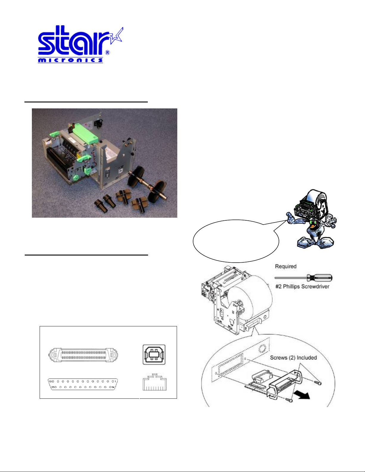
Assembly – Installing the Interface
Place the interface sub-assembly into the
interface slot as shown. Take care to be sure the
interface cartridge is seated properly into its
connector.
Using a #2 Phillips screwdriver, install the
mounting screws included with the printer.
Interface Type…
Parallel
USB
Starski says, “Place
unused parts in a
safe place for later
use.”
Quick Setup Guide
Serial
Ethernet
Assembly – Paper Roll Setup
It is necessary to adjust the paper roll holder for the width of the paper you use. If the setting position is incorrect, the
paper roll will be supplied improperly to the mechanism which in turn causes paper transport problem s. Thus, it is should
be properly adjusted.
The following table shows the paper roll
holder and paper core inner diameter range.
Paper roll Holder
Types
Paper roll Holder (1) 25.4 mm ± 1
Paper roll Holder (2) 50.8 mm ± 1
Paper roll Holder (3) 76.2 mm ± 1
Note 1) The unit is assembled for 1 inch paper
cores when shipped from the factory. Also, it is set
for a paper width of 111.5 ±0.5 (take-up width of
112 +0.5/-1) when the printer is shipped from the
factory.
Starski says, “The size of
the core used is related
to the thickness of the
Paper Core
Diameter Ranges
paper used.”
Roll Holder Size Paper Thickness
1” or 25.4 mm 65 to 100 µm
2” or 50.8 mm 100 to 150 µm
3” or 76.2 mm 100 to 150 µm
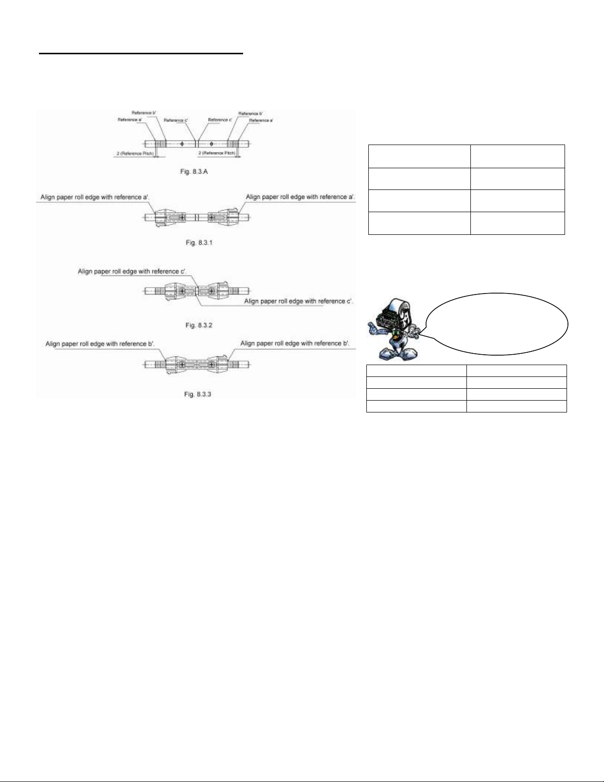
8.3 A
is a reference for the paper roll holder unit paper roll shaft position. Adjust or mount the paper roll holder unit for
the core diameter and width of the paper you intend to use.
8-3-1 Handling 111.5 mm Paper Width
See Fig. 8.3.1 for the paper roll holder setting position to handle paper widths of 111.5 ±0.5 mm.
Position the edge of the paper roll holder onto the central position of the references a and a'.
See the figure to assembly at the correct position.
Note 1) The paper roll holder is assembled to that position when shipped from the factory.
8-3-2 Handling 82 mm Paper Width
See Fig. 8.3.2 for the paper roll holder setting position to handle paper widths of 82 ±0.5 mm.
Position the edge of the paper roll holder onto the central position of the references c and c'.
See the figure to assembly at the correct position.
Note 1) In this case, be careful because the edge of the paper roll holder positioned on the reference is the opposite.
8-3-3 Handling 79.5 mm Paper Width
See Fig. 8.3.3 for the paper roll holder setting position to handle paper widths of 79.5 ±0.5 mm.
Position the edge of the paper roll holder onto the central position of the references b and b'.
See the figure to assembly at the correct position.
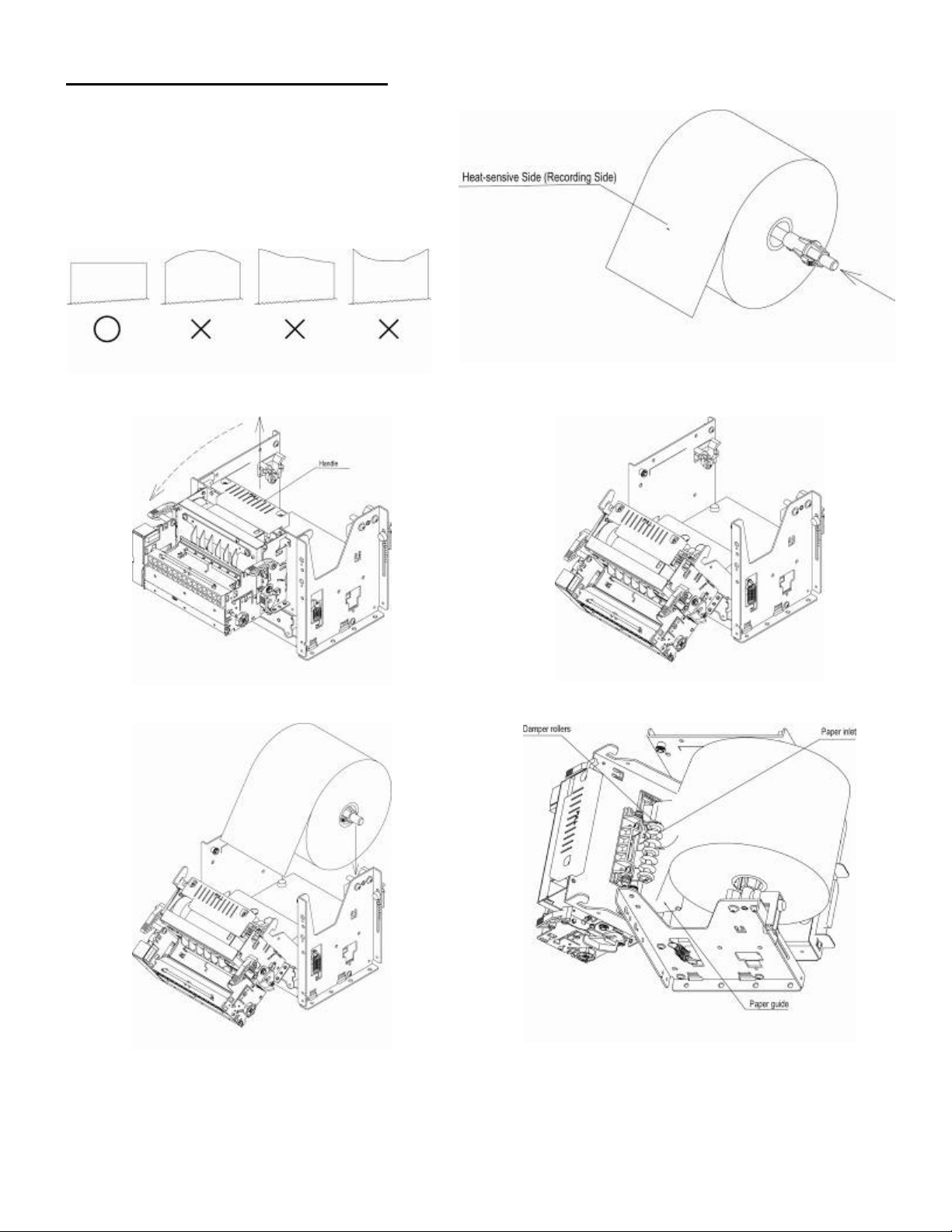
Assembly – Paper Roll Setup Continued
Once the paper roll holder is properly
configured for the roll to be used, simply insert
the roll holder into the paper core as show.
Be sure that the cut end of the paper roll is
properly cut to ensure proper paper loading.
To aid in the installation of the paper roll, the TUP900’s mechanism is hinged to the base of the
printer allowing the unit to fold open for easier access to the paper inlet path (see below)
Lift handle and pull unit forward.
In this position, it will be much easier to access
the paper inlet for loading of paper.
Position the paper roll as shown.
Slide the cut end of the paper roll into the paper
inlet being careful to feed the paper underneath
the damper rollers.
NOTE: The semi-auto paper loading of the TUP900 can sometimes cause the printer to enter an
error condition if paper is not allowed to feed smoothly into the paper inlet path. In the event of an
error, reset the printer by turning the power switch OFF and then ON again.
 Loading...