

Star Micronics TSP600 Installation Manual
Attaching the TSP600 vertical stand
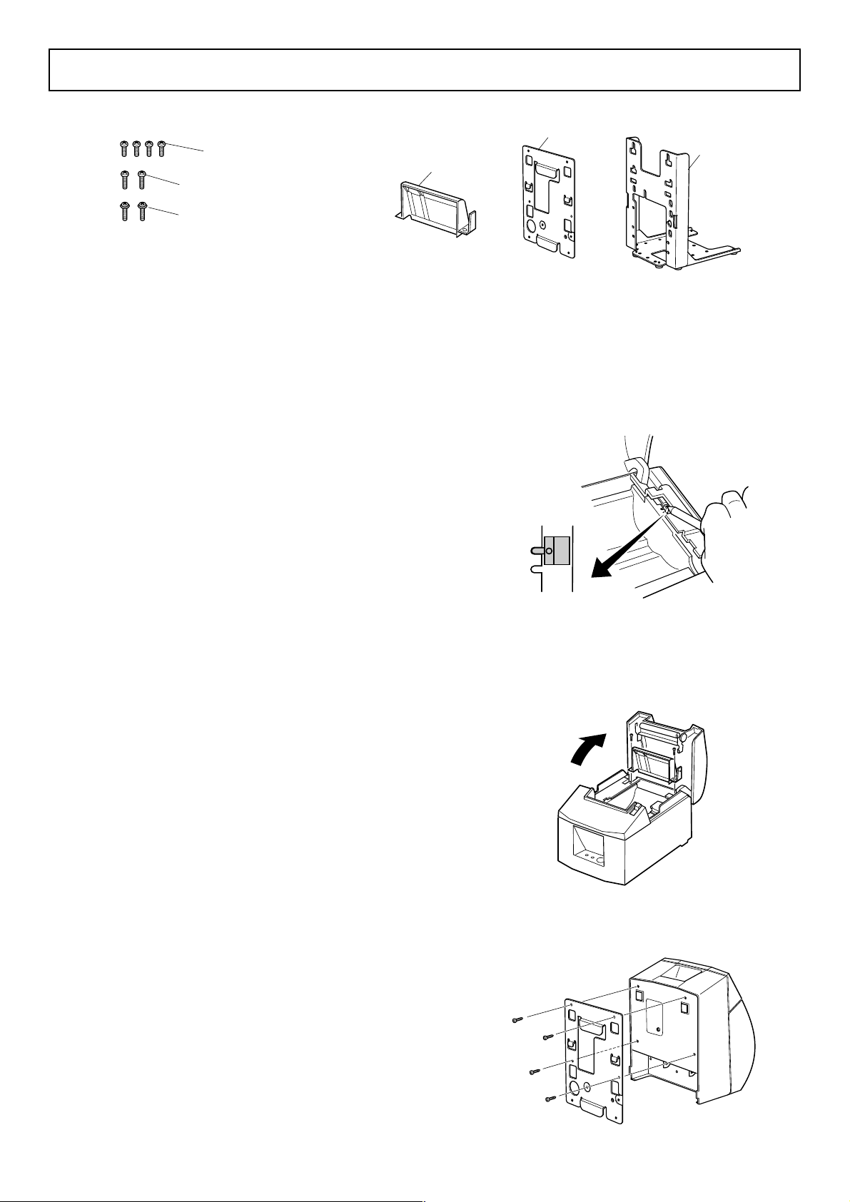
1. Unpacking : Confirm that all accessories are included.
M3 × 6 screws (4)
(for attaching the holder plate)
M3 × 8 screws (2)
(for attaching the paper guide B)
M4 × 8 screws (2)
(for attaching the stand)
2. Attachment procedures :
Note: Ensure that power that is supplied to the printer
and that all devices connected to the printer have
been switched OFF and that the cables have been
unplugged before starting the modification. If the
AC adapter is connected to the printer, unplug it
from the main socket.
The base for setting the stand should be within a
range of
2-1. Changing the position of the near end sensor
1 Push the cover open lever, and open the printer cover .
2 Press the sensor hole with the tip of a pen or any
other pointed-tip object and slide the Near End
Sensor to the Level 2 position shown in the figure.
Check that the protrusion is securely fit into the
groove.
±2° in reference to the horizontal direction.
Paper guide B
Holder plate
(
Level
)
2
Stand
2-2. Attaching the paper guide B
Attach the paper guide B to the printer. Then tighten
the two M3 screws that were supplied to secure it
in place.
2-3. Attaching the holder plate
Attach the holding plate to the printer. Then tighten
the four M3 screws that were supplied to secure it
in place.
fig.1 Changing the position of the near end sensor
fig.2 Attaching the paper guide B
fig.3 Attaching the holder plate
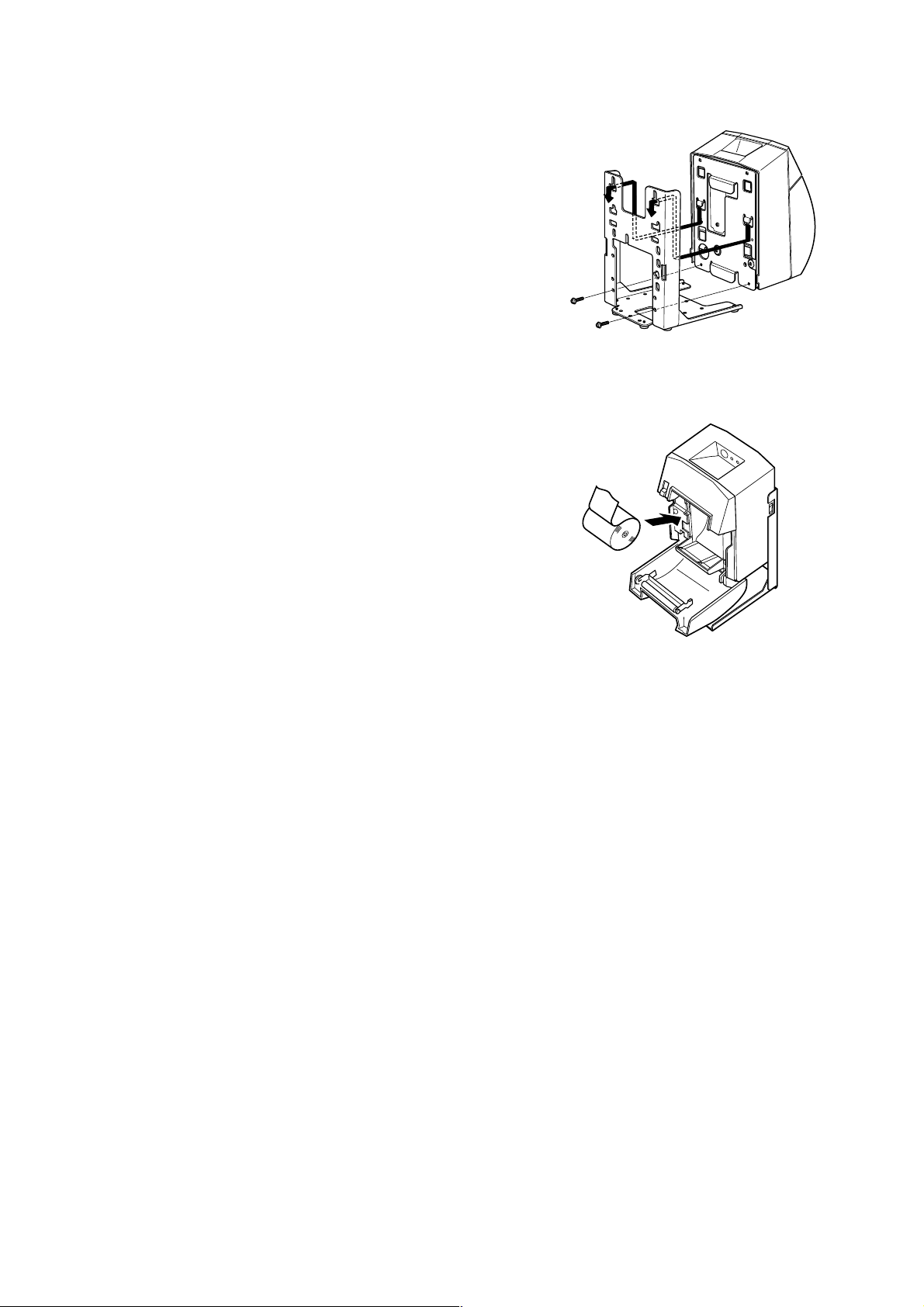
2-4. Setting the printer on the stand
Insert the two hooks on the holding plate through
the two holes on the stand. Three different positions
are available for insertion.Select the highest position.
Once the hooks have been inserted into the holes,
secure the printer on the stand using the two screws.
2-5. Setting the roll paper in place
1 Push the cover open lever, and open the printer cover .
2 Insert the roll paper as shown.
fig.4 Setting the printer on the stand
fig.5 Setting the roll paper in place
80871210 VS-T600
 Loading...