

Page 1

THERMAL UNIT PRINTER MECHANISM
TUP492-24
SPECIFICATION
AND
OPERATION MANUAL
Page 2

NOTICE
• All rights reserved. Reproduction of any part of this manual in any form whatsoever, without
STAR’s express permission is forbidden.
• The contents of this manual are subject to change without notice.
• All efforts have been made to ensure the accuracy of the contents of this manual at the time of
going to press. However, should any errors be detected, STAR would greatly appreciate being
informed of them.
• The above notwithstanding, STAR can assume no responsibility for any errors in this manual.
Copyright 1998 Star Micronics Co., LTD.
– 0 –
Page 3

CONTENTS
1. GENERAL DESCRIPTION ..........................................................................................................1
2. CONSTRUCTION ..........................................................................................................................2
2.1 Configuration .......................................................................................................................2
2.2 Principle of Operation..........................................................................................................2
3. GENERAL SPECIFICATIONS
4. PAPER ROLL SPECIFICATIONS
5. PRINTER SETTINGS
5.1 Switches and Buttons...........................................................................................................7
5.2 Setting the DIP Switches......................................................................................................8
5.3 Setting the EEPROM .........................................................................................................10
6. DISPLAYS AND FUNCTIONS
6.1 LEDs ..................................................................................................................................12
6.2 RESUME Button................................................................................................................12
6.3 Power Switch and Button Combinations ...........................................................................12
6.4 Sensor Adjusting Mode......................................................................................................13
6.5 Near-End Sensor ................................................................................................................13
6.6 Error Messages...................................................................................................................14
6.7 Near-End Sensor Position ..................................................................................................16
7. INTERFACE
7.1 Serial Interface (RS-232C or RS-422A) ............................................................................17
7.2 Parallel Interface ...............................................................................................................19
8. CUTTER
9. PRESENTER
10. CHARACTERS
10.1 Character Set......................................................................................................................22
10.2 Characters and Sizes...........................................................................................................22
11. POWER REQUIREMENTS
12. NOISE
13. STANDARDS
14. RELIABILITY
15. INSTALLING THE PAPER ROLL
16. INSTALLATION
17. MAINTENANCE
.............................................................................................................................................25
14.1 During operation ................................................................................................................26
14.2 During storage....................................................................................................................26
14.3 Allowable Static Electricity Level ....................................................................................27
14.4 Vibration Test.....................................................................................................................27
14.5 Drop Test ...........................................................................................................................27
14.6 Life Test .............................................................................................................................28
16.1 Installation precautions ......................................................................................................32
16.2 Other precautions ...............................................................................................................32
.................................................................................................................................17
.......................................................................................................................................20
.................................................................................................................................21
.............................................................................................................................22
.................................................................................................................................25
..............................................................................................................................26
....................................................................................................................7
..........................................................................................................................31
..........................................................................................................................36
....................................................................................................4
..............................................................................................5
...................................................................................................12
........................................................................................................23
............................................................................................29
Page 4

1. GENERAL DESCRIPT
The TUP492-24 printer is a line thermal printer and is used in various electronic equipment, such as
game machines, ATMs and information kiosks. TUP492-24 is equipped with a presenter which discharge and collect paper.
These printers feature the following:
1. High-speed printing: 2 in./sec (50 mm/sec)
2. High resolution: 8 dots/mm vertically, 8 dots/mm horizontally (approx. 200 dpi)
3. Silent operation
4. Paper roll size: max. 8-inch diameter
5. Choice of three types of interfaces (optional)
6. Presenter function
Display of Model Name
TUP4 9 2 D 24 NL
—
Equipped with no translucent sensor
Power supply voltage : DC 24 V
Interface
D: RS-232C
C: Parallel
K: RS-422A
Mechanism type
2: 40 digits
Printer type
9: Equipped with a guillotine-type full cutter and presenter
(discharge and collect)
TUP400 series thermal printer
– 1 –
Page 5

2. CONSTRUCTION
2.1 Configuration
The unit printer mechanism is constructed of the following components:
Unit printer mechanism Thermal printer Sensor
Thermal head
Drive Gear
Platen
MotorPresenter
Cutter (guillotine-type full cutter)
2.2 Principle of Operation
2.2.1 Drive and paper feed
The rotation of the stepping motor is transmitted to the gear, which turns the platen. The rotation of the platen generates friction between it, the thermal paper and the thermal head, therefore causing the paper to be fed.
2.2.2 Printer
Color appears on the thermal paper as the temperature of the thermal head’s heat-generating
element increases.
2.2.3 Presenter
The edge of the thermal paper stops just before the presenter’s ejector, the continuous feed of
the thermal paper creates a loop and after printing is finished, the paper is cut. Then, the paper is
fed out by the roller in front of the ejector (The DC motor rotates the roller). Detecting the paper
bottom end, the roller stops its rotation.
Frame Control and interface boards
Near-end sensor
When the fixed period of time passes, or the collection command is sent, the presenter collects
the paper.
– 2 –
Page 6
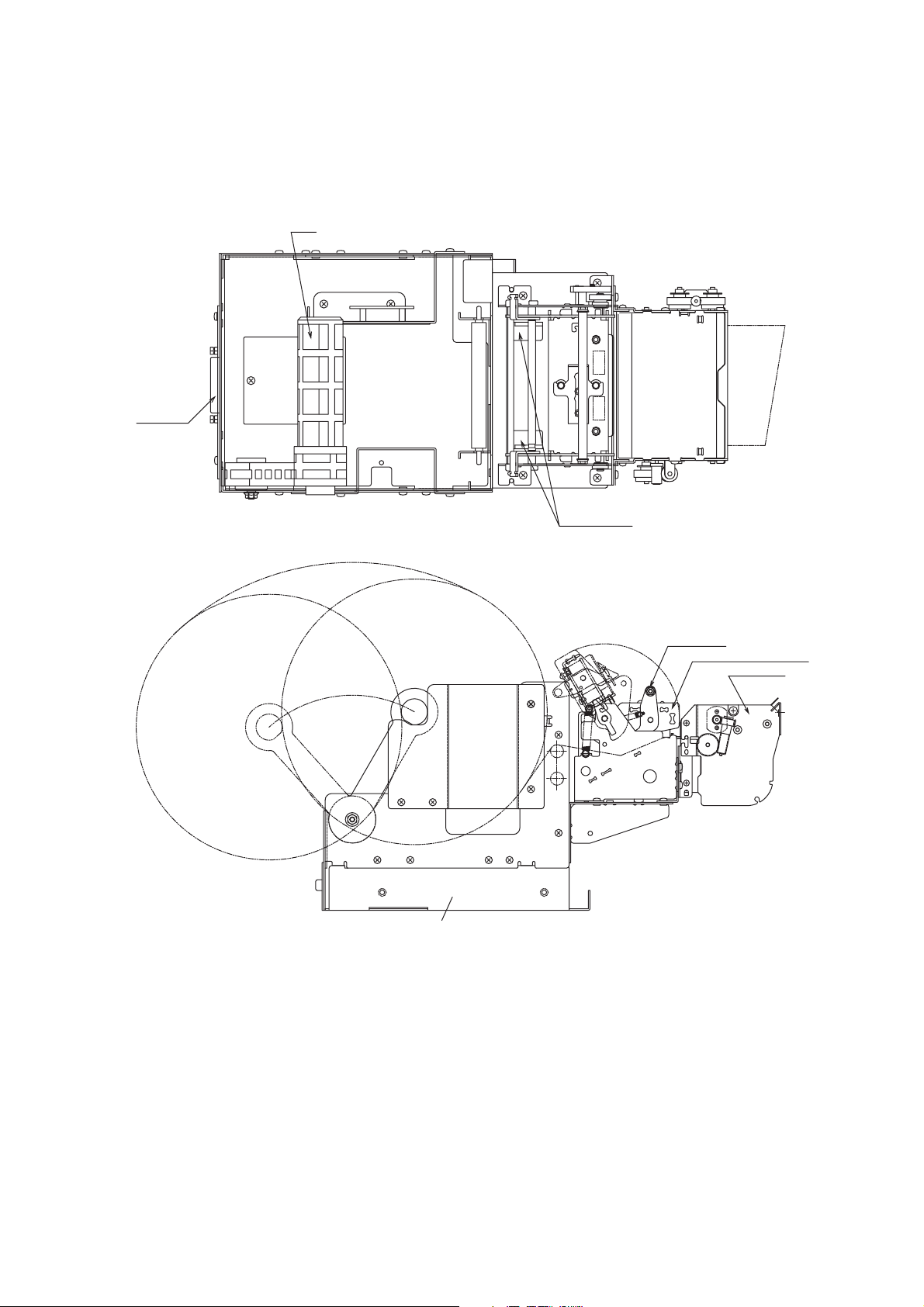
Exterior Vie w
Inter face
Arm
Paper guide
Head stay
Thermal mechanism
B
A
Frame (Inside is the main PCB and interface PCB)
Presenter
– 3 –
Page 7

3. GENERAL SPECIFICATIONS
Item Specification
Printing method Line thermal direct printing
Printing speed 50 mm/sec, 25 mm/sec
Printing area 80 mm wide (page mode), 75 mm wide (line mode)
Resolution 8 dot/mm (horizontal)
8 dot/mm (vertical)
Paper width 82.55 mm (3.25 in.)
Paper roll diameter Outer: max. 203 mm (approx. 8 in.)
Inner: 32 mm (approx. 1.26 in.)
+1
0
Characters ASCII
International character set
Katakana (Japanese syllabary)
Bar code
0
-2
Paper detection Paper-out detection using a reflecting photo sensor
Black mark detection using a reflecting photo sensor
Paper near-end detection using a reflecting photo sensor
Interface Serial (RS-232C or RS-422A (optional))
Parallel
Data buffer Approx. 8 KB
Auto cutter Guillotine-type full cutter
Power supply voltage DC 24 V ± 7%
Environment Temperature 5˚C to 40˚C
Relative humidity 25% to 80% (no condensation)
External dimensions 173 mm (W) × 355 mm (D) × 175 mm (H)
(without paper roll inserted)
173 mm (W) × 382 mm (D) × 254 mm (H)
(with 8-in. paper roll inserted)
Weight Approx. 3.45 kg
– 4 –
Page 8
4. PAPER ROLL SPECIFICATIONS
Item Specification
Paper type Normal heat-sensitive paper
Paper width 82.55 mm (3.25 in.)
Paper thickness 60 to 100 µ m
Core diameter Inner: 32 mm
Paper type Nippon Seishi TF50KS-E
0
–1
+1
0
Outer: 35 mm
+1
0
TF62KS-E
Shin Oji Seishi KF-730
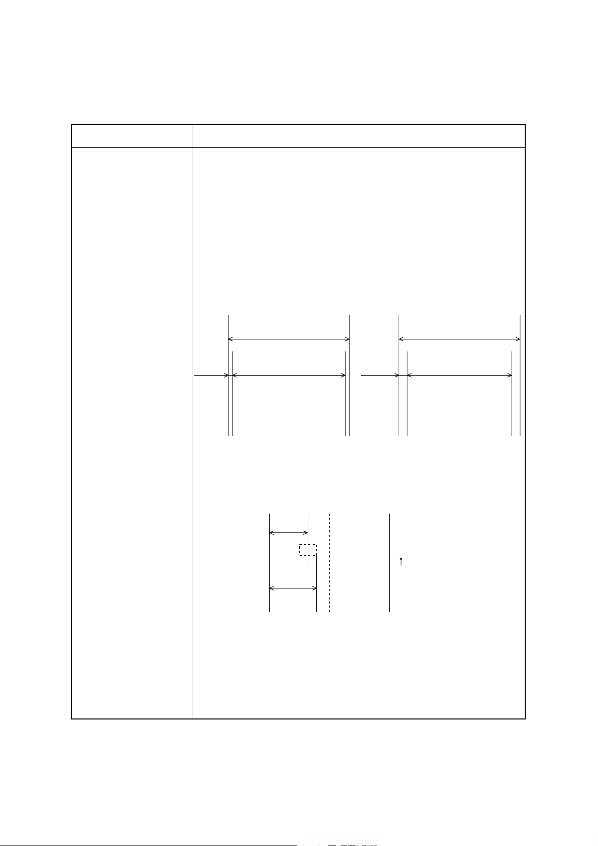
Printing area
82.55 mm
275 mm
80 mm
Printing area
(Page mode)
3.775 mm
Black mark Printing density Macbeth valve 1.2 or higher
Printing position
26 mm
82.55 mm
75 mm
Printing area
(Line mode)
Paper feed
Max. 36 mm
Printing side Back (opposite to the printed side)
Size Width: 10 to 20 mm
(center of the paper must be avoided)
Length: 3 to 10 mm
Reference position The end of the black mark should be positioned at
the front in the paper feed direction.
– 5 –
Page 9

Notes)
Use paper that is rolled inward.
●
●
Do not affix the end of the paper to the paper roller.
●
Paper jams may occur depending on the paper quality used and the pattern printed.
If the machine is turned off and left for a long time with paper caught in the thermal head, the
●
paper should be removed and inserted again.
●
Keep this machine on a level surface.
The roller may leave short marks in the end of the paper.
●
– 6 –
Page 10

5.PRINTER SETTINGS
5.1Switches and Buttons
The DIP switches and memory switches (EEPROM) are used to make the printer’s settings. In addition, the sensor adjusting button and RESUME button, which are not used for making printer settings,
are installed.
The sensor adjusting button is located on the paper-out and near-end sensor’s PCB (N.EPCB), and is
mainly used for adjusting the photo sensors, therefore, it is not used by the general user. The RESUME
button is located on the casing (near the LF motor), and is used to bring the printer back on line after it
goes off line (e.g. paper-out). For more details about the RESUME button, refer to “6. DISPLAYS
AND FUNCTIONS”.
The DIP switches are mounted to the interface’s PCB and can be changed by operating them from the
hole used for replacing the EPROM or by removing the interface’s PCB.
The number of DIP switches differs according to the type of interface.
Centronics: 1(4-bit)
RS-232C: 2 (10-bit and 4-bit)
RS-422A: 2 (8-bit and 4-bit)
The EEPROM is 1 word by 16 bits. The EEPROM is mounted on the main unit’s PCB and can be
changed with the commands.
– 7 –
Page 11
5.2 Setting the DIP Switches
All of the DIP switches have been set to ON at the time of shipping.
5.2.1 Serial Interface
a) DIP switch 1 (for both RS-232C and RS-422A)
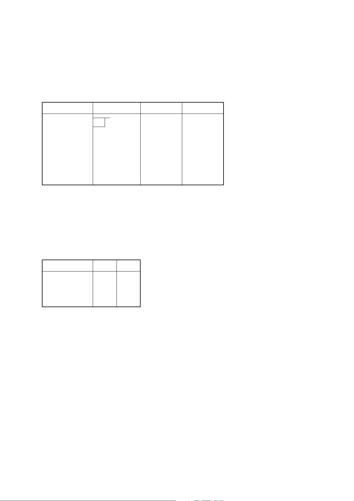
Switch position Function ON OFF
1-1 Baud rate
1-2
1-3 Handshaking DTR XON/XOFF
1-4 Data length 8 bits 7 bits
1-5 Parity Disabled Enabled
1-6 Parity Odd Even
1-7 DC1, 3 (*1) Disabled Enabled
1-8 Power on (*2)
*1 Only for the RS-232C (This setting is made with DIP switch 2 on the RS-422A.)
*2 For the power on function
1-8 ON 1-8 OFF
When DC1, 3 is disabled Select Select
When DC1, 3 is enabled Select Deselect
When addressable Deselect Select
Baud rate 1-1 1-2
2400BPS OFF OFF
4800BPS OFF ON
9600BPS ON ON
19200BPS ON OFF
– 8 –
Page 12
b) DIP switch 2 (only for the RS-422A)
SW 2-1 SW 2-2 SW 2-3 SW 2-4
DC1, 3 disabled ON ON ON ON
Address #1 OFF ON ON ON
#2 ON OFF ON ON
#3 OFF OFF ON ON
#4 ON ON OFF ON
#5 OFF ON OFF ON
#6 ON OFF OFF ON
#7 OFF OFF OFF ON
#8 ON ON ON OFF
#9OFFONONOFF
#10 ON OFF ON OFF
#11 OFF OFF ON OFF
#12 ON ON OFF OFF
#13 OFF ON OFF OFF
#14 ON OFF OFF OFF
DC1, 3 mode OFF OFF OFF OFF
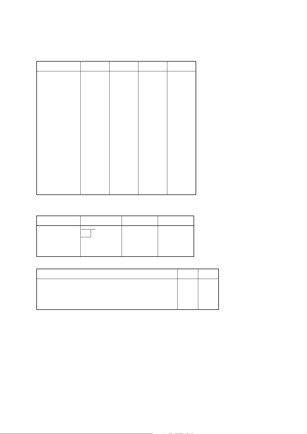
5.2.2 Parallel Interface
Switch position Function ON OFF
1-1 Mode
1-2
1-3 Not used
1-4 Not used
Mode 1-1 1-2
Compatibility mode ON ON
Nibble mode (without negotiation, without termination) OFF ON
Byte mode (without negotiation, without termination) ON OFF
Not used OFF OFF
– 9 –
Page 13
5.3 Setting the EEPROM
The following command from the host computer is used to make the EEPROM settings.
a) EEPROM settings command
<ESC> #N, n1 n2 n3 n4 <LF> <NUL>
N: Memory switch no.
n1 n2 n3 n4: Setting data
For more details, refer to “Programmer’s Manual”.
b) Memory switch 0
N = 0
n1: Always 0
n2: Always 0
n3: Always 0
n4: Mode select
0 Page mode (Default)
1 Line mode
c) Memory switch 1
N = 1
n1: Sensor select
n2: Start-position detect
n3: Zero style
n4: International character set
Parameter Setting 0 (Default) 1
n1 Sensor select Reflective sensor
Transmissive sensor
(Black mark)
n2 Start-position detect OFF ON
n3 Zero style Normal zero Slashed zero
n4 International character set See below
n4 Country n4 Country
0 USA 7 Spain #1
1 France 8 Japan
2 Germany 9 Norway
3 UK A Denmark #2
4 Denmark #1 B Spain #2
5 Sweden C Latin America
6 Italy
– 10 –
Page 14

d) Memory switch 2
N = 2
n1: Always 0
n2: Always 1
n3: Always 0
n4: Printing speed
0 50 mm/sec. (Default)
1 25 mm/sec.
e) Memory switch 3
N = 3
n1: Always 0
n2: Character table
0 Normal (Default)
1 Katakana
2IBM
3IBM
n3: Print column
0 40 column (Default)
1 50 column
n4:
0 <CR> Disabled Paper feed 4 mm (Default)
1 <CR> Disabled Paper feed 3 mm (Default)
2 Same as <LF> Paper feed 4 mm
3 Same as <LF> Paper feed 3 mm
f) Memory switch B
N = B
n1: Always 0
n2: Presenter
0 Not installed (TUP452)
1 Installed (TUP482)
n3: Always 0
n4: Always 1
– 11 –
Page 15

↓
↓
6. DISPLAYS AND FUNCTIONS
The LEDs and RESUME button are mounted on the NEPCB.
6.1 LEDs
LED Function
HU
PE
ERR
6.2 RESUME Button
When no paper is inserted, insert more paper, then press this button to automatically feed the specified
length of paper (approx. 80 mm when the presenter is installed or approx. 30 mm when it is not). After
the paper is cut, the printer will go back on line.
6.3 Power Switch and Button Combinations
The following settings can be made by pressing either the RESUME button or the sensor adjusting b utton at the same time that the power switch is turned on.
<RESUME button and power switch>
Buzzer LED Function
One beep HU lights up
Two beeps PE lights up
Lights up when errors occur
(For more details, refer to “6.6 Error Messages”.)
2 sec.
Release the RESUME button to execute a HEX dump.
[*1]
Release the RESUME button to execute a test print. [*2]
[*1] The HEX dump mode remains valid until the power is turned off.
[*2] The printer continues the test print until the power is turned off.
<Sensor adjusting button and power switch>
Buzzer LED Function
One beep HU lights up
2 sec.
[*3] Do not continue pressing the sensor adjusting button for more than two seconds.
Note) The Line and Page modes cannot be chosen with the panel buttons; these modes can only be
chosen with commands.
Release the sensor adjusting button to start sensor
adjusting mode. [*3]
– 12 –
Page 16

6.4 Sensor Adjusting Mode
a) Reflecting sensor (black mark sensor)
●
Insert the paper in front of the sensor mechanism so that a black mark is not positioned in front of
the sensor.
●
Adjust the reflecting sensor controller VR4 on the PCB until the HU LED lights up.
b) Paper-out sensor
Insert the paper in front of the sensor mechanism so that a black mark is not positioned in front of
●
the sensor.
Adjust the paper-out sensor controller VR3 on the PCB until the PE LED lights up.
●
6.5 Near-End Sensor
Selecting the open frame setting with memory switch B enables near-end sensors A and B. It is possible to determine the state of near-end sensors A and B by outputting the <EOT> command to the
printer. (This is only possible when a serial interface is used.) Refer to “Programmer’s Manual”.
– 13 –
Page 17

6.6 Error Messages
It is possible to determine the type of error occurring by observing the printing results and which LED
lights up.
a) Recoverable errors
The printer goes off line when these errors occur.
To resume operation, remove the cause of the error, then press the RESUME button.
Error Cause
LED
ERR HU PE
Head up error The head is raised. On
Paper-out error No paper is inserted. On
Label size error The paper size differs from the measured size. On
b) Unrecoverable errors
The printer goes off line when these errors occur.
Operation of the printer will be resumed by pressing the resume button after the cause of the unrecoverable error is removed.
LED
Error Cause
ERR HU PE
Command error There is an error in the command. On
Cutting error The paper is not cut properly. On On
Transmission error *1 There is an abnormality in the received data. On On
Paper jam error *2 The paper is not fed up to the sensor. On On On
*1 Valid only with the serial interface
*2 If the paper is jamed inside the presenter
1
Paper Jam, Case 1: Removing paper from inside the presenter.
(Procedure)
1) If there is a paper jam at the Open/Close plate, lower
the Open/Close plate if it is in the up position. (If it is
in the down position, leave it down.)
2) Remove the jammed paper from the space below the
presenter unit.
Note) When lowering the Open/Close plate, be careful
not to bend the PET film unit.
– 14 –
Page 18

2
Paper Jam, Case 2: Removing paper from near the cutter.
(Procedure)
1) When paper is jammed inside the cutter , if it cannot be
removed by the procedure in Case 1, take out the
screws on both sides of the presenter, as shown in the
figure.
2) Slide the presenter along the * part in the figure, separating the presenter and the cutter, then remove the
jammed paper.
3) After removing the jammed paper, slide the presenter
back, following the procedure in 2) in reverse order,
then fasten it in its original position using the screws.
Note) When fitting the presenter with the cutter in 3)
above, be careful not to get the two wires sho wn in
the figure caught between the presenter and cutter.
c) Other errors
Data errors (<ESC> “PC” command: defines character and bar code data)
●
A data error will occur if an invalid character or bar code type is selected or if the print result
extends outside the print area. When a data error occurs, all commands become invalid (character
strings and bar codes are not printed). Howev er, the printer will not go off line and the LEDs will
not light up.
– 15 –
Page 19

6.7 Near-End Sensor Position
<Technical Specifications>
The near-end sensors can be moved a maximum of 5 mm to the right or left by moving the near-end
sensor PCB.
Slightly loosen the three screws (without removing them) used to install the PCB, then move the PCB
to the desired position. After making sure that the PCB fits properly (i.e. it is not loose), tighten the
three screws. (Do not break the PCB.)
Near-end sensor NEA
Near-end sensor NEB
Near-end sensor PCB
Screw
Square hole
Side frame
Can be moved a maximum
of 5 mm to the right and left
* The near-end sensors are mounted on the back of the PCB.
– 16 –
Slot
Page 20

7. INTERFACE
Three interface types are available: parallel, serial RS-232C or serial RS-422A. Any of these interfaces
can be used by installing the corresponding PCB.
7.1 Serial Interface (RS-232C or RS-422A)
RS-232C
Item Specification
Data transfer method Asynchronous serial interface
Data transfer rate 2400, 4800, 9600, 19200
Start bit: 1
Data bit: 7 or 8
Odd, even or no parity
Stop bit: 1
Signal polarity Mark = logic “1” (–3 V to –15 V)
Space = logic “0” (+3 V to +15V)
Connector Pin Assignment (D-SUB 25 pin)
Pin No. Signal Name IN/OUT Function
1 F-GND — Frame ground
2 TXD OUT Transmit data
3 RXD IN Receive data
4 RTS OUT Send request signal. There is a space when the printer is
ready to receive.
5 CTS IN There is a space when the host computer is ready to
send. However, this signal is not checked by the printer.
6 N/C Not used
7 S-GND Signal ground
8 ~ 10 N/C Not used
11 RCH OUT There is a space when the printer is ready to receive.
Same as pin 20.
12 N/C Not used
13 S-GND Signal ground
14 FAULT OUT There is a mark when an error is occurring in the printer.
15 Multi-TXD OUT Send data for multi printer
16 Multi-DTX IN Receive data for multi printer
17 ~ 19 N/C Not used
20 DTR Data terminal ready signal. There is a space when the
printer is ready to receive.
21 ~ 25 N/C Not used
– 17 –
Page 21

RS-422A
Item Specification
Data transfer method Asynchronous serial interface
Data transfer rate 2400, 4800, 9600, 19200
Start bit: 1
Data bit: 7 or 8
Odd, even or no parity
Stop bit: 1
Signal polarity Mark = logic “1” (–)
Space = logic “0” (+)
Connector Pin Assignment
Pin No. Signal Name IN/OUT Function
1 F-GND Frame ground
2 ~ 6 N/C Not used
7 S-GND Signal ground
8 N/C Not used
9 SD (+) OUT Send data
10 SD (–) OUT Send data
11 ~ 12 N/C Not used
13 S-GND Signal ground
14 ~ 16 N/C Not used
17 RD (+) IN Receive data
18 RD (–) IN Receive data
19 CS (+) IN There is a space when the host computer is ready to
send. However, this signal is not checked by the printer.
20 ~ 22 N/C Not used
23 CS (–) IN There is a space when the host computer is ready to
send. However, this signal is not checked by the printer.
24 RS (+) OUT Send request signal. There is a space when the printer is
ready to receive.
25 RS (–) OUT Send request signal. There is a space when the printer is
ready to receive.
– 18 –
Page 22

7.2 Parallel Interface
Item Specification
Method Centronics
Data transfer rate 1000 to 6000 cps
Synchronization method External supply strobe pulse
Handshaking By A
CK and BUSY signals
Logic level TTL-compatible
Connector Pin Assignment
Pin No. Signal Name IN/OUT Function
1 STR
OBE IN Normally HIGH. Data reading starts after this signal
becomes LOW.
2 ~ 9 DATA 1 ~ 8 IN Data. HIGH for “1”, LOW for “0”.
10 A
CK OUT Turned ON when data acquisition is complete.
11 BUSY OUT Reception of data is possible when this signal is LOW;
reception is not possible when HIGH.
12 PAPER OUT OUT Becomes HIGH when no paper is inserted.
13 SELECTED OUT Becomes HIGH when the printer goes on line.
14 ~ 15 N/C Not used
16 SIGNAL GND Signal ground
17 CHASSIS
Printer frame ground
GND
18 +5 V +5 V for external equipment (50 mA max.)
19 ~ 30 TWISTED
Return signal for various signals
P AIR RETURN
31 RESET
32 ERR
OR OUT Becomes LOW when the printer cannot function.
IN Initializes the printer when LOW.
33 EXT GND Ground terminal for external equipment
34 ~ 35 N/C Not used
36 — Always HIGH
– 19 –
Page 23

8. CUTTER
Item Specification
Method Guillotine-type full cutting
Drive method DC motor
Installation Attached to the mechanism with screws
Supply Thickness of one sheet of paper: 60 to 100 µ m
Minimum cutting length 25.4 mm (no presenter)
80 mm (equipped with presenter)
Life (standard paper) 300,000 times
Paper debris must be removed.
Error An error occurs if the cutter has not returned to the home position within
the specified time.
Notes) If the cutter is not located at the home position when an error has occurred, it can be returned
to the home position by removing the cause of the error and turning the power off, then on
again.
The cutter can also be returned to the home position by turning off the power, inserting a
screwdriver into the hole on the side of the cutter, then rotating the motor until the cutter is
returned to the position which is believed to be the home position.
– 20 –
Page 24

9. PRESENTER
Item Specification
Possible sheet length Approx. 80 mm (min.)
Approx. 300 mm (max.)
Operation sequence
(viewed from the
operator’s side)
a. The paper is not ejected during printing.
b. The cutter cuts the end of the paper after printing is completed.
c. The presenter’s roller rotates for 5 seconds, which causes the sheet to
be ejected from the exit. The sheet stops when the end leaves the
roller.
d. The next printing step starts when the sheet is removed by the opera-
tor.
e. If the sheet is not removed within 5 seconds, the roll begins to rotate.
If the status end request (EOT) is sent from the host computer while
the sheet is remains at the exit, the host computer will return to status
E5.
– 21 –
Page 25

10. CHARACTERS
10.1 Character Set
ASCII
Katakana (Japanese syllabary)
International character set
10.2 Characters and Sizes
(Width and length of 1 dot = 0.125 mm (1/8 mm))
1. Page mode
Character face Print size (length × width)
Small characters 16 × 8 dots
Standard characters 24 × 16 dots
Bold characters 32 × 24 dots
OCR-B 24 × 16 dots
Full-size Kanji 24 × 24 dots
2. Line mode
Character face Print size (length × width)
IBM Block 24 × 12 or 32 × 12 dots
Other ANK 24 × 12 dots
Full-size Kanji 24 × 24 dots
Half-size Kanji 24 × 12 dots
– 22 –
Page 26

11. POWER REQUIREMENTS
The input voltage shall be DC 24 V ± 7% (rated 2.5 A, less than 6 A/15 sec.). The current used when
solid printing is performed is shown below.
Block 1 (384 dots)
12A
8A
T T
0.5A 0.5A
Cycle 2.5ms
12A
Block 2 (256 dots)
8A
T T
Item Specification
T (weld time) approx. 550 ms (25˚C, standard density)
Max. 800 ms depending on the conditions
Current (during solid
printing)
Item Specification
Recommended power
supply
Peak current: 12 A max.
Average current: 6.6 A max.
12 × 0.8 + 8 × 0.8 + 0.5 × (2.5 – 0.8 × 2)
2.5
For 100 or 120 V Star Micronics Power Supply Unit SLS-060P-50
(Part number: 87393030)
For 230 V Star Micronics Power Supply Unit SLS060PH-50A
(Part number: 87393090)
– 23 –
Page 27

Power connector
1
2
3
4
JST. VHR-4N
UL1007 AWG18
Recommended power – unit junction cable
Unit junction connector
AMP 1-480425-0
Unit power cable
1: 24V
2: 24V
3: GND
4: GND
1
2
3
4
AMP 1-480426-0
– 24 –
Page 28

12. NOISE
Item Specification
Measurement standard = ANSI 1.29 (DIN45, ISO7779)
Average sound pressure at 1 m 50 dB or less
13. STANDARDS
Safety standards
1. UL (RU)
2. CSA
– 25 –
Page 29

14. RELIABILITY
14.1 During operation
Temperature: 5˚ ~ 40˚C
Humidity: 25% RH ~ 80% RH (no condensation)
Operating temperature and humidity ranges
% RELATIVE HUMIDITY
100
90
80
70
60
50
40
30
20
10
-20-100 1020304050607080
°C ENVIRONMENTAL
TEMPERATURE
Notes) When the environmental temperature is too high, the thermal head temperature sensor is acti-
vated and the printer stops operating.
14.2 During storage
Temperature: –20˚C ~ 60˚C
Humidity: 10% RH ~ 90% RH (no condensation)
– 26 –
Page 30

14.3 Allowable Static Electricity Level
Quality control
test specifications
±
±
±
Direct discharge Element allowable level
(self-printing)
8 kV (*1)
No fracturing of elements allowed ± 15 kV
Indirect discharge Element allowable level
(self-printing)
Checker connection allowable le vel
(continuous printing)
15 kV
3 kV (*2)
Direct discharge error: ≤ 5% (*1) ±10 kV test is also performed.
Indirect discharge error: 0% (*2) ±5 kV test is also performed.
Notes)
●
Use SLS-060P-50 (Sanken) as the power source.
The reference data is shown in the table above; this data may differ depending on the instal-
●
lation conditions.
14.4 Vibration Test
Item Specification
Frequency 7 ~ 100 ~ 7 Hz (sweeping: 2.5 minutes)
Amplitude 15.3 ~ 0.07 mm
Gravity 1.5 G (constant)
Vibration direction and
time
1 hour in each direction: X, Y and Z
Total of 3 hours
Packing As small as possible
14.5 Drop Test
Item Specification
Drop height 80 cm
Drop sequence One corner, three edges and six surfaces
Packing As small as possible
– 27 –
Page 31

14.6 Life T est
MCBF
Item Specification
No. of printed lines 5 million lines (excluding the thermal head life)
Auto cutter 300,000 cutting operations (One sheet of paper should be less than 85 µm.)
Thermal head 5 × 10
7
pulses or a printing distance of 30 km
Notes)
● The thermal head life given above is applicable for cases when standard paper is used.
● Printing continuously at a print ratio of less than 12.5% increases the resistance of the ther-
mal head’s heat-generating element by more than 15% of the initial value.
● Excluding damages caused by dust, foreign objects etc.
● Missing dot ratio maximum of 0.5% over 50 km.
– 28 –
Page 32

15. INSTALLING THE PAPER ROLL
OPEN
Lever
Arm
Cutter’s guide
Paper roll
• Remove the arm from the frame
and install the paper roll.
• Make sure that the end of
the paper is sharply cut.
Pass the paper over the damper shaft, pass it under the thermal head, then insert the paper between cutter guides. Double check that the paper is inserted into the cutter by looking into the small wholes on
the upper cutter guide. Feed the paper until the end enters the presenter’s roller.
– 29 –
Page 33

PRESS
Firmly press the areas indicated with crosshatches
on the thermal head until the lever is reset.
Carefully place the paper roll on the frame, then wind the roll to remove any slack in the paper. (Incorrectly installing the paper roll may bend the frame or cause a paper jam.)
RESUM
E
Press the RESUME button.
– 30 –
Page 34

16. INSTALLATION
Installation procedure
Install the printer using four M4 bolts as shown in the illustration below. (Refer to the diagram of the
“Installation Hole Dimensions”.)
Unit printer
Metal base
M4
– 31 –
Page 35

16.1 Installation precautions
1. Install the printer on a level surface. (Consult with a representati v e when installing the printer at an
angle.)
2. Be sure that there is plenty of space around the printer. (Refer to the diagram of the “External
Dimensions”.)
3. Since the thermal head is very hot, carefully examine where the printer is installed. (When a fan is
used to provide ventilation, be very careful of dust since it can damage the thermal head.)
4. Although this printer is made of plated steel sheets, the ends are not plated.
16.2 Other precautions
1. Correctly insert the paper before printing.
2. Do not use or store this printer in a dusty or oily environment or in a place containing a large
amount of iron.
3. Remove any dust, paper particles, etc. using either a soft brush or a cloth dampened in alcohol.
4. Do not apply a strong force to the printer. Otherwise, the frame may bend causing the printer to
malfunction.
5. The printer should only be used in the specified environmental conditions (temperature, humidity,
etc.) and not subject to sudden environmental changes. When sudden environmental changes
occur, the printer should be kept in the new environment for approximately 30 minutes before it is
used.
6. Do not use the printer if condensation has formed on it.
– 32 –
Page 36

5
74
6
204 146
349
2.8
82.5(PAPER WIDE)
73.3
10319
148
164.2
External Dimensions
– 33 –
(Unit: mm)
Page 37

120˚
45˚
266
253
204
199
175
162
159
151
80
19
72.4
382
max ø203
±0.15
13.7
±0.1
19
123.8
+0.03
2-3.7
493
0
– 34 –
(Unit: mm)
Page 38

Installation Hole Dimensions
Using four M4 bolts, install the printer from the bottom as shown in the illustration below.
Front
16
72.4115±0.1
4-M4
Back
130±0.1
View A (rear surface)
(Unit: mm)
– 35 –
Page 39

17. MAINTENANCE
Regular maintenance is very important since minute debris of thermosensible paper sticking to the
platen may cause slipping of the paper feeder. Maintenance should be made as follows:
Maintenance Timing:
Generally, TUP series should be maintained every time after using 8 rolls of 8 inch ø Star Standard
Spec paper roll, or 6 month.
Maintenance Procedures:
1. Make sure that the power supply is turned off before starting the maintenance procedures.
2. Wipe and rub the platen gently with a dry soft cloth to remove all debris stuck on the platen surface. (Turn the platen around to remove debris from all the surface.)
Take enough care not to touch the gears and the cutter guide when wiping the platen to avoid any
*
bodily injury.
Avoid wiping a same spot of the platen continuously, otherwise it may cause deformation of the
*
platen.
Wash your hands thoroughly before touching the platen.
*
Platen
Cutter guide
Dry soft cloth
– 36 –
Page 40

3. Remove the dirt from the thermal head using a cotton bud or soft cloth dipped in alcohol.
4. Remove all dirt, dust or paper debris, etc. adhering to the sensors (particularly the reflector type
sensors) of the thermal mechanism and the presenter.
Note) For the presenter’s paper sensor, take out the screws in the presenter cover on the side as
shown in the figure below, remove the cover, then remove the dust from above. Also, after
maintenance, return the presenter cover to its original position and fasten it with the screws
which were taken out before.
Presenter Cover
Screw
Paper sensor
– 37 –
Page 41

HEAD OFFICE
ELECTRONIC PRODUCTS DIVISION
STAR MICRONICS CO., LTD.
536 Nanatsushinya, Shimizu,
Shizuoka, 424-0066 JAPAN
Tel : 0543-47-0112
Fax: 0543-48-5271
Please access the following URL
http://www.star-micronics.co.jp/service/sp_sup_e.htm
for the lastest revision of the manual.
OVERSEAS SUBSIDIARY COMPANIES
STAR MICRONICS AMERICA, INC.
70-D Ethel Road West,
Piscataway, NJ 08854 U.S.A.
Tel : 732-572-9512
Fax: 732-572-5095
Distributed by
STAR MICRONICS U.K. LTD
Star House, Peregrine Business
Park, Gomm Road, High Wycombe,
Bucks, HP13 7DL, U.K.
Tel : 01494-471111
Fax: 01494-473333
Printed in Japan, 80874275
 Loading...