

Page 1
80822476 IFTBD400
Installing the interface board
“This device complies with Part 15 of the FCC Rules. Operation is subject to the following two conditions: (1) This device may not cause
harmful interference, and (2) this device must accept any interference received, including interference that may cause undesired operation.”
This equipment has been tested and found to comply with the limits for a Class A digital device, pursuant to Part 15 of the FCC Rules. These
limits are designed to provide reasonable protection against harmful interference when the equipment is operated in a commercial environment.
This equipment generates, uses and can radiate radio frequency energy and, if not installed and used in accordance with the instruction manual,
may cause harmful interference to radio communications. Operation of this equipment in a residential area is likely to cause harmful interference
in which case the user will be required to correct the interference at his own expense.
For compliance with the Federal Noise Interference Standard, this equipment requires a shielded cable.
This statement will be applied only for the printers marketed in U.S.A.
This digital apparatus does not exceed the Class A limits for radio noise emissions from digital apparatus set out in the Radio Interference
Regulations of the Canadian Department of Communications.
Le présent appareil numérique n’émet pas de bruits radioélectriques dépassant les limites applicables aux appareils numériques de la classe A
prescrites dans le Règlement sur le brouillage radioélectrique édicté par le ministère des Communications du Canada.
The above statement applies only to printers marketed in Canada.
Federal Communications Commission Radio Frequency Interference Statement
Statement of The Canadian Department of Communications Radio Interference Regulations
The interface board is an option for the compact size thermal printer
TSP400/TUP400 series. When installing the interface board, please use
the following procedure.
Interface Board Applicable printer
IFTBD400D
IFTBD400C
.........
IFTBD400K
IFTBD400V2D
IFTBD400V2C
IFTBD400K
RS-232C TSP412
........
Parallel TSP442
RS-422A TUP452
........
TUP482
...
RS-232C TUP492
....
Parallel TUP452V2..without presenter
........
RS-422A TUP482V2..with presenter
without auto cutter
.......
with auto cutter
.......
without presenter
.......
with presenter
.......
.......
with document capture
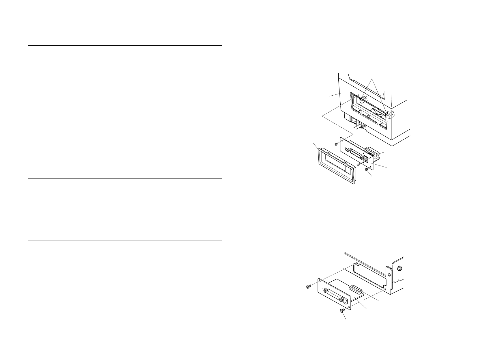
4. Secure the interface board using the three screws.
5. Replace the interface cover firmly.
Interface board PCB guide
Printer
Interface cover
Connector
Interfaceboard
Screws(3)
Installation
(
TUP400 Series
)
1. Make sure that the power cord is unplugged.
2. Insert the interface board so that it connects with the connector of the
control board in the printer.
3. Secure the interface board using two screws.
Installation
(
TSP400 Series
)
1. Make sure that the power cord is unplugged.
2. Remove the interface cover of the printer.
Note: No screws have been used.
3. Position the interface board in the PCB guide as shown in the
illustration, so that the components on the interface board face
upwards. Slide the interface board in until it is firmly seated.
Note: Insert the interface board so that it connects with the
connector.
Connector
Interface board
Screws(2)
 Loading...