

Page 1

Thermal Printer
TSP400
Series
TUP400
Programmer’s Manual
Page 2

Page 3

TABLE OF CONTENTS
1. OUTLINE............................................................................................1
2. Memory Switch and DIP Switch.........................................................3
2-1. Memory Switch............................................................................3
3. Display panel and functions ................................................................4
3-1. LED.............................................................................................. 4
3-2. Switches .......................................................................................4
3-3. Power switch and ON LINE/FEED switch combinations ...........4
3-4. Sensor adjustment mode ..............................................................5
4. SERIAL INTERFACE .......................................................................... 6
4-1. Interface Specifications................................................................6
4-2. Interface Circuit ...........................................................................7
4-2-1. RS-232C Interface .............................................................7
4-2-2. RS-422A Interface.............................................................7
4-3. Connectors and Signal Names .....................................................8
4-3-1. RS-232C Interface .............................................................8
4-3-2. RS-422A Interface.............................................................9
4-4. Interface Connections ................................................................ 10
4-5. Data Protocol..............................................................................11
4-5-1. DTR/DSR mode ..............................................................11
4-5-2. X-ON/X-OFF mode.........................................................13
4-5-3. STX-ETX mode...............................................................14
4-6. Error Status ...............................................................................16
5. PARALLEL INTERFACE..................................................................18
5-1. Interface Specifications..............................................................18
5-2. Interface Timing.........................................................................18
5-3. Connectors and Signal Names ...................................................19
6. PERIPHERAL UNIT DRIVE CIRCUIT ............................................21
6-1. Errors..........................................................................................23
7. CONTROL CODES/PAGE MODE.................................................... 24
8. CONTROL CODES/LINE MODE .....................................................61
8-1. Line Mode Command Summary................................................61
8-2. Command Specification .............................................................65
9. CHARACTER CODE TABLES.......................................................99
10. Automatic Cutter .............................................................................108
11. Presenter’s memory switch settings ................................................ 109
12. TSP LABEL ....................................................................................110
Page 4

1. OUTLINE
The TSP400 series is ideal for printing text, bar code and graphics.
The TSP400 series has the following features:
1. extremely quiet and fast printing (50 mm/sec.) using the direct line thermal
printing method
2. a straight paper path, which prevents paper jams and is ideal for label printing
3. support for many bar code types
(UPC, JAN/EAN-8, JAN/EAN-13, CODE 39, IFT 2 OF 5, CODE 128, CODE
93, NW-7)
4. a black mark sensor that detects the top of the page
5. a transmissive sensor that detects the gap between labels (no black mark is
necessary)
6. a large-diameter (115 mm) roll
7. a wide selection of interchangeable interfaces (RS232C, Centronics Parallel,
RS422A)
8. an installed heavy-duty and reliable cutter (TSP442 only)
9. enclosed utility software (TSPLABEL) that makes it easier to design and print
bar code labels
10.a memory switch that enables a wide selection of printer default settings and
easy setup using the enclosed utility software (TSPSETUP)
The printer has two different software modes which can be selected using the
memory switch. In order to enable changed memory switch settings, turn the
printer OFF and ON again or send printer reset command (<ESC>“?”) to the
printer.
(Factory setting: Page Mode)
Page Mode:
Code <ESC> “#0,0000” <LF> <NUL>
Hex 1B 23 30 2C 30 30 30 30 0A 00
Ideal for bar code label, graphics and text data printing.
Can locate and rotate bar code and text. Accepts a non-compressed BMP file so
that the printer can import and print a BMP file which is scanned or edited in
Windows applications.
– 1 –
Page 5

Line Mode:
Code <ESC> “#0,0001” <LF> <NUL>
Hex 1B 23 30 2C 30 30 30 31 0A 00
This mode is compatible with Star Receipt printers, such as the SP300 and SP200
series.
For improvement purposes, the descriptions and specifications in this manual are
subject to change without notice.
– 2 –
Page 6

2. MEMORY SWITCH AND DIP SWITCH
Functional settings are made using the printer’s EEPROM memory switches and
the DIP switches located on the interface board.
2-1. Memory Switch
Each memory switch is a 16-bit word stored in EEPROM.
The printer is shipped with the factory setting which is made in accordance with
its product type.
For the detailed functions and the settings of the Memory switches, please refer
to "Chapter 7 and 8".
The factory settings are shown in the table below.
hctiwsyromoM214PST244PST284PUT
0#000000000000
1#000000000000
2#000000000000
3#000000000000
B#--1010
2-2. DIP Switch
For the detailed functions and the settings of theDIP switches, please refer to
"Installation manual".
– 3 –
Page 7

3. DISPLAY PANEL AND FUNCTIONS
3-1. LED
LED Function
POWER Lights up when the printer is turned on
HEAD UP
NO PAPER Lights up when an error occurs (Refer to 6-1 Errors.)
ERROR
ON LINE Lights up when the printer is on line; goes off when the printer
is off line; lights up when the head temperature is too high
3-2. Switches
Switch Function
ON LINE Switches between on line and off line
FEED Enable starting position: Feeds the paper to the next starting
position
Disable starting position: Feeds the paper while pressed
3-3. Power switch and ON LINE/FEED switch combinations
The following can be set when the power switch is turned on.
1) Power + FEED switches
1 short beep … Test print
HEAD UP LED lights up
2) Power + ON LINE switches
Approx. 2 sec. Approx. 2 sec.
1 short beep … 2 short beeps … 3 short beeps …
abc
HEAD UP LED NO PAPER LED ERROR LED
lights up lights up lights up
Pause at a: HEX dump
Pause at b: sensor selection
Press ON LINE 1 short beep Reflecting sensor
Press FEED 2 short beeps Transmissive sensor
– 4 –
Page 8

Pause at c: command mode selection
Press ON LINE 1 short beep Page mode
Press FEED 2 short beeps Line mode
3) Power + ON LINE + FEED switches
Approx. Approx. Approx. Approx.
2 sec. 2 sec. 2 sec. 2 sec.
1 short beep … 2 short beeps … 3 short beeps … 1 long beep … …
abcde
HEAD UP NO PAPER ERROR LEDs flash All LEDs
LED LED LED successively light up
lights up lights up lights up lights up
Pause at a: RAM backup cleared
Pause at b: feed function selection
Press ON LINE 1 short beep Disable starting position
Press FEED 2 short beeps Enable starting position
Pause at c: sensor adjustment mode
Pause at d: no operation
Pause at e: clearing of all memory switches and test print
3-4. Sensor adjustment mode
a) Reflecting sensor (black mark sensor)
• Insert the paper in front of the sensor mechanism so that the sensor is not
positioned at a black mark.
• Turn the reflecting sensor adjustment controller VR4 on the PCB until the
HEAD UP LED lights up.
b) No paper sensor
• Insert the paper in front of the sensor mechanism so that the sensor is not
positioned at a black mark.
• Turn the reflecting sensor adjustment controller VR3 on the PCB until the NO
PAPER LED lights up.
c) Transmissive sensor
• Insert only the label’s base paper in front of the sensor mechanism.
• Turn the reflecting sensor adjustment controllers VR1 and VR2 on the PCB
until the ERROR LED lights up.
• VR1 is used for coarse adjustment and VR2 is used for fine adjustment.
– 5 –
Page 9

4. SERIAL INTERFACE
4-1. Interface Specifications
Transmission type.................Asynchronous serial interface
Baud rate (bps) .....................2400, 4800, 9600, or 19200
(Selected by DIP switch)
Word format
Start bit: ......................1
Data bits: ....................7 or 8 (Selected by DIP switch)
Parity: .........................Odd, Even, or None
(Selected by DIP switch)
Stop bit: ......................1
Signal polarities
RS-232C .....................Mark = Logic “1” (–3V to –15V)
Space = Logic “0” (+3V to +15V)
RS-422A.....................Mark = Logic “1” (“A” negative with respect to
“B” by at least 0.2V: A B – 0.2V)
Space = Logic “0” (“A” positive with respect to
“B” by at least 0.2V: A B + 0.2V)
Handshaking .........................DTR or XON/XOFF mode (Selected by DIP
switch)
SERIAL
Mark [1]
Space [0]
b0 b1 b2 b3 b4 b5 b6 (b7)
ABCD
A: Start bit
B: Data bits
C: Vertical parity bit
D: Stop bit
– 6 –
Page 10

4-2. Interface Circuit
4-2-1. RS-232C Interface
SERIAL
Input (RXD, CTS)
Printer Host computer
Output (DTR, FAULT, TXD, RCH, RTS)
Printer Host computer
75188 or equivalent
4-2-2. RS-422A Interface
Input (RD, RS)
Printer Host computer
A
B
Output (SD, CS)
Printer Host computer
A
B
– 7 –
Page 11

4-3. Connectors and Signal Names
13 1
25
14
4-3-1. RS-232C Interface
Pin no Signal name
1 F-GND – Frame ground
2 TXD OUT Outgoing data
3 RXD IN Incoming data
4 RTS OUT Request To Send: The printer sets this signal
5 CTS IN The host sets this signal to “SPACE” when it
6 N/C Not used
7 S-GND – Signal ground
8 N/C Not used
9 ~ 10 N/C Not used
11 RCH OUT The printer sets this signal to “SPACE” when
12 N/C Not used
13 S-GND – Signal ground.
14 FAULT OUT The printer sets this signal to “MARK” to
15
16
Multi-Printer TXD
Multi-Printer DTR
17 ~ 19 N/C Not used
20 DTR OUT Data Terminal Ready: The printer sets this
21 ~ 22 N/C Not used
23 ~ 25 N/C Not used
Direction
Function
to “SPACE” when it is ready to send.
is ready to send. NOTE: The printer does not
monitor this signal.
it is ready to receive. This pin outputs the
same signal as pin 20, to which it is connected.
indicate an error condition (machine error, no
paper, etc.).
OUT Diode gate TXD
OUT Diode gate DTR
signal to “SPACE” when it is ready to re-
ceive.
SERIAL
– 8 –
Page 12

4-3-2. RS-422A Interface
SERIAL
Pin no Signal name
9 SD(+) OUT
10 SD(–) OUT
17 RD(+) IN
18 RD(–) IN
19 CS(+) IN
23 CS(–) IN
24 RS(+) OUT
25 RS(–) OUT
Direction
Function
These pins carry data from the printer.
These pins carry data to the printer.
The host sets this signal to “SPACE” when it
is ready to send.
NOTE: The printer does not monitor this
signal.
The host sets this signal to “SPACE” when it
is ready to receive.
NOTE: The printer does not monitor this
signal.
The printer sets this signal to “SPACE” when
it is ready to receive.
The printer sets this signal to “SPACE” when
it is ready to receive.
– 9 –
Page 13

4-4. Interface Connections
Refer to the host computer’s interface specifications for details of how to connect
the interface. The following illustrations show typical connection configurations.
[RS-232C]
[RS-422A]
Printer #n
RD
SD
Printer side IBM PC side
F-GND
TXD
RXD
RTS
CTS
S-GND
FAULT
DTR
1
2
3
4
5
7
14
20
Printer side Host side
17
18
9
10
Twisted pair cable
SERIAL
F-GND
1
TXD
2
RXD
3
RTS
4
CTS
5
DSR
6
S-GND
7
DCD
8
DTR
20
SD
RD
Printer #n+1
RD
SD
17
18
9
10
– 10 –
Page 14

4-5. Data Protocol
4-5-1. DTR/DSR mode
SERIAL
This mode is accessed when the DIP switch 1-3 is set to ON.
Signals are controlled using the DTR line as a BUSY flag.
RXD
DTR
Printing
Power ON
Data Data Data
Buffer full Buffer empty
Immediately after power on (provided that no error occurs), the printer sets DTR
to “SPACE” to indicate that it is ready to receive data. When the host detects that
DTR is in “SPACE” condition, it begins sending text data over the RXD line.
When the printer’s remaining buffer space falls to 256 bytes or less, the printer
sets DTR to “MARK.” The host responds by halting the data transfer. However,
note that the printer remains capable of receiving data until the buffer becomes
full.
Available buffer space increases as the printer prints the buffered data. When the
printer has cleared all but the last 256 bytes of data, it sets DTR back to “SPACE”
to indicate that it is ready to receive more data.
Data buffer full Nearly full
256 bytes
remaining
DTR
“MARK”
Nearly empty Empty
256 bytes
DTR
“SPACE”
– 11 –
Page 15

■ Error Condition
Upon detecting an error, the printer immediately sets DTR to “MARK” and goes
offline. If the error was caused by a paper-out condition, you can clear it by
loading new paper and then pressing the ON LINE switch.
When paper is out
RXD
OFF LINE ON LINE
DTR
Printing
SERIAL
PAPER OUT signal
Power ON
Paper out
Press the ON LINE switch after
loading paper.
– 12 –
Page 16

4-5-2. X-ON/X-OFF mode
This mode is accessed when DIP switch 1-3 is set to OFF.
SERIAL
X–OFF
X–ON X–OFF X–OFF X–ON X–OFF X–OFF
TXD
X–OFF
X–ON
RXD
Printing
PAPER OUT
signal
ON LINE
indicator
ON
OFF
Power ON Load paper and press
Data Data Data
Paper out
the ON LINE switch.
Immediately after power on (provided that no error occurs), the printer informs
the host that it is ready to receive data by outputting the X-ON signal (control code
DC1; value = 11H) over the TXD line. If necessary the printer repeats the signal
every three seconds until the host begins sending text data over the RXD line.
When the printer’s remaining buffer space falls to 256 bytes or less, the printer
begins to output X-OFF signals (DC3, 13H) over the TXD line. The host
responds by halting the data transfer. Note that the printer remains capable of
receiving data until the buffer becomes full.
Available buffer space increases as the printer prints the buffered data. When the
printer has cleared all but the last 256 bytes of data, it again outputs the X-ON
signal.
Data buffer full Nearly full
256 bytes
remaining
Printer outputs
X-OFF.
– 13 –
Nearly empty Empty
256 bytes
Pinter outputs
X-ON.
Page 17

4-5-3.STX-ETX mode
This mode is accessed from whichever DTR mode or XON/XOFF mode.
To set this mode, the data buffer must be empty.
The host computer sends an ENQ code to the printer and acknowledges the printer
status. Then, the host computer checks if the printer buffer is empty. After the host
computer detects that the buffer is empty, a STX code and data are transmitted.
After 1 block of data is transmitted, the host computer sends an ENQ code to the
printer and then receives the printer status and check byte (horizontal parity for
the printer).
At this point, the host computer performs a status and horizontal parity check.
When the host computer determines that there was no error, it transmits an ETX
code which serves as text end code. After the printer receives the ETX code, data
in the data buffer is printed out. If an error occurs, a CAN code is transmitted by
the host computer. (In this instance, the data which was previously sent to the
buffer is cleared, thus, the host computer must retransmit the same data to the
printer.)
A flowchart of this operation is shown on the next page.
SERIAL
– 14 –
Page 18

SERIAL
Starts the
STX-ETX mode.
Sends an ENQ signal.
Sends ENQ
Receives status byte.
NO
Is the data buffer
empty?
YES
Sends STX signal
Is an odd parity
check?
YES
(FF) H is set for the text
byte.
Acquires the exclusive OR of the content
of the text byte and the data to sent, then
it is used as the content of the test byte.
NO
The test byte is set at (0)H.
Receives status signal.
Receives a check byte.
Is the status an
error?
Horizontal
parity check
Ends the
STX-ETX mode.
NO
Check byte =
test byte?
YES
Sends ETX
(Printing)
YES
NO
Sends CAN
Transmits the data to
the printer.
NO
Is this the last data in
a block?
YES
Check byte:
Horizotal parity of the printer.
Test byte:
Horrizontal parity of the host
computer.
– 15 –
Is there a data block in
the STX-ETX mode?
YES
NO
RET
Page 19

4-6. Error Status
Page Mode
During Label-Mode operation, the printer sends the following statuses to the host.
Data Meaning
<SOH> <STX> “F” “I” <ETX> <EOT> <CR> <LF> Printing finished
<SOH> <STX> “O” “F” <ETX> <EOT> <CR> <LF> Printer is offline
<SOH> <STX> “P” “R” <ETX> <EOT> <CR> <LF> Printing in progress
<SOH> <STX> “R” “E” <ETX> <EOT> <CR> <LF> Ready
<SOH> <STX> “E” “1” <ETX> <EOT> <CR> <LF> System error
<SOH> <STX> “E” “2” <ETX> <EOT> <CR> <LF> Head up
<SOH> <STX> “E” “3” <ETX> <EOT> <CR> <LF> No paper
The printer outputs the “Printing in progress” status only upon receipt of a status
request command. The printer issues the “Printing finished” status when printing
finishes, but never in response to a status request command. All other statuses are
issued both when the event occurs and upon request.
A “system error” indicates one of the following: 1 cutter error, 2 communication error, or 3 command error.
TUP400 Only
Data Meaning
<SOH> <STX> “NA” <ETX> <EOT> <CR> <LF> Inside near-end
<SOH> <STX> “NB” <ETX> <EOT> <CR> <LF> Outside near-end
<SOH> <STX> “E3” <ETX> <EOT> <CR> <LF> No paper
<SOH> <STX> “E5” <ETX> <EOT> <CR> <LF>
<SOH> <STX> “E6” <ETX> <EOT> <CR> <LF>
<SOH> <STX> “E0” <ETX> <EOT> <CR> <LF> None of the above
Paper was fed from presenter
Presenter paper jam error
SERIAL
– 16 –
Page 20

Line Mode
b7 b6 b5 b4 b3 b2 b1 b0
SERIAL
0
Constantly
set at “0” Vertical Parity error
1 : error
Framing error
1 : error
Mechanical error
(Head up, Cutter error)
1 : error
Paper empty
1 : empty
Buffer empty
1 : empty
Buffer overflow
1 : overflow
Compulsion switch
High level
(Switch is set to ON)
■ Compulsion switch
When pin 6 of the peripheral unit drive circuit connector is set “high”, status bit
7 becomes “1”.
TUP400 Only
b7 b6 b5 b4 b3 b2 b1 b0
0
Constantly
set at “0”
– 17 –
01
Constantly
set at “1”
Constantly
set at “0”
Inside near-end sensor
1: Near-end
Paper empty
1 : empty
Outside near-end sensor
1: Near-end
Presenter paper jam error
1: Paper jam error
Presenter no paper sensor
1: Paper is installed.
Page 21

5. PARALLEL INTERFACE
5-1. Interface Specifications
1 Interface: Conforms with Centronics parallel interface standard
2 Data transfer speed: 1000 ~ 6000 CPS
3 Synchronization: External strobe pulse
4 Handshaking: Using ACK and BUSY
5 Logic level: TTL-level compatible
5-2. Interface Timing
A C K
DATA
STROBE
BUSY
PARALLEL
Approx. 9ms
TTT
T: At least 0.5ms
– 18 –
Page 22

Signal Name Sample Circuit
4.7k
DATA 1
~
W
74LS-equivalent
DATA 8
Input
PARALLEL
STROBE
BUSY
Output
ACK
5-3. Connectors and Signal Names
(18) (1)
(36) (19)
(Printer Side)
1kW
1.8kW
100W
1000pF
74LS-equivalent
74LS-equivalent
Conforms to Amphenol
connector 57-30360
Figure 5-1. Parallel Interface Connector
– 19 –
Page 23

Pin no Signal name
1 STROBE IN Strobe pulse for data read. Usually HIGH;
Direction
Function
goes LOW to trigger data read.
2-9 DATA 1~8 IN Parallel data lines for eight-bit data. HIGH
is “1”; LOW is “0”.
10 ACK OUT Printer outputs this pulse for approxi-
mately 9µs to indicate that data read is
completed. Printer becomes ready to
receive new data at the moment the ACK
pulse ends.
11 BUSY OUT DC-level signal indicating printer’s cur-
rent status. LOW indicates that printer is
ready to receive the next data; HIGH
indicates that printer is unable to receive.
The printer holds this signal “HIGH”
during any of the following conditions.
1 While data entry is in progress
2 While printer is offline
3 While error condition exists
12 PAPER OUT OUT DC-level signal indicating whether printer
has paper. The signal stays LOW while paper
is present; it goes HIGH to indicate that paper
has run out.
13 SELECTED OUT DC-level signal; stays HIGH while printer is
online.
14-15 N/C Not used
16 SIGNAL GND Signal ground
17
18 +5V Outputs +5V (Max. 50mA)
19-30 TWISTED Return pins for various signals. Each pin is
31 RESET IN LOW level causes printer to reset its control
32 ERROR OUT Goes LOW to indicate that printer is unable to
33 EXT GND Ground terminal for external connection
34-35 N/C Not used
36 – – Fixed “HIGH” at printer side
CHASSIS GND
PAIR RETURN
Printer-frame ground
connected to the corresponding signal line by
twisted pair line.
circuitry and return to its initial state.
print.
PARALLEL
– 20 –
Page 24

6. PERIPHERAL UNIT DRIVE CIRCUIT
A drive circuit for driving peripheral units (such as cash drawers) is featured on
the main logic board of this printer. A modular connector for driving peripheral
units is featured on the output side on the drive circuit. When using this circuit,
connect the cable for the peripheral unit. (Cables must be prepared by the user.)
Note that Page Mode does not support external-device drive commands. Drive
commands are available only in Line Mode.
Use cables which meet the following specifications.
1. Use the modular plug as shown in Figure 1.
2. Separate ground wire is required for Europe only.
3. Use if the printer is to be used in Europe, the noise filter and the cable should
be separate, as shown in Figure 2.
CAUTION: DO NOT connect any other plug to the peripheral unit connector.
Modular plug MOLEX 90075-0007,
AMP641337 or JAPAN BURNDY B-66-4
16
Shield
Wire lead
Separated Ground wire
connected to shield (Europe only).
Figure 6-1. Cable specifications for peripheral unit.
Distance within 5cm.
Noise filter
( Ferrite-ring enclosed
to printer package. )
Ground wire
1 turn
Figure 6-2. Separate ground wire and noise filter are required for Europe.
– 21 –
Page 25

■ Drive circuit
The recommended drive circuit is shown.
[Drive output 24V, max. 1.0 A]
F.G
M-GND
M-GND
TR3
TR1
TR2
+5V
+24V
R2
D1
7824
D2
R1
1
2
3
4
5
6
With shield
L1
L2
Peripheral
unit 2
Frame
ground
Peripheral
unit 1
R3
4.7kΩ
1/4W
Compulsion
switch
NOTES:
1. Peripheral units #1 and #2 cannot be driven simultaneously.
When driving a device continuously, do not use drive duty above 20%.
2. Compulsion switch status is available as status data.
3. Resistance for coils L1 and L2 is not less than 24 ohms.
4. Absolute maximum ratings for diodes D1 and D2 (at Ta=25˚C):
Average rectified current Io = 1A
Maximum forward surge current (60Hz,1-cycle sine wave) I
FSM=40A
5. Absolute maximum rating for transistors TR1 and TR2 (at Ta = 25˚C):
Collector current Ic = 2A
– 22 –
Page 26

6-1. Errors
The various types of errors can be identified by the buzzer’s sound and the lit
LEDs or the test print result.
Buzzer: The circled numbers refer to the type of buzzer sound.
LED: The circle (
a) Recoverable errors
The printer goes off line (ON LINE LED goes off) when these errors occur.
After the cause of the error is removed, operation of the printer should return after
the ON LINE switch is pressed.
) indicates that the LED is lit up.
Error Cause Buzzer
Head up error The head is up. 2
No paper error Paper is not installed. 3
Label size error
The paper size differs from
the set size.
4
ERROR
LED
HEAD UP
NO PAPER
b) Unrecoverable errors
The printer goes off line (ON LINE LED goes off) when these errors occur.
Operation of the printer cannot be returned after the cause of the error is removed.
Error Cause Buzzer
Command There is an error in the
error *1 command.
Cutting error The paper was not cut
properly.
Transmission There is an abnormality in
error *2 the received data.
*1 Only in page mode
*2 Only with the serial interface
If a framing error or a vertical parity error occurs in Line Mode, “?” is printed.
5
5
5
ERROR
LED
HEAD UP
NO PAPER
c) Other errors (only in page mode)
• Data errors (<ESC> “PC” command: defines character and bar code data)
A data error will occur if an invalid character or bar code type is selected or
if the print result extends outside the print area. When a data error occurs, all
commands become invalid (character strings and bar codes cannot be printed).
However, the printer will not go off line and the LEDs will not light up.
– 23 –
Page 27

7. CONTROL CODES/PAGE MODE
7-1. General Flow for Programming the Page Mode ................................... 25
7-2. Command Summary.............................................................................. 26
7-3. Command Specification ........................................................................ 28
7-4. Appendix: How to set various bar codes............................................... 50
7-5. Sample Program .................................................................................... 58
PAGE MODE
– 24 –
Page 28

7-1. General Flow for Programming the Page Mode
START
PAGE MODE
Set Memory Switches
(if necessary)
Clear Format (if necessary)
Define Print Area (page length)
Define Ruled Line
Format Define Character String Format
Define Bar Code Format
Enable Cutter (if installed)
Set Character String Data
Set Bar Code Data
Copy BMP graphic file
Print Label
<ESC> "#"
<ESC> "C"
<ESC> "D"
<ESC> "L"
<ESC> "PC"
<ESC> "PB"
<ESC> "B"
<ESC> "RC"
<ESC> "RB"
<ESC> "H"
<ESC> "I"
Yes
Yes
Re-print same label?
No
Change character and/or bar code data and print?
Use same format settings
No
END
– 25 –
Page 29

7-2. Command Summary
The printer has the following control commands. Each control code starts with
<ESC> code and ends with <LF> <NUL> codes, except for the Request status
command <ENQ> and the Call Download Character command <ESC> “G”.
Format Definition
Control codes
<ESC> “C”<LF> <NUL>
<ESC> “D n1n2n3n4” <LF>
<NUL>
<ESC> “L n1n2 ; x1x2x3x4
, y1y2y3y4, x5x6x7x8
, y5y6y7y8, d, w” <LF>
<NUL>
<ESC> “E n1n2” <LF> <NUL>
<ESC> “PC n1n2 ; x1x2x3x4
, y1y2y3y4, w, h,
c, r1r2, d1d2” <LF> <NUL>
<ESC> “PB n1n2 ; x1x2x3x4
, y1y2y3y4, w, b,
m, h1h2h3h4” <LF> <NUL>
<ESC> “Y d1d2” <LF> <NUL>
Print Data Settings
Control codes
<ESC> “RC n1n2 ; a1.....an”
<LF> <NUL>
<ESC> “RB n1n2 ; a1.....an”
<LF> <NUL>
<ESC> “Q ; x1x2x3x4,
y1y2y3y4, |1|2|3|4,
w1w2w3, n11n12n13
n.…n1k <LF>.…nm1nm2
.…nmk” <LF> <NUL>
<ESC> “H m x1x2x3x4,
y1y2y3y4, (BMP file data)
,” <LF> <NUL>
<ESC> “G n1n2, n3n4” <ESC>
“0”
<ESC> “X” <LF> <NUL>
Hexadecimal codes
1B 43 0A 00
1B 44 n1n2n3n4 0A
00
1B 4C n1n2 3B x1x2x3x4
2C y1y2y3y4 2C x5x6x7x8
2C y5y6y7y8 2C d 2C w 0A
00
1B 45 n1n2 0A 00
1B 50 43 n1n2 3B x1x2x3x4
2C y1y2y3y4 2C w 2C h 2C
c 2C r1r2 2C d1d2 0A 00
1B 50 42 n1n2 3B x1x2x3x4
2C y1y2y3y4 2C w 2C b 2C
m 2C h1h2h3h4 0A 00
1B 59 d1d2 0A 00
Hexadecimal codes
1B 52 43 n1n2 3B a1a2.…an
0A 00
1B 52 42 n1n2 3B a1a2.…an
0A 00
1B 51 3B x1x2x3x4 2C
y1y2y3y4 2C|1|2|3|4 2C
w1w2w3 2C n11n12n13
n.…n1k <LF>.…nm1nm2
.…nmk” 0A 00
1B 48 m x1x2x3x4 2C
y1y2y3y4 2C (BMP file data)
2C 0A 00
1B 47 n1n2 2C n3n4 1B 30
1B 58 0A 00
Function
Clear format
Define print area
Define ruled line format
Cancel ruled line format
Define character string format
Define bar code format
Define character pitch
Function
Set character string data
Set bar code data
Store dot graphic data into image
memory
Copy BMP file to printer
Call download character
Clear image data
Pages
28
28
30
31
32
34
36
Pages
37
38
38
40
42
42
PAGE MODE
– 26 –
Page 30

Other commands
Control codes
<ESC> “I” <LF> <NUL>
<ESC> “T d n1n2” <LF> <NUL>
<ESC> “B d n1n2” <LF>
<NUL>
<ESC> “# N, n1n2n3n4” <LF>
<NUL>
<ESC> “?” <LF> <NUL>
<ENQ>
<ESC> “N n1n2” <LF> <NUL>
PAGE MODE
<ESC> “F n1n2 ; d1.....d48”
<LF> <NUL>
<ESC> “Z n” <LF> <NUL>
TUP400 only
Control codes
<EOT>
Hexadecimal codes
1B 49 0A 00
1B 54 d n1n2 0A 00
1B 42 d n1n2 0A
00
1B 23 N 2C n1n2n3n4 0A
00
1B 3F 0A 00
05
1B 4E n1n2 0A 00
1B 46 n1n2 3B d1.…d48
0A 00
1B 5A n 0A 00
Hexadecimal codes
04
Function
Print Label
Set Feed Length after Printing
Enable cutter
Set Memory Switch
Reset printer
Request status
Select international character set
Register download character
Select “zero”style
Function
Request status
Pages
43
43
44
44
46
46
47
48
48
Pages
49
– 27 –
Page 31

7-3. Command Specification
Format Definition
FUNCTION
CODE <ESC> “C” <LF><NUL>
HEX
REMARKS
EXAMPLE
Clear format
1B 43 0A 00
When the printer receives this command, all defined format and
image data are cleared.
The format defined by the following commands will be cleared by
<ESC> “C”.
<ESC> “D” <ESC> “L” <ESC> “PC” <ESC> “PB”
<ESC> “Y” <ESC> “RC” <ESC> “RB” <ESC> “Q”
<ESC> “H” <ESC> “G” <ESC> “T” <ESC> “B”
LPRINT CHR$(&H1B);”C”;CHR$(&H0A);CHR$(&H00);
FUNCTION
CODE <ESC> “D n1n2n3n4” <LF> <NUL>
HEX
REMARKS
Define print area
1B 44 n1n2n3n4 0A 00
This command defines the print area(page length) according to the
value of n1n2n3n4 in 1/10 mm unit.
When start position detect is OFF(memory switch #1 n2=0,
Default), defined print area is same as page length.
When start position detect is ON(memory switch #1 n2=1), page
length is automatically detected and set by either black mark
(when reflective sensor is selected) or a gap between each label
(when transmissive sensor is selected). So size of print area is
different from actual page length in this case.
n1n2n3n4 :Print area 0080 to 3000 (8 mm to 300 mm)
PAGE MODE
– 28 –
Page 32

Note :When a value greater than the size of the label is set,
two or more labels are assumed to be one label.
For example, when 50 mm is set for a label whose
pitch is 40 mm, one print pattern is printed using two
labels.
PAGE MODE
EXAMPLE
ABCD
EFG
ABCD
EFG
40 mm
ABCD
EFG
ABCD
EFG
50 mm
Define print area 254 mm (10 inches)
LPRINT CHR$(&H1B);“D2540”;CHR$(&H0A);CHR$(&H00);
– 29 –
Page 33

FUNCTION
CODE
HEX
REMARKS
Define ruled line format
<ESC> “L n1n2 ; x1x2x3x4 , y1y2y3y4 , x5x6x7x8 ,
y5y6y7y8 , d , w” <LF> <NUL>
1B 4C n1n2 3B x1x2x3x42Cy1y2y3y4 2Cx5x6x7x82C
y5y6y7y82C d 2C w 0A 00
This command defines ruled line format.
n1n2 :Line number(00 to 63)
x1x2x3x4 :Position of the starting point in the X direction (0000
to 0800 × 0.1 mm)
y1y2y3y4 :Position of the starting point in the Y direction (0000
to 0300 × 0.1 mm)
x5x6x7x8 :Position of the ending point in the X direction (0000
to 0800 × 0.1 mm)
y5y6y7y8 :Position of the ending point in the Y direction (0000
to 0300 × 0.1 mm)
These four parameters work in 1/10 mm unit, and should be given
with four digit numbers.
d :Line direction d=0 : Horizontal line
d=1 : Vertical line
When d=0, then y1y2y3y4 = y5y6y7y8. When d=1,
then x1x2x3x4 = x5x6x7x8.
PAGE MODE
EXAMPLE
w :Line width 1 to 9 dots
Note: a) This command is used to define lines for label fram-
ing.
b) Up to 64 lines can be defined.
c) Lines must be vertical or horizontal (no diagonal
line).
d) The width of one dot is about 0.125 mm, and so four
dots make 0.5 mm width.
Line number: 00
Position of the starting point (X,Y) direction: (3.3)mm
Position of the ending point (X,Y) direction: (72.3)mm
Line direction :Horizontal line, Line width 5 dots (0.625 mm)
LPRINT CHR$(&H1B);“L00;0030,0030,0720,0030,0,5”;
CHR$(&H0A); CHR$(&H00);
– 30 –
Page 34

FUNCTION
CODE
HEX
REMARKS
EXAMPLE
PAGE MODE
Cancel ruled line format
<ESC> “E n1n2” <LF><NUL>
1B 45 n1n2 0A 00
This command cancels the line previously defined by<ESC> “L
n1n2”.
n1n2 :Line number (00 to 63)
Cancel the line 00 which is previously defined.
LPRINT CHR$(&H1B);“E00”;CHR$(&H0A);CHR$(&H00);
– 31 –
Page 35

FUNCTION
CODE
HEX
REMARKS
Define character string format
<ESC> “P C n1n2 ; x1x2x3x4 , y1y2y3y4
, w , h , c , r1r2 ,
d1d2” <LF> <NUL>
1B 50 43 n1n2 3B x1x2x3x4 2C y1y2y3y4
2C w 2C h 2C c 2C r1r2 2C
d1d2 0A 00
This command defines start position and type of character string.
n1n2 :Character string number(00 to 99)
x1x2x3x4 :Print start position in the X direction (0000 to 0800 ×
0.1 mm)
y1y2y3y4 :Print start position in the Y direction (0000 to 3000 ×
0.1 mm)
w :Character width magnification (1 to 6)
h :Character height magnification (1 to 6)
c :Character type (1to 5)
1: Small size character (8×16 dots)
2: Standard size character (16×24 dots)
3: Reserved
4: Boldface character (24×32 dots)
5: OCR-B(16×24 dots)
r1 : Character rotation direction (0 to 3)
0123
0 degree 90 degrees
180 degrees 270 degrees
PAGE MODE
r2 : Character string rotation direction (0 to 3)
0123
0 degree 90 degrees
180 degrees 270 degrees
d1d2 :Space between characters (00 to 63 dots)
Note: a) “d1d2” can be left out. When “d1d2” is left out, a
space between characters is defined by <ESC> “Y”.
Default value is “00”.
b) Up to 100 character strings can be defined.
c) If “;” or “,” is missing, printer goes into an error
condition.
– 32 –
Page 36

Character rotation and character string rotation
1) Charcter rotation only(no character string rotaion)
Start position
A
BC
A
r1=0(0˚)
r2=0(0˚)
r1=1(90˚)
r2=0( 0˚)
2) Charcter string rotation only(no character rotaion)
BC
A
PAGE MODE
Start position
r1=0(0˚)
r2=0(0˚)
3) Charcter string rotation and character rotation
A
BC
EXAMPLE
A
Start position
r1=0(0˚)
r2=0(0˚)
Character number : 00 print start position (X,Y) = (10.20) mm,
character width magnification : 2,
height magnification : 1, standard size character, character and
character string rotation : 0 degree. 10 dots character space.
BC
r1=1(90˚)
r2=1(90˚)
B
A
B
C
r1=0( 0˚)
r2=1(90˚)
C
C
r1=0( 0˚)
r2=2(180˚)
BC
Start position
r1=2(180˚)
r2=2(180˚)
r1=2(180˚)
r2=0( 0˚)
Start position
BA
A
C
BA
r1=3(270˚)
r2=0( 0˚)
A
C
B
A
r1=0( 0˚)
r2=3(270˚)
BC
A
r1=3(270˚)
r2=3(270˚)
B
C
LPRINT CHR$(&H1B);“PC00;0100,0200,2,1,2,00,10”;
CHR$(&H0A);CHR$(&H00);
10 mm
1 mm
ABCDEF
20 mm
– 33 –
Page 37

FUNCTION
CODE
HEX
Define bar code format
<ESC> “P B n1n2 ; x1x2x3x4 ,
y1y2y3y4 , w , b , m ,
h1h2h3h4”<LF><NUL>
1B 50 42 n1n2 3B x1x2x3x4 2C
y1y2y3y4 2C w 2C b 2C m 2C
h1h2h3h4 0A 00
REMARKS
This command defines start position and type of bar code string.
n1n2 :Bar code string number (00 to 31)
x1x2x3x4 :Print start position in the X direction (0000 to 0800 ×
0.1 mm)
y1y2y3y4 :Print start position in the Y direction (0000 to 3000 ×
0.1 mm)
w :Mode (See Appendix for details)
b :Bar code type (1 to 7)
1: CODE 39
2: INTERLEAVED 2 OF 5 (ITF)
3: CODE 93
4: UPC-A
5: JAN/EAN-8
6: JAN/EAN-13
7: CODE 128
8: NW-7
m :Bar code rotation direction (0 to 3) (clockwise)
0123
0 degree 90 degrees
180 degrees 270 degrees
h1h2h3h4 :Bar code height (0000 to 2999 × 0.1 mm)
Note: a) When a bar code is rotated, its dimensions may not
conform to ANSI specifications. Make sure that the
printed bar code is compatible with the scanner or
scanners to be utilized.
b) Up to 32 bar codes can be defined.
c) If “;” or “,” is missing, printer goes into an error
condition.
PAGE MODE
– 34 –
Page 38

Bar code rotation
PAGE MODE
EXAMPLE
Start position
m=1
90˚
m=2
m=0
0˚
180˚
LPRINT CHR$(&H1B);“PB00;0100,0150,2,1,0,0100”;
CHR$(&H0A);CHR$(&H00);
1 mm
15 mm
10 mm
10 mm
Bar code string number : 00
Print start position (X,Y)= 10
mm, 15 mm
Mode: 2
Bar code type : CODE 39
Bar code rotation : 0 degree
Bar code height : 10 mm
Start position
m=3
270˚
– 35 –
Page 39

FUNCTION
CODE
HEX
REMARKS
Define character pitch
<ESC> “Y d1d2” <LF><NUL>
1B 59 d1d2 0A 00
This command defines dot space between characters.
d1d2 :Indicates dot space (00 to 63)
Note: a) The command is used to define dot space between
characters.
b) When changing the inter character space, a new value
must be placed in front of the <ESC> “PC” com-
mand.
c) Default value is 00.
d) Pitch for each kind of character is as shown below.
e) Up to 64 dot space can be defined.
(unit: mm)(default)
d1d2
Small size
character
Standard size
character
Boldface
character
00 dot 01 dot 02 dots 03 dots 04 dots 05 dots 06 dots 07 dots
1 1.125 1.25 1.375 1.5 1.625 1.75 1.875
2 2.125 2.25 2.375 2.5 2.625 2.75 2.875
3 3.125 3.25 3.375 3.5 3.625 3.75 3.875
PAGE MODE
EXAMPLE
Increase 0.125 mm per 1 dot. (d1d2=10 , then 1(or 2 or 3)+0.125 ×
10 mm)
Use standard size character and character pitch is 4.0 mm. d1d2=16
(=(4-2)/0.125)
LPRINT CHR$(&H1B);“Y16”;CHR$(&H0A);CHR$(&H00);
– 36 –
Page 40

Print Data Settings
FUNCTION
CODE
HEX
REMARKS
PAGE MODE
Set character string data
<ESC> “R C n1n2 ; a1a2.…an” <LF><NUL>
1B 52 43 n1n2 3Ba1a2.…an 0A 00
This command sets character strings defined by the <ESC>
“PC”.
n1n2 :Two digit reference number of character string whose
print position and type are previously defined with
<ESC> “PC”.
a1a2.…an :Character string data (up to 100 characters)
Note: a) The same reference numbers used by the format
definition command <ESC> “PC” is used.
b) To print data, the Print Label command (<ESC> “I”)
must be sent.
c) This command, along with the Print Label command
(<ESC> “I”), allows reprinting of labels where only
the character string data changes.
d) If “;” is missing, printer goes into an error condition.
EXAMPLE
(1) Defined character string number : 03, Print data is “STAR
MICRONICS”
LPRINT CHR$(&H1B);“RC03;STAR
MICRONICS”;CHR$(&H0A);CHR$(&H00);
(2) Change data of character string number 03 to“TSP400 Ther-
mal” and reprint.
LPRINT CHR$(&H1B);“RC03;TSP400 Thermal”;
CHR$(&H0A);CHR$(&H00);
LPRINT CHR$(&H1B);“l”;CHR$(&H0A);CHR$(&H00);
– 37 –
Page 41

FUNCTION
CODE
HEX
REMARKS
Set bar code data
<ESC> “R B n1n2 ; a1a2.…an”<LF> <NUL>
1B 52 42 n1n2 3B a1a2.…an 0A 00
This command defines the bar code data to be printed.
n1n2 : Two digits reference number of defined bar code
whose print position and type are previously defined
with <ESC>“PB”.
a1a2.…an :Bar code data to be encoded and printed.
Note: a) Start character of CODE 39 is automatically inserted.
b) Check word of JAN, EAN, or UPC is automatically
calculated and inserted.
c) When data length does not meet the specifications of
JAN, EAN, or UPC, data length is automatically
modified.
d) CODE 128 conforms to EAN-128; the start code,
check word, and stop code of CODE 128 are automatically inserted.
e) Start, stop and check characters of CODE 93 are
automatically inserted.
f) Start and stop characters of Interleaved 2 of 5 are
automatically inserted.
g) When the number of digits of lnterleaved 2 of 5 is an
odd number, “0” is automatically inserted as the
highest digit.
h) If “;” is missing, printer goes into an error condition.
PAGE MODE
EXAMPLE
FUNCTION
CODE
HEX
Defined bar code number: 00, print data: 12345678901
LPRINT CHR$(&H1B);“RB00;12345678901”;CHR$(&H0A);
CHR$(&H00);
Store dot graphic data into image memory
<ESC> “Q ; x1x2x3x4 , y1y2y3y4 , |1|2|3|4
, w1w2w3 , n11n12n13n.…n1k
<LF>.…nm1nm2.…nmk” <LF> <NUL>
1B 51 3B x1x2x3x4 2C y1y2y3y4 2C |1|2|3|4
2C w1w2w3 2C n11n12n13n.…n1k
<LF>.…nm1nm2.…nmk” 0A 00
– 38 –
Page 42

REMARKS
PAGE MODE
This command stores graphic data into image memory.
x1x2x3x4 :Print start position in the X direction. (0000 to 0800 ×
0.1 mm)
y1y2y3y4 :Print start position in the Y direction. (0000 to 3000 ×
0.1 mm)
|1|2|3|4 :Defines the length (Y direction) of the graphic area.
(0001 to 2400 dots)
w1w2w3 :Defines the width (X direction) of the graphic area.
(010 to 080 dots)
n11.…nmk:n11 represents data in the 1st line. Each line ends with
<LF>.
Data (X direction) appears in the same way as bit
image data. n21 represents data in the 2nd line.
Note: a) This command can be used any number of times.
b) Size of graphic data is set in 1 mm units (byte units
(8 bits/bytes)) in the X direction and 0.125 mm units
(dot units) in the Y direction.
c) <ESC> “X” cancels data that was set using the
command.
d) If “;” or “,” is missing, printer goes into an error
condition.
EXAMPLE
Position of starting point (X,Y) direction : (30,40) mm
Size of image data (X,Y) direction : (3,3) mm, (|1|2|3|4 = 3 × 8 =
0024 bytes, w1w2w3 = 3 × 1 = 003 dots)
LPRINT CHR$(&H1B);”Q;0300,0400,0024,003,”;
CHR$(&H01);CHR$(&H02);CHR$(&H03);CHR$(&H0A);
CHR$(&H01);CHR$(&H02);CHR$(&H03);CHR$(&H0A);
CHR$(&H01);CHR$(&H02);CHR$(&H03);CHR$(&H0A);
CHR$(&H01);CHR$(&H02);CHR$(&H03);CHR$(&H0A);
CHR$(&H01);CHR$(&H02);CHR$(&H03);CHR$(&H0A);
CHR$(&H01);CHR$(&H02);CHR$(&H03);CHR$(&H0A);
CHR$(&H01);CHR$(&H02);CHR$(&H03);CHR$(&H0A);
CHR$(&H01);CHR$(&H02);CHR$(&H03);CHR$(&H0A);
CHR$(&H01);CHR$(&H02);CHR$(&H03);CHR$(&H0A);
CHR$(&H01);CHR$(&H02);CHR$(&H03);CHR$(&H0A);
CHR$(&H01);CHR$(&H02);CHR$(&H03);CHR$(&H0A);
CHR$(&H01);CHR$(&H02);CHR$(&H03);CHR$(&H0A);
CHR$(&H01);CHR$(&H02);CHR$(&H03);CHR$(&H0A);
CHR$(&H01);CHR$(&H02);CHR$(&H03);CHR$(&H0A);
– 39 –
Page 43

CHR$(&H01);CHR$(&H02);CHR$(&H03);CHR$(&H0A);
CHR$(&H01);CHR$(&H02);CHR$(&H03);CHR$(&H0A);
CHR$(&H01);CHR$(&H02);CHR$(&H03);CHR$(&H0A);
CHR$(&H01);CHR$(&H02);CHR$(&H03);CHR$(&H0A);
CHR$(&H01);CHR$(&H02);CHR$(&H03);CHR$(&H0A);
CHR$(&H01);CHR$(&H02);CHR$(&H03);CHR$(&H0A);
CHR$(&H01);CHR$(&H02);CHR$(&H03);CHR$(&H0A);
CHR$(&H01);CHR$(&H02);CHR$(&H03);CHR$(&H0A);
CHR$(&H01);CHR$(&H02);CHR$(&H03);CHR$(&H0A);
CHR$(&H01);CHR$(&H02);CHR$(&H03);CHR$(&H0A);
CHR$(&H00);
FUNCTION
CODE
HEX
REMARKS
Copy BMP file to printer
<ESC> “H m x1x2x3x4 , y1y2y3y4 ,
(BMP file data) ,” <LF> <NUL>
1B 48 m x1x2x3x4 2C y1y2y3y4 2C
(BMP file data) 2C 0A 00
This command copies BMP file to the printer(Image buffer). BMP
file can be scanned by scanner and edited by a program such as the
PAINT BRUSH in the WINDOWS. The printer can accept noncompressed monochrome BMP file only.
BMP file contains white pixel (dots). There are two mode in this
command depending on how to handle these white pixels when
there are black pixels already set in the area to be printed on.
m : Mode “;” 3B(hex) “OR” mode : White pixels (area) of
BMP file do not erase black pixels previously set.
“:” 3A(hex) “OVERWRITE” : White pixels (area) of
BMP file erase(overwrite) black pixels previously set.
BMP graphic file
ABCDEFGHIJK
ABCDEFGHIJK
ABCDEFGHIJK
ABCDEFGHIJK
ABCDEFGHIJK
ABCDEFGHIJK
ABCDEFGHIJK
ABCDEFGHIJK
ABCDEFGHIJK
ABCDEFGHIJK
ABCDEFGHIJK
ABCDEFGHIJK
OR mode:
OVERWRITE mode:
Data previously set Print out result
ABCDEFGHIJK
ABCDEFGHIJK
ABCDEFGHIJK
ABCDEFGHIJK
ABCDEFGHIJK
ABCDEFGHIJK
ABCDEFGHIJK
ABCDEFGHIJK
ABCDEFGHIJK
ABCDEFGHIJK
ABCDEFGHIJK
ABCDEFGHIJK
PAGE MODE
– 40 –
Page 44

x1x2x3x4 :Print start position in the X direction
y1y2y3y4 :Print start position in the Y direction
BMP file data :Command accepts BMP non-compressed mono-
chrome graphic file as binary file.
Note : Printer will result in an error on the following condi-
tions:
a) Error in command format structure
b) If either start position or image data is located out of
print area.
PAGE MODE
c) If a BMP file does not meet command specification.
(Printer can only accept non-compressed, monochrome BMP file)
Contents of BMP file
Please refer the following as contents of standard BMP graphic file. Pleas note
that only some of data apply to the Printer. All other data will be ignored. The
printer can accept non-compressed, monochrome BMP file only.
BIT MAP FILE HEADER (Total 14 byte)
2 byte bf Type Type of file Always “BM”. Error for
4 byte bf Size File Size Ignored
2 byte bf Received 1 Reserved Ignored
2 byte bf Received 2 Reserved Ignored
4 byte bf off bits Off set byte for Bit Map data Read Bit Map data from off-
other letter
set
BIT MAP INFO HEADER (Total 40 byte or more)
4 byte bi Size Size of Bit Map Info Header Used as size of Bit Map
Info Header
4 byte bi Width Width of Bit Map Used as width of graphic.
4 byte bi Height Width of Bit Map Used as height of graphic.
2 byte bi Planes Number of Planes(Always 1) Always “1”. Error for other
number
2 byte bi Bit Count Number of bit per pixel Always “1”(Monochrome).
Error for other number
4 byte Type of compression Always “0”. Error for other
number
4 byte bi Size Image Size of image Ignored
4 byte
4 byte
4 byte bi Cir Used Number of color index Ignored
4 byte bi Cir Important Number of important color index Ignored
4 byte bi Unknown Unknown Ignored
bi X Pels Per Meter
bi Y Pels Per Meter
Horizontal resolution Ignored
Vertical resolution Ignored
– 41 –
Page 45

RGB QUAD (Total 4 byte)
1 byte rgb Blue Brightness of Blue Ignored
1 byte rgb Green Brightness of Green Ignored
1 byte rgb Red Brightness of Red Ignored
1 byte rgb Reserved Reserved Ignored
EXAMPLE
FUNCTION
CODE
HEX
REMARKS
EXAMPLE
FUNCTION
CODE
HEX
REMARKS
EXAMPLE
Please see a sample program “SAMPLE2.BAS” written in QBASIC
at the end of this booklet.
Call download character
<ESC> “G n1n2 , n3n4 ” <ESC> “0”
1B 47 n1n2 2C n3n4 1B 30
This command calls download character.
n1n2,n3n4 :Reference numbers of defined download characters(00
to 31).
Note : Only standard size characters (16 (W) × 24 (H) dots) can
be defined as download characters.
Character number “00” is “ABC” and “DEF” and between those
character, print download character number : 00,01
LPRINT CHR$(&H1B);“RC00;ABC”;CHR$(&H1B);
“G00,01”;CHR$(&H1B);“0”;“DEF”;CHR$(&H0A);CHR$(&H00);
Clear image data
<ESC> “X” <LF><NUL>
1B 58 0A 00
When the printer receives this command, the defined image data
are cleared.
The following commands will be cleared by<ESC> “X”
<ESC> “RC”<ESC> “RB”<ESC> “Q”<ESC> “H”<ESC> “G”
Note: a) Image print area specified by <ESC> “D” is
cleared.
b) The defined format is not cleared.
c) To change the format, use <ESC> “C”.
d) This command clears data for rewriting, allowing the
existing format to be used.
LPRINT CHR$(&H1B);“X”;CHR$(&H0A);CHR$(&H00);
– 42 –
PAGE MODE
Page 46

Other commands
FUNCTION
CODE
HEX
REMARKS
Print Label
<ESC> “I” <LF><NUL>
1B 49 0A 00
This command print out one label according to the previously
defined format and data.
EXAMPLE
LPRINT CHR$(&H1B);“I”;CHR$(&H0A);CHR$(&H00);
FUNCTION
PAGE MODE
CODE
HEX
REMARKS
EXAMPLE
Set Feed Length after Printing
<ESC> “T d n1n2” <LF><NUL>
1B 54 d n1n2 0A 00
This command sets paper feed length after printing. Paper feed is
executed only the printer receives<ESC> “I” command.
This command is designed to adjust distance between print head
and paper tear off bar(applicable only for TSP412)
Feed paper will be feed back again for same length right before
next printing starts.
d : “+” or “-” indicates the direction of the paper feed
length from the tear bar.
“+” indicates a forward feed, and “-” indicates a
reverse feed.
n1n2 :Indicates the value to move with 1/10 mm unit. (00 to
50)
Note: a) If parameters (d and n1n2) are omitted, then paper
feed is to the default position.
b) Feeds paper to the tear bar and stops until next
<ESC> “I” command, then reverse feeds and prints.
Feed paper length from tear bar: +2.5 mm
LPRINT CHR$(&H1B);“T+25”;CHR$(&H0A);CHR$(&H00);
– 43 –
Page 47

FUNCTION
CODE
HEX
REMARKS
Enable cutter(applicable only for TSP442)
<ESC> “B d n1n2” <LF><NUL>
1B 42 d n1n2 0A 00
This command defines cut position and enables cutter. This
command does not energize cutter.
Cutter will be operated only when receiving<ESC> “I” command.
d :“+” or “-” indicates the direction of the cut position
from the normal position.
“+” indicates a forward feed, and “-” indicates a
reverse feed from the normal cut position.
n1n2 :Indicates the value to move in 1/10 mm unit.(00 to 50)
Note: a) If these parameters (d and n1n2) are omitted, then the
cut position is set at the default position.
b) Default cut position , or normal position, is at the
bottom edge of the print area.
c) This command is only applicable when cutter is
installed. (model TSP442 only)
PAGE MODE
EXAMPLE
FUNCTION
CODE
HEX
REMARKS
+ 2.5 mm from the edge of print area.
LPRINT CHR$(&H1B);“B+25”;CHR$(&H0A);CHR$(&H00);
Set Memory Switch
<ESC> “# N , n1n2n3n4”<LF> <NUL>
1B 23 N 2C n1n2n3n4 0A 00
Set the memory switch. In order to enable changed memory switch
settings, turn the printer OFF and ON again or send printer reset
command (<ESC>“?”) to the printer. Changed memory switch
settings are stored in EEPROM and these setting will be stored as
long as the time when they are changed again.
N :Memory switch number (1 or 2)
n1n2n3n4 :Mode settings (For details see below)
1) Use N=1 to set printer conditions. Parameters are as follows.
n1 :Sensor select
n2 :Start-position detect
n3 :Zero style
n4 :International character set
– 44 –
Page 48

Parameter
n1
n2
n3
n4
Setting
Sensor select
Start-position detect
Zero style
International character set
(Default)
0
Reflective sensor
(Black mark)
OFF
Normal zero
1
Transmissive sensor
ON
Slashed zero
See below
PAGE MODE
n4 Country
0 USA
1 France
2 Germany
n4 Country
C Latin America
n4 Country
3UK
4 Denmark #1
5 Sweden
n4 Country
6 Itary
7 Spain #1
8 Japan
2) Use N=2 to set option-related settings. Parameters are as
follows.
n1 :Always “0” (TSP400)
n2 :Cutter installed status
n3 :Always “0”
n4 :Printing speed
n Setting 0 1
n2 Cutter Invalid(TSP412) Valid(TSP442)
n4 Printing speed
50 mm/sec(Default)
EXAMPLE 1
LPRINT CHR$(&H1B);“#1,010A”;CHR$(&H0A); CHR$(&H00);
LPRINT CHR$(&H1B);“#2,0100";CHR$(&H0A); CHR$(&H00);
n4 Country
9 Norway
A Denmark #2
B Spain #2
25 mm/sec
LPRINT CHR$(&H1B);“?”;CHR$(&H0A); CHR$(&H00);
Sensor : Reflective sensor
Start position detect : ON
Zero style : Normal Zero
International character set : Denmark #2
Cutter : Valid
Printing speed : 50 mm/sec
– 45 –
Page 49

EXAMPLE 2
LPRINT CHR$(&H1B);“#1,1111”;CHR$(&H0A);CHR$(&H00);
LPRINT CHR$(&H1B);“?”;CHR$(&H0A);CHR$(&H00);
Sensor : Transmissive sensor
Start position detect : ON
Zero style : Slashed zero
International character set : France
EXAMPLE 3
LPRINT CHR$(&H1B);“#2,0001”;CHR$(&H0A);CHR$(&H00);
LPRINT CHR$(&H1B);“?”;CHR$(&H0A);CHR$(&H00);
Cutter : Invalid
Printing speed : 25 mm/sec
Note: In order to enable the changed memory switch setting,
turn the printer OFF and ON again or send the printer
reset command (<ESC>“?”) to the printer.
PAGE MODE
FUNCTION
CODE <ESC> ? <LF><NUL>
HEX
REMARKS
Reset printer
1B 3F 0A 00
Resets the printer and prints self-test. This command will also set
memory switch conditions without the need to turn the printer
power OFF and ON again.
EXAMPLE
FUNCTION
CODE <ENQ>
HEX
REMARKS
LPRINT CHR$(&H1B);“?”;CHR$(&H0A);CHR$(&H00);
Request status
05
When the printer receives this command, the printer sends back a
status byte for the current printer condition immediately to the
host.
Note: Printer conditions are reported by the following status
bytes:
– 46 –
Page 50

<SOH> <STX> “FI” <ETX> <EOT> <CR> <LF> 01 02 46 49 03 04 0D 0A Printing fin-
<SOH> <STX> “OF” <ETX> <EOT> <CR> <LF> 01 02 4F 46 03 04 0D 0A Printer off-line
<SOH> <STX> “PR” <ETX> <EOT> <CR> <LF> 01 02 50 52 03 04 0D 0A Printing in
<SOH> <STX> “RE” <ETX> <EOT> <CR> <LF> 01 02 52 45 03 04 0D 0A Ready
<SOH> <STX> “E1” <ETX> <EOT> <CR> <LF> 01 02 45 31 03 04 0D 0A System error
<SOH> <STX> “E2” <ETX> <EOT> <CR> <LF> 01 02 45 32 03 04 0D 0A Head up
<SOH> <STX> “E3” <ETX> <EOT> <CR> <LF> 01 02 45 33 03 04 0D 0A Paper empty
PAGE MODE
Data HEX Condition
ished
progress
Note: When more than one printer condition exists, the printer
sends each status byte separated by a comma.
Head up, and paper empty: <SOH> <STX> “E2”,“E3”
<ETX> <EOT> <CR> <LF>
EXAMPLE
LPRINT CHR$(&H05);
If the printer is in a condition of “Head up, paper empty” then the
printer returns the following codes to the host.
CODE <SOH> <STX> “E2” , “E3” <ETX> <EOT> <CR> <LF>
HEX 01 02 45 32 2B 45 33 03 04 0D 0A
FUNCTION
Select international character set
CODE <ESC> “N n1n2” <LF><NUL>
HEX
REMARKS
1B 4E n1n2 0A 00
This command defines temporary change of the international
character set.
For permanent change of the international character set, change
memory switch settings by using<ESC> “#”.
n1n2
Country
00 U.S.A
01 France
02 Germany
n1n2
Country
12 Latin America
n1n2
Country
03 UK
04 Denmark #1
05 Sweden
n1n2
06 Itary
07 Spain #1
08 Japan
Country
n1n2
Country
09 Norway
10 Denmark #2
11 Spain #2
EXAMPLE
Select Spain #2 Character set.
LPRINT CHR$(&H1B);“N11”;CHR$(&H0A);CHR$(&H00);
– 47 –
Page 51

FUNCTION
CODE
HEX
REMARKS
Register download character
<ESC> “F n1n2 ; d1.…d48”<LF><NUL>
1B 46 n1n2 3Bd1.…d480A 00
This command defines one download character.
n1n2 :Download character reference number.(00 to 31).
d1.…d48 :Character bit map data.
Note: a) Only standard size character (16 (W) × 24 (H) dots)
can be defined as download characters.
b) Data consists of 48 bytes (2 bytes × 24) and defined
in the same way as bit image data:
c) If “;” is missing, printer goes into an error condition.
MSB LSB MSB LSB
d1
d3
d5
d7
d9
d2
d4
d6
d7
d10
PAGE MODE
d45
d47
EXAMPLE
In this example data d1,d2,d3,.…
LPRINT
CHR$(&H1B);“F00”;CHR$(&H21);CHR$(&HC0);CHR$(&H32);
CHR$(&H20).…;CHR$(&H0A);CHR$(&H00)
FUNCTION
CODE <ESC> “Z n” <LF><NUL>
HEX
REMARKS
Select “zero” style
1B 5A n 0A 00
This command selects zero style, normal zero slashed zero.
n=0 : Select normal zero.
n=1 : Select slashed zero.
EXAMPLE
Select normal zero.
LPRINT CHR$(&H1B);“Z0”;CHR$(&H0A);CHR$(&H00);
d46
d48
– 48 –
Page 52

TUP400 Only
FUNCTION
CODE
HEX
REMARKS
PAGE MODE
<SOH> <STX> “NA” <ETX> <EOT> <CR> <LF> 01 02 4E 41 03 04 0D 0A Inside near-
<SOH> <STX> “NB” <ETX> <EOT> <CR> <LF> 01 02 4E 42 03 04 0D 0A Outside near-
<SOH> <STX> “E3” <ETX> <EOT> <CR> <LF> 01 02 45 35 03 04 0D 0A Page Empty
<SOH> <STX> “E5” <ETX> <EOT> <CR> <LF> 01 02 45 35 03 04 0D 0A Paper was fed
<SOH> <STX> “E6” <ETX> <EOT> <CR> <LF> 01 02 45 36 03 04 0D 0A Presenter paper
<SOH> <STX> “E0” <ETX> <EOT> <CR> <LF> 01 02 45 30 03 04 0D 0A None of the
Request status
<EOT>
04
When the printer receives this command, the printer sends back a
status byte for the current printer condition immediately to the
host.
Note: Printer conditions are reported by the following status
bytes:
Data HEX Condition
end
end
from presenter
jam error
above
Note: When more than one printer condition exists, the printer
sends each status byte separated by a comma.
Inside near-end, Outside near-end: <SOH> <STX>
“NA”,“NB” <ETX> <EOT> <CR> <LF>
EXAMPLE
LPRINT CHR$(&H04);
If the printer is in a condition of “Inside near-end, Outside nearend” then the printer returns the following codes to the host.
CODE <SOH> <STX> “NA” , “NB” <ETX> <EOT> <CR> <LF>
HEX 01 02 4E 41 2B 4E 42 03 04 0D 0A
– 49 –
Page 53

7-4. Appendix
How to set various bar codes
Refer to the industry standards reference material for the features and applications of each bar code symbology.
This section of this document covers the proper commands to select the bar code
symbology required.
(1) CODE 39
CODE 39 can represent numeric characters from 0 to 9 and alphabetical
characters A to Z. Width of each bar of bar code depends on the mode.
The number of dots for each element of the bar code in each mode is shown as
below. The number of dots depends on whether the print direction is horizontal
or vertical.
1) Length of each element in each mode
a) Horizontal printing
Item
Width of narrow
elements
Width of wide
elements
Ratio
Inter-character
space
Length of one
character (mm)
Mode 1Mode 2 Mode 3 Mode 4 Mode 5 Mode 6 Mode 7 Mode 8 Mode 9
2 dots 3 dots 4 dots 2 dots 3 dots 4 dots 2 dots 3 dots 4 dots
6 dots 9 dots 12 dots 5 dots 8 dots 10 dots 4 dots 6 dots 8 dots
1 : 3 1 : 3 1 : 3 1 : 2.5 1 : 2.7 1 : 2.5 1 : 2 1 : 2 1 : 2
2 dots 3 dots 4 dots 2 dots 3 dots 4 dots 2 dots 3 dots 4 dots
4 6 8 3.625 5.625 7.25 3.25 4.875 6.5
b) Vertical printing
In vertical printing, one dot is added to each white bar which is horizontally
printed. (This is because the width of black bars is made wider due to the
change of printing characteristics caused by heating of the printing head. As
a result, the number of dots for white bars and for black bars are different
even when white and black bars have the same narrow-element width.
Length of each element is as shown below.
Item
Length of one
character (mm)
Mode 1Mode 2 Mode 3 Mode 4 Mode 5 Mode 6 Mode 7 Mode 8 Mode 9
4.625 6.625 8.625 4.25 6.25 7.875 3.875 5.5 7.125
PAGE MODE
– 50 –
Page 54

2) REQUIREMENTS
a) The Start code and the Stop code of CODE 39 are automatically added.
b) The position defined by the control command locates the bar code symbols.
It is necessary to provide space for a quiet zone for bar code symbol.
3) ANSI and AIM specifications (for reference only)
a) Width of narrow elements:
Minimum 0.0075 inch (0.191 mm)
b) Ratio of narrow-element width to width-element width:
PAGE MODE
1 : 2.2 (the width of narrow elements is 0.508 mm or smaller)
1 : 2 (the width of narrow elements is 0.508 mm or greater)
c) Inter-element space:
Minimum is the same as the narrow-element width.
Maximum is three times the narrow-element width or 1.524 mm, whichever
is greater.
d) Bar height:
For hand scanners, the minimum is 0.25 inch (6.35 mm) or 15% of the bar
code-length, whichever is greater.
For non-hand scanners, the minimum is 0.8 inch (20.3 mm) or 25% of the
bar code-length, whichever is greater.
e) Quiet zone:
Minimum is ten times the narrow-element width or 0.10 inch (2.54 mm),
whichever is greater.
For hand scanners, the minimum is 0.25 inch (6.35 mm) or greater.
EXAMPLE Bar code string number 11 ,starting position of bar code (X,Y)
= 10 mm, 10 mm, use Mode 2 of CODE39, Bar code height
10mm data:ABCDEFG, bar code rotation direction 0 degree.
LPRINT CHR$(&H1B);“PB11;0100;0100,2,1,0,0100”;
CHR$(&H0A);CHR$(&H00);
LPRINT CHR$(&H1B);“RB11;ABCDEFG”;CHR$(&H0A);
CHR$(&H00);
– 51 –
Page 55

(2) Interleaved 2 of 5 (ITF)
This code can represent numeric characters from 0 to 9. This code can be used for
an application that requires higher character density.
JIS and EAN specify that this code be used for printing on corrugated boxes.
1) Width of narrow elements and length of two characters
a) Horizontal printing
Item
Width of narrow
elements
Width of wide
element
Ratio
Length of one
character (mm)
Mode 1Mode 2 Mode 3 Mode 4 Mode 5 Mode 6 Mode 7 Mode 8 Mode 9
2 dots 4 dots 6 dots 2 dots 4 dots 6 dots 2 dots 3 dots 4 dots
5 dots 10 dots 15 dots 4 dots 8 dots 12 dots 6 dots 9 dots 12 dots
1 : 2.5 1 : 2.5 1 : 2.5 1 : 2 1 : 2 1 : 2 1 : 3 1 : 3 1 : 3
4 8 12 3.5 7 10.5 4.5 6.75 9
b) Vertical printing
Item
Length of two
character (mm)
Mode 1Mode 2 Mode 3 Mode 4 Mode 5 Mode 6 Mode 7 Mode 8 Mode 9
4.625 8.625 12.625 4.125 7.625 11.125 5.125 7.375 9.625
2) REQUIREMENTS
a) When this code is used, the start and stop patterns are automatically
inserted.
b) When the number of digits for bar code data is an odd number, the printer
automatically adds “0” in the highest digit position.
c) Details conform to the AIM, USS-12/5, ANSI, and JIS X 0502 specifica-
tions
PAGE MODE
EXAMPLE Bar code string number 25, starting position of bar code (X, Y)
= 5 mm, 10 mm, use Mode 1 of ITF, Bar code height 10 mm
Data: 0123456, bar code rotation direction 0 degree
LPRINT CHR$(&H1B);“PB25;0050,0100,1,2,0,0100”;
CHR$(&H0A); CHR$(&H00);
LPRINT CHR$(&H1B);“RB25;0123456”; CHR$(&H0A);
CHR$(&H00);
– 52 –
Page 56

(3) CODE 93
1) Each mode and module width
a) Horizontal printing
Item
Module width
Width of one
character (mm)
Mode 1Mode 2 Mode 3
2 dots 3 dots 4 dots
2.25 3.375 4.5
Note: The start and stop bars are not included.
PAGE MODE
b) Vertical printing
Module width
Width of one
character (mm)
2) REQUIREMENTS
a) The start and stop patterns are automatically inserted.
b) The check characters are automatically inserted.
c) 2-character set codes are same as CODE 128. (Expect FNC1-4, and START
A-C)
EXAMPLE Bar code number 00, starting position of bar code (X, Y) = 40
Item
Mode 1Mode 2 Mode 3
2 dots 3 dots 4 dots
2.625 3.75 4.875
mm, 16 mm Mode 2 of CODE 93, Bar code rotation: 0 degree.
Bar code height 10 mm, Data “ABCDefg”
LPRINT CHR$(&H1B);“PB00;0400,0160,2,3,0,0100”;
CHR$(&H0A);CHR$ (&H00);
LPRINT CHR$(&H1B);“RB00;ABCDefg”;
CHR$(&H0A);CHR$ (&H00);
– 53 –
Page 57

(4) UPC (5) JAN/EAN-8 (6) JAN/EAN-13
These codes are common commodity codes, mainly used for miscellaneous
goods or groceries sold at supermarkets.
1) Each mode and bar code width
a) Horizontal printing
Item
Module width
Bar code width
JAN/EAN-8
JAN/EAN-13, UPC
Mode 1 Mode 2 Mode 3
2 dots 3 dots 4 dots
16.75 mm 25.125 mm 33.5 mm
23.75 mm 36.625 mm 47.5 mm
Note: Right and left guard bars are included, white spaces are not included.
b) Vertical printing
Item
Module width
Bar code width
JAN/EAN-8
JAN/EAN-13, UPC
Mode 1 Mode 2 Mode 3
2 dots 3 dots 4 dots
13.375 mm 27.75 mm 36.125 mm
27.624 mm 39.5 mm 51.375 mm
Note: Right and left guard bars are included, white spaces are not included.
2) REQUIREMENTS
a) JAN/EAN-8
Must consist of a 7 or 8 numeric digits, otherwise, the command is ignored.
The check digit is automatically added using modules 10/3 weight.
When the calculated value and the value in the 8th digit differ, the former
value has precedence over the latter values.
b) JAN/EAN-13
Must consist of a 12 or 13 numeric digits; otherwise, the command is
ignored. The check digit is automatically added using modules 10/3 weight.
When the calculated value and the value in the 13th digit differ, the former
value has precedence over the latter values.
c) UPC-A Must consist of a 11 or 12 numeric digits, otherwise, the command
is ignored. The check digit is automatically added using modules 10/3
weight.
When the calculated value and the value in the 12th digit differ, the former
value has precedence over the latter values.
– 54 –
PAGE MODE
Page 58

EXAMPLE Bar code string number 10, starting position of bar code (X, Y)
= 5 mm, 10 mm, use Mode 1 of EAN-13, Bar code height 10 mm
data:246801357956, bar code rotation direction 0 degree
LPRINT CHR$(&H1B);“PB10;0050,0100,1,6,0,0100”;
CHR$(&H0A);CHR$(&H00);
LPRINT CHR$(&H1B);“RB10;246801357956”;
CHR$(&H0A);CHR$(&H00);
(7) CODE 128
This code can represent 128 ASCII characters.
PAGE MODE
1) Each mode and module width
a) Horizontal printing Note: The start and stop bars are not included.
Item
Module width
Width of one
character
Mode 1 Mode 2 Mode 3
2 dots 3 dots 4 dots
2.75 mm 4.125 mm 5.5 mm
b) Vertical printing
Item
Module width
Width of one
character
Mode 1 Mode 2 Mode 3
2 dots 3 dots 4 dots
3.125 mm 4.5 mm 6.5 mm
2) REQUIREMENTS
%(25 H) is sent as data %0(25H 35H). Control codes 00H to 1FH and 7FH are
sent as data % followed by 40H to 5FH and 35 H. For example, control code 7FH
is sent as data %5 (25H 35H). Function codes are sent as data % followed by 1
to 4 (31H to 34H). The start code is sent as data % followed by 6 to 8(36H to 38H).
Although CODE 128 data requires START CODE, the printer automatically adds
START CODE. Please omit START CODE when sending data to the printer.
– 55 –
Page 59

3) 2-character set codes
Control codes
Code HEX Format HEX
NUL 00H %@ 25H 40H
SOH 01H %A 25H 41H
STX 02H %B 25H 42H
ETX 03H %C 25H 43H
EOT 04H %D 25H 44H
ENQ 05H %E 25H 45H
ACK 06H %F 25H 46H
BEL 07H %G 25H 47H
BS 08H %H 25H 48H
HT 09H %I 25H 49H
LF 0AH %J 25H 4AH
VT 0BH %K 25H 4BH
FF 0CH %L 25H 4CH
CR 0DH %M 25H 4DH
SO 0EH %N 25H 4EH
SI 0FH %O 25H 4FH
DLE 10H %P 25H 50H
DC1 11H %Q 25H 51H
DC2 12H %R 25H 52H
DC3 13H %S 25H 53H
DC4 14H %T 25H 54H
NAK 15H %U 25H 55H
SYN 16H %V 25H 56H
ETB 17H %W 25H 57H
CAN 18H %X 25H 58H
EM 19H %Y 25H 59H
SUB 1AH %Z 25H 5AH
ESC 1BH %[ 25H 5BH
FS 1CH %× 25H 5CH
GS 1DH %] 25H 5DH
RS 1EH %^ 25H 5EH
US 1FH % 25H 5FH
DEL 7FH %5 25H 35H
Special code
Code HEX Format HEX
% 25H %0 25H 30H
Function codes
Code HEX Format HEX
FNC1 %1 25H 31H
FNC2 %2 25H 32H
FNC3 %3 25H 33H
FNC4 %4 25H 34H
Start codes
Code HEX Format HEX
START A
START B
START C
%6 25H 36H
%7 25H 37H
%8 25H 38 H
EXAMPLE Bar code string number 00, starting position of bar code (X, Y)
= 15 mm, 5 mm, use Mode 1 of CODE128, Bar code height 15
mm, data: 1213477657, and CR (carriage return)
LPRINT CHR$(&H1B);“PB00;0150,0050,1,7,0150”;
CHR$(&H0A);CHR$(&H00);
LPRINT CHR$(&H1B);“RB00;1213477657%M”;
CHR$(&H0A);CHR$(&H00);
– 56 –
PAGE MODE
Page 60

(8) NW-7
NW-7 bar code can represent numeric characters 0 to 9 and special characters
such as - , $ , : , / , . , + with one of character from A to D as Start or Stop code
in NW-7.
1) Width of character in each mode
Width of each bar code character varies since number of narrow bars and wide
bars are different in each character.
Normal character
(number of narrow element : 5 , number of wide element : 2)
0 to 9 , $ , -
PAGE MODE
Wide character
(number of narrow element : 4 , number of wide element : 3)
: , / , . , + , A to D
Length of each bar code character includes a space between characters.
a) Horizontal direction print
Item
Width of narrow
elements
Width of wide
element
Ratio
Space between
characters
Length of
each character
(Normal)(mm)
(Wide)(mm)
Mode 1Mode 2 Mode 3 Mode 4 Mode 5 Mode 6 Mode 7 Mode 8 Mode 9
2 dots 3 dots 4 dots 2 dots 3 dots 4 dots 2 dots 3 dots 4 dots
6 dots 9 dots 12 dots 5 dots 8 dots 10 dots 4 dots 6 dots 8 dots
1 : 3 1 : 3 1 : 3 1 : 2.5 1 : 2.7 1 : 2.5 1 : 2 1 : 2 1 : 2
2 dots 3 dots 4 dots 2 dots 3 dots 4 dots 2 dots 3 dots 4 dots
3 4.5 6 2.75 4.25 5.5 2.5 3.75 5
3.5 5.25 7 3.125 5.125 6.25 2.75 4.125 5.5
b) Vertical direction print
Item
Length of
each character
(Normal)(mm)
(Wide)(mm)
Mode 1Mode 2 Mode 3 Mode 4 Mode 5 Mode 6 Mode 7 Mode 8 Mode 9
3.5 5 6.5 3.25 4.75 6 3 4.25 5.5
4 5.75 7.5 3.625 5.625 6.75 3.25 4.625 6
– 57 –
Page 61

7-5. Sample Program
==SAMPLE PROGRAM==
’This sample program (SAMPLE1.BAS) is included in a floppy disk comes with the
TSP400 printer.
’——<< SAMPLE1.BAS >>——
E$=CHR$(27): LN$ = CHR$(10) + CHR$(0): A$ = DATE$
OPEN “COM1:9600,N,8,1,CS0,DS0”FOR RANDOM AS #1 :’For Serial I/F COM1:
’OPEN “COM2:9600,N,8,1,CS0,DS0”FOR RANDOM AS #1 :’For Serial I/F COM2:
’OPEN “LPT1:”FOR RANDOM AS #1: WIDTH “LPT1:”, 255 :’For Parallel I/F LPT1:
’——<< FORMAT SETTINGS >>——
PRINT #1, E$; “C”; LN$; :’Clear format
PRINT #1, E$; “D1500”; LN$; :’Set print area
PRINT #1, E$; “L00;0050,0050,0750,0050,0,4”; LN$; :’Define ruled line format
PRINT #1, E$; “L01;0150,0300,0230,0300,0,2”; LN$;
PRINT #1, E$; “L02;0150,0400,0310,0400,0,2”; LN$;
PRINT #1, E$; “L03;0050,0800,0310,0800,0,2”; LN$;
PRINT #1, E$; “L04;0590,0800,0750,0800,0,2”; LN$;
PRINT #1, E$; “L05;0050,0945,0750,0945,0,4”; LN$;
PRINT #1, E$; “L06;0050,0050,0050,0950,1,4”; LN$;
PRINT #1, E$; “L07;0150,0050,0150,0950,1,2”; LN$;
PRINT #1, E$; “L08;0230,0050,0230,0950,1,2”; LN$;
PRINT #1, E$; “L09;0260,0050,0260,0400,1,2”; LN$;
PRINT #1, E$; “L010;0310,0050,0310,0950,1,2”; LN$;
PRINT #1, E$; “L011;0590,0050,0590,0950,1,2”; LN$;
PRINT #1, E$; “L012;0670,0050,0670,0950,1,2”; LN$;
PRINT #1, E$; “L013;0745,0050,0745,0950,1,4”; LN$;
PRINT #1, E$; “PC00;0070,0930,1,1,1,33,02”; LN$; :’Define character string
position and type
PRINT #1, E$; “PC01;0060,0780,2,3,2,33,02”; LN$;
PRINT #1, E$; “PC02;0170,0930,1,1,1,33,02”; LN$;
PRINT #1, E$; “PC03;0160,0780,1,2,4,33,02”; LN$;
PRINT #1, E$; “PC04;0170,0380,1,1,1,33,02”; LN$;
PRINT #1, E$; “PC05;0180,0280,1,1,4,33,02”; LN$;
PRINT #1, E$; “PC06;0250,0930,1,1,1,33,02”; LN$;
PRINT #1, E$; “PC07;0260,0780,1,1,2,33,02”; LN$;
PRINT #1, E$; “PC08;0240,0380,1,1,1,33,02”; LN$;
PRINT #1, E$; “PC09;0275,0380,1,1,2,33,02”; LN$;
PRINT #1, E$; “PC10;0610,0930,1,1,1,33,02”; LN$;
PRINT #1, E$; “PC11;0620,0780,1,1,2,33,02”; LN$;
PRINT #1, E$; “PC12;0690,0930,1,1,1,33,02”; LN$;
PRINT #1, E$; “PC13;0695,0780,1,1,2,33,02”; LN$;
PRINT #1, E$; “PB00;0330,0850,1,1,3,0120”; LN$; :’Define bar code position
and type
PRINT #1, E$; “PB01;0470,0850,1,2,3,0100”; LN$;
PRINT #1, E$; “PB02;0470,0450,1,2,3,0100”; LN$;
PRINT #1, E$; “B”; LN$; :’Enable cutter
PAGE MODE
’——<< PRINT DATA >>——
PRINT #1, E$; “RC00;TYPE-No”; LN$; :’Set character data
PRINT #1, E$; “RC01;ABC0123456789”; LN$;
PRINT #1, E$; “RC02;LOT”; LN$;
PRINT #1, E$; “RC03;5X6789”; LN$;
PRINT #1, E$; “RC04;QTY”; LN$;
PRINT #1, E$; “RC05;10000”; LN$;
PRINT #1, E$; “RC06;DATE”; LN$;
PRINT #1, E$; “RC07;”;A$; LN$;
– 58 –
Page 62
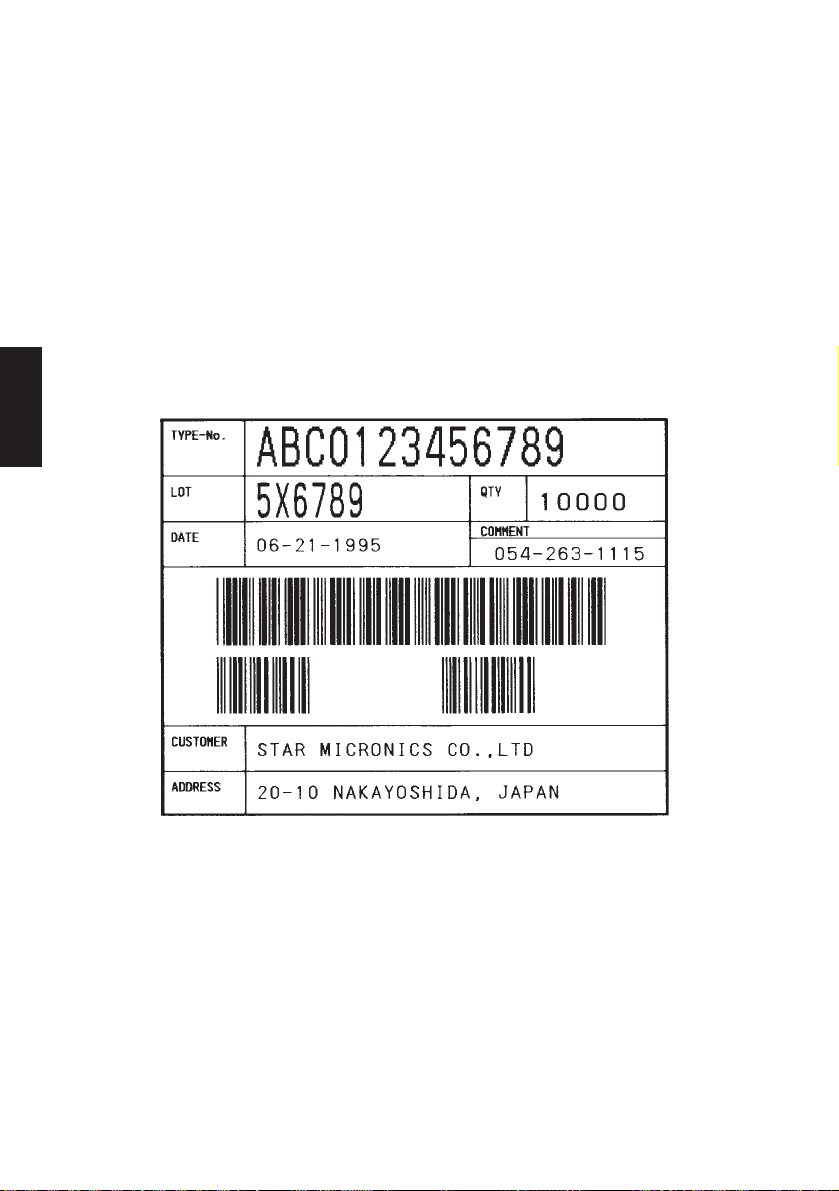
PRINT #1, E$; “RC08;COMMENT”; LN$;
PRINT #1, E$; “RC09;054-263-1115”; LN$;
PRINT #1, E$; “RC10;CUSTOMER”; LN$;
PRINT #1, E$; “RC11;STAR MICRONICS CO.,LTD”; LN$;
PRINT #1, E$; “RC12;ADDRESS”; LN$;
PRINT #1, E$; “RC13;20-10 NAKAYOSHIDA, JAPAN”; LN$;
PRINT #1, E$; “RB00;ABC0123456789”; LN$; :’Define bar code data
PRINT #1, E$; “RB01;10000”; LN$;
PRINT #1, E$; “RB02;940517”; LN$;
’——<< PRINT >>——
PRINT #1, E$; “1”; LN$; :’Print Label
END
Print Out Sample
PAGE MODE
– 59 –
Page 63

==SAMPLE PROGRAM==
’This sample program (SAMPLE2.BAS) is included in a floppy disk with the TSP400
printer.
’——<< SAMPLE2.BAS >>——
E$ = CHR$(27): LN$ = CHR$(10) + CHR$(0)
OPEN “COM1:9600,N,8,1,CS0,DS0” FOR RANDOM AS #1 :’For Serial I/F COM1:
’OPEN “COM2:9600,N,8,1,CS0,DS0” FOR RANDOM AS #1 :’For Serial I/F COM2:
’OPEN “LPT1:”FOR RANDOM AS #1: WIDTH “LPT1:”, 255 :’For Parallel I/F LPT1:
’——<< FORMAT SETTINGS >>——
PRINT #1, E$; “C”; LN$; :’Clear format
PRINT #1, E$; “D0800”; LN$; :’Set print area
PRINT #1, E$; “PC00;0300,0222,1,1,1,00,01”; LN$; :’Define character string
position and type
PRINT #1, E$; “PC01;0300,0249,1,1,1,00,01”; LN$;
PRINT #1, E$; “PC02;0300,0276,1,1,1,00,01”; LN$;
PRINT #1, E$; “PB00;0300,0330,4,1,0,0040”; LN$; :’Define bar code position
and type
PRINT #1, E$; “B”; LN$; :’Enable cutter
’——<< PRINT DATA >>——
PRINT #1, E$; “RC00;Part#”: 08210116 “;LN$; :’Set character data
PRINT #1, E$; “RC01;Name : TTL IC 74LS06 (FLAT TYPE)”; LN$;
PRINT #1, E$; “RC02;Qty.: 50 pcs “; LN$;
PRINT #1, E$; “RB00;08210116”; LN$; :’Set bar code data
’
PRINT #1, E$; “H;0135,0255,”; :’Copy BMP file to image buffer”
OPEN “TTLIC.BMP” FOR BINARY AS #2
FOR I = 1 TO LOF(2): D$ = INPUT$(1, #2): PRINT #1, D$;: NEXT l
CLOSE #2
PRINT #1, “,”; LN$
’——<< PRINT >>——
PRINT #1, E$; “I”; LN$ :’Print Label
END
Print Out Sample
PAGE MODE
– 60 –
P1995.6
Page 64

8. CONTROL CODES/LINE MODE
8-1. Line Mode Command Summary
The details of each command are shown in the following sections.
Commands to Select Characters
Control codes
<ESC> “R” n 1B 52 n Select international character set 65
<ESC> “/” “1” 1B 2F 31
<ESC> “/” <1> 1B 2F 01
<ESC> “/” “0” 1B 2F 30
<ESC> “/” <0> 1B 2F 00
<ESC> “b” n1 n2 n3 n4 1B 62 n1 n2 n3 n4 Select bar code printing 66
d1 ... <RS> d1 ... 1E
LINE MODE
<ESC> “M” 1B 4D Select 12-dot pitch printing 70
<ESC> “p” 1B 70 Select 14-dot pitch printing 70
<ESC> “P” 1B 50 Select 15-dot pitch printing 70
<ESC> “:” 1B 3A Select 16-dot pitch printing 70
<ESC> <SP> n 1B 20 n Set character spacing 70
<SO> 0E Sets the printing magnified double in 71
<DC4> 14 Resets the printing magnified in 71
<ESC> “W” n 1B 57 n
<ESC> <SO> 1B 0E Sets the printing magnified double in 71
<ESC> <DC4> 1B 14 Resets the printing magnified in character 71
<ESC> “h” n 1B 68 n
<ESC> “i” n1 n2 1B 69 n1 n2 Sets the magnification rates in character 72
<ESC> “–” “1” 1B 2D 31
<ESC> “–” <1> 1B 2D 01
<ESC>“–” “0” 1B 2D 30
<ESC> “–” <0> 1B 2D 00
<ESC> “_” “1” 1B 5F 31
<ESC> “_” <1> 1B 5F 01
<ESC> “_” “0” 1B 5F 30
<ESC> “_” <0> 1B 5F 00
Hexadecimal
codes
Function Page
Select slash zero
Select normal zero
character width.
character width.
Sets the magnification rate in character width.
character height.
height.
Sets the magnification rate in character height
width and height.
Select underlining
Cancel underlining
Select upperlining
Cancel upperlining
65
65
71
.72
72
72
73
73
– 61 –
Page 65

Control codes
<ESC> “4” 1B 34 Select highlight printing 73
<ESC> “5” 1B 35 Cancel highlight printing 73
<SI> 0F Inverted printing 73
<DC2> 12 Cancel inverted printing 73
<ESC> “E” 1B 45
<ESC> “G” 1B 47
<ESC> “F” 1B 46
<ESC> “H” 1B 48
Hexadecimal
codes
Function Page
Select emphasized printing
Cancel emphasized printing
Commands to Set the Page Format
74
74
Control codes
<ESC> “C” n 1B 43 n Set page length in lines 75
<ESC> “C” <0> n 1B 43 00 n Set page length in inches 75
<ESC> “N” n 1B 4E n Set bottom margin 75
<ESC> “O” 1B 4F Cancel bottom margin 75
<ESC> “l” n 1B 6C n Set left margin 76
<ESC> “Q” n 1B 51 n Set right margin 76
Hexadecimal
codes
Function Page
Commands to Move the Print Position
Control codes
<LF> 0A Line feed 77
<CR> 0D Carriage Return 77
<ESC> “a” n 1B 61 n Feed paper n lines 77
<FF> 0C Form feed7 77
<HT> 09 Horizontal tab 77
<VT> 0B Vertical tab 78
<ESC> “z” “1” 1B 7A 31
<ESC> “z” <1> 1B 7A 01
<ESC> “0” 1B 30 Set line spacing to 3 mm 78
<ESC> “J” n 1B 4A n One time n/4 mm feed 78
<ESC> “j” n 1B 6A n One time n/4 mm backfeed 79
<ESC>“I” n 1B 49 n One time n/8 mm feed 79
<ESC> “B” n1 n2 ... <0> 1B 42 n1 n2 ... 00 Set vertical tab stops 79
<ESC> “D” n1 n2 ... <0> 1B 44 n1 n2 ... 00 Set horizontal tab stops 80
Hexadecimal
codes
Function Page
Set line spacing to 4 mm 78
LINE MODE
– 62 –
Page 66

Commands to Print Dot Graphics
Control codes
<ESC> “K” n <0> 1B 4B n 00 m1 m2 Print normal density graphics 81
m1 m2 ... ...
<ESC> “L” n1 n2 1B 4C n1 n2 m1 m2 Print high density graphics 83
m1 m2 ... ...
<ESC> “k” n <0> d1 ... 1B 6B n 00 d1 ... Print fine density graphics 84
<ESC> “X” n1 n2 m1 •• 1B 58 n1 n2 m1 •• Print fine density graphics 87
Hexadecimal
codes
Commands to Print Download Characters
Control codes
<ESC> “&” <1> <1> 1B 26 01 01 n Define download character 88
n m1 m2 ... m48 m1 m2 ... m48
LINE MODE
<ESC> “&” <1> <0> n 1B 26 01 00 n Delete a download character7 89
<ESC> “%” “1” 1B 25 31
<ESC> “%” <1> 1B 25 01
<ESC> “%” “0” 1B 25 30
<ESC> “%” <0> 1B 25 00
Hexadecimal
codes
Commands to Control Peripheral Devices
Function Page
Function Page
Enable download character set
Disable download character set
89
89
Control codes
<ESC> <BEL> n1 n2 1B 07 n1 n2 Define drive pulse width for peripheral 90
<BEL> 07 Control peripheral device #1 90
<FS> 1C Control peripheral device #1 immediately 90
<EM> 19 Control peripheral device #2 immediately 90
<SUB> 1A Control peripheral device #2 immediately 90
Hexadecimal
codes
Function Page
device #1
Commands to Control Auto Cutter
Control codes
<ESC> “d” “0” 1B 64 30
<ESC> “d” <0> 1B 64 00
<ESC> “d” “1” 1B 64 31
<ESC> “d” <1> 1B 64 01
Hexadecimal
codes
Function Page
Full-cut command to the auto cutter 91
– 63 –
Page 67

Other Commands
Control codes
<CAN> 18 Cancel last line & Initialize printer 92
<DC3> 13 Deselect printer 93
<DC1> 11
<DC1> n 11 n
<RS> 1E Beep the buzzer 93
<ESC> “#N, n1 n2 n3 n4”
<LF> <NUL> 0A 00
<ESC> “@” 1B 40 Initialize printer 96
<ENQ> 05 Enquiry 96
<STX> 02 Enter STX-ETX mode 97
<ETX> 03 Terminate STX-ETX mode 97
<ESC> “?” <LF> <NUL> 1B 3F 0A 00 Reset printer hardware 97
Hexadecimal
codes
1B 23 N 2C n1 n2 n3 n4
Function Page
Set select mode
Set memory switch
Commands to Control Auto Cutter
Control codes
<EOT> 04 Request status 98
Hexadecimal
codes
Function Page
93
94
LINE MODE
– 64 –
Page 68

8-2. Command Specification
Commands to Select Characters
FUNCTION
CODE <ESC> “R” n
HEX
REMARKS
LINE MODE
FUNCTION
CODE <ESC> “/” n
HEX
REMARKS
Select international character set
1B 52 n
Selects an international character set according to the value of n,
as shown below:
n Character set n Character set
0 U.S.A. 7 Spain I
1 France 8 Japan
2 Germany 9 Norway
3 England 10 Denmark II
4 Denmark I 11 Spain II
5 Sweden 12 Latin America
6 Italy
When the value of n is 0 to 9, 0(00H) to 9(09H) or “0”(30H) to
“9”(39H) can be set. When the value of n is 10 to 12, 10(0AH) to
12(0CH) or “A”(41H) to “C”(43H) can be set.
Select zero style
1B 2F n
Causes subsequent zero characters to be printed with a slash when
n is 1, and without a slash when n is 0.
The value of n can be set to 0(00H) or “0”(30H), or 1(01H) or
“1”(31H).
– 65 –
Page 69

FUNCTION
CODE
HEX
REMARKS
Select bar code printing
<ESC> “b” n1 n2 n3 n4 di ... dk <RS>
1B 62 n1 n2 n3 n4 di ... dk 1E
Prints bar code according to the value of n1, as shown below:
n1: Type of bar code
1 UPC-A
2 JAN/EAN-8
3 JAN/EAN-13
4 CODE 39
5 ITF
6 CODE 128
7 CODE 93
8 NW-7
The value of n1 can be set to 1(01H) or 8(08H) or “1”(31H) to
“8”(38H).
n2: Printing character below bar code or line feed
1 Character below bar code is not printed, Line feed is
performed after execution of command.
2 Character below bar code is printed, Line feed is
performed after execution of command.
3 Character below bar code is not printed, Line feed is
not performed after execution of command.
4 Character below bar code is printed, Line feed is not
performed after execution of command.
The value of n2 can be set to 1(01H) to 4(04H) or “1”(31H) to
“4”(34H).
LINE MODE
n3: Mode of bar code
UPC-A, JAN/EAN-8, JAN/EAN-13, CODE 128, CODE 93
1 Minimum module 2 dots
2 Minimum module 3 dots
3 Minimum module 4 dots
– 66 –
Page 70

LINE MODE
CODE 39, NW-7, ITF
CODE 39, NW-7 ITF
1 Narrow : wide 2:6 dots 2:5 dots
2 Narrow : wide 3:9 dots 4:10 dots
3 Narrow : wide 4:12 dots 6:15 dots
4 Narrow : wide 2:5 dots 2:4 dots
5 Narrow : wide 3:8 dots 4:8 dots
6 Narrow : wide 4:10 dots 6:12 dots
7 Narrow : wide 2:4 dots 2:6 dots
8 Narrow : wide 3:6 dots 3:9 dots
9 Narrow : wide 4:8 dots 4:12 dots
When the value of n3 is UPC-A, JAN/EAN-8, JAN/EAN-13,
CODE128 or CODE93, 1(01H) to 3(03H) or “1”(31H) to “3”(33H)
can be set. When the value of n3 is CODE39, NW-7 or ITF, 1(01H)
to 9(09H) or “1”(31H) to “9”(39H) can be set.
n4: Height of bar code
Can be up to 255 dots (31.9mm).
If the bar code height is larger than the line feed amount, the
line feed amount is automatically multiplied by an integer.
di...dk: Bar code data
UPC-A: K = 11 (or 12)
The check digit at the 12th digit is automatically added,
and ignored even if it is specified.
JAN/EAN-8: K = 7 (or 8)
The check digit at the 8th digit is automatically added,
and ignored even if it is specified.
JAN/EAN-13: K = 12 (or 13)
The check digit at the 13th digit is automatically added,
and ignored even if it is specified.
CODE39: The value of k is optional, and the maximum
value also differs according to the modes (21
digits maximum in mode 7).
The start/stop code (“
– 67 –
”) is automatically added.
*
Page 71

ITF: The value of k is optional, and the maximum
value also differs according to the modes (40
digits maximum in mode 4).
If the data is number of an odd digits, 0 is
automatically added at the beginning of the data.
CODE 128: The value of k is optional, and the maximum
value also differs according to the modes and the
types of character number (51 digits maximum in
mode 1).
The check character is automatically added.
CODE93: The value of k is optional, and the maximum value
also differs according to the modes and the types
of character (30 digits maximum in mode 1).
The check characters (C and K) are automatically
added.
NW-7: The value of k is optional, and the maximum
value also differs according to the modes and the
types of character number (29 digits maximum in
mode 7).
The start/stop code is also contained in the data (it
is not automatically added).
LINE MODE
The bar code printing start position is at the upper end of the
current line.
If the bar code is positioned beyond the right margin, neither
the bar code nor the character below the bar code will be
printed.
Data of CODE 128 and CODE 93
When <LF> is used in a command, some kinds of control code
cannot be sent by the host PC. The control code should be sent
as the data as shown below:
• When sending the following data, express as a set of two
characters.
Express “% (25H)” as “%0 (25H30H)”.
Add “40H - 5FH” after “%” for the control codes (00H - 1FH).
Express the control code (7FH) as “%5(25H35H)”.
Add “1 - 4 (31H - 34H)” after “%” for the function code.
Add “6 - 8 (36H - 38H)” after “%” for the start code.
– 68 –
Page 72

3) 2-character codes
LINE MODE
Control codes
CODE FORMAT
NUL 00H %@ 25H 40H
SOH 01H %A 25H 41H
STX 02H %B 25H 42H
ETX 03H %C 25H 43H
EOT 04H %D 25H 44H
ENQ 05H %E 25H 45H
ACK 06H %F 25H 46H
BEL 07H %G 25H 47H
BS 08H %H 25H 48H
HT 09H %I 25H 49H
LF 0AH %J 25H 4AH
VT 0BH %K 25H 4BH
FF 0CH %L 25H 4CH
CR 0DH %M 25H 4DH
SO 0EH %N 25H 4EH
SI 0FH %O 25H 4FH
DLE 10H %P 25H 50H
DC1 11H %Q 25H 51H
DC2 12H %R 25H 52H
DC3 13H %S 25H 53H
DC4 14H %T 25H 54H
NAK 15H %U 25H 55H
SYN 16H %V 25H 56H
ETB 17H %W 25H 57H
CAN 18H %X 25H 58H
EM 19H %Y 25H 59H
SUB 1AH %Z 25H 5AH
ESC 1BH %[ 25H 5BH
FC 1CH %¥ 25H 5CH
GS 1DH %] 25H 5DH
RS 1EH %^ 25H 5EH
US 1FH %_ 25H 5FH
DEL 7FH %5 25H 35H
Special code
CODE FORMAT
% 25H %0 25H 30H
Function codes
CODE FORMAT
FNC1 %1 25H 31H
FNC2 %2 25H 32H
FNC3 %3 25H 33H
FNC4 %4 25H 34H
Start codes
CODE FORMAT
START A %6 25H 36H
START B %7 25H 37H
START C %8 25H 38H
✩ For CODE 128 only.
✩
✩
✩
✩
✩
✩
✩
– 69 –
Page 73
FUNCTION
CODE
FUNCTION
FUNCTION
FUNCTION
FUNCTION
HEX
REMARKS
CODE
HEX
REMARKS
CODE
HEX
REMARKS
CODE
HEX
REMARKS
Select 12-dot pitch printing
<ESC> “M”
1B 4D
Prints 12-dot pitch characters without an extra space.
Select 14-dot pitch printing
<ESC> “p”
1B 70
Prints 12-dot pitch characters with 2-dot spacing between characters.
Select 15-dot pitch printing
<ESC> “P”
1B 50
Prints 12-dot pitch characters with 3-dot spacing between characters.
LINE MODE
Select 16-dot pitch printing
<ESC> “:”
1B 3A
Prints 12-dot pitch characters with 4-dot spacing between characters.
CODE
HEX
REMARKS
Set the character spacing
<ESC> <SP> n
1B 20 n
Sets the space between characters to n dots, where n is a number
from 0 to 15.
When the value of n is 0 to 9, 0(00H) to 9(09H) or “0”(30H) to
“9”(39H) can be set. When the value of n is 10 to 15, 10(0AH) to
15(0FH) or “A”(41H) to “F”(46H) can be set.
– 70 –
Page 74

FUNCTION
CODE
FUNCTION
FUNCTION
FUNCTION
FUNCTION
HEX
REMARKS
CODE
HEX
REMARKS
LINE MODE
CODE
HEX
REMARKS
Sets the printing magnified double in character width.
<SO>
0E
Prints the subsequent data including a character spacing set by
<ESC><SP> n, magnified double in character width.
Resets the printing magnified in character width.
<DC4>
14
Resets the printing magnified in character width set by <SO>,
<ESC>“W”n and <ESC>“i”n1n2.
Sets the magnification rate in character width.
<ESC> “W” n
1B 57 n
Prints the subsequent data including a character spacing set by
<ESC><SP> n, magnified in character width by a rate specified by
the value of n.
n Character width n Character width
0 Unmagnify 3 Quadruple
1 Double 4 Quintuple
2 Triple 5 Sextuple
The value of n can be set to 0(00H) to 5(05H) or “0”(30H) to
“5”(35H).
CODE
HEX
REMARKS
CODE
HEX
REMARKS
Sets the printing magnified double in character height.
<ESC><SO>
1B 0E
Prints the subsequent data magnified double in character height.
Resets the printing magnified in character height.
<ESC><DC4>
1B 14
Resets the printing magnified in character height set by
<ESC><SO>, <ESC>“h”n and <ESC>“i”n1n2.
– 71 –
Page 75
FUNCTION
CODE
FUNCTION
FUNCTION
HEX
REMARKS
CODE
HEX
REMARKS
Sets the magnification rate in character height.
<ESC> “h” n
1B 68 n
Prints the subsequent data magnified in character height by a rate
specified by the value of n.
n Character height n Character height
0 Unmagnify 3 Quadruple
1 Double 4 Quintuple
2 Triple 5 Sextuple
The value of n can be set to 0(00H) to 5(05H) or “0”(30H) to
“5”(35H).
Sets the magnification rates in character width and height.
<ESC> “i” n1 n2
1B 69 n1 n2
Prints the subsequent data in the size specified by n1, n2.
n1 indicates the height magnification and n2 indicates the width
magnification.
n1 (n2) = 0 Normal height (or width) size.
1 Double height (or width) size.
2 Triple height (or width) size.
3 Quadruple height (or width) size.
4 Quintuple height (or width) size.
5 Sextuple height (or width) size.
The values of n1, n2 are 0(00H) to 5(05H) or “0”(30H)” to
“5”(35H).
LINE MODE
CODE
HEX
REMARKS
Underlining
<ESC> “–” n
1B 2D n
When the value of n is 1, underlines the subsequent data including
a character spacing set by <ESC><SP> n.
The part to be skipped by the horizontal tab setting and the block
graphic characters are not underlined.
Resets the underline mode when the value of n is 0.
The value of n can be set to 0(00H) or “0”(30H), or 1(01H) or
“1”(31H).
– 72 –
Page 76
FUNCTION
CODE
FUNCTION
FUNCTION
FUNCTION
FUNCTION
HEX
REMARKS
CODE
LINE MODE
HEX
REMARKS
CODE
HEX
REMARKS
Upperlining
<ESC> “_” n
1B 5F n
When the value of n is 1, overlines the subsequent data including
a character spacing set by <ESC><SP> n.
The part to be skipped by the horizontal tab setting and the block
graphic characters are not upperlined.
Resets the upperline mode when the value of n is 0.
The value of n can be set to 0(00H) or “0”(30H), or 1(01H) or
“1”(31H).
Select highlight printing
<ESC> “4”
1B 34
Prints the subsequent data including a character spacing set by
<ESC><SP> n reversed.
The part to be skipped by the horizontal tab setting is not reversed.
Cancel highlight printing
<ESC> “5”
1B 35
Cancels highlight printing.
CODE
HEX
REMARKS
CODE
HEX
REMARKS
Inverted printing
<SI>
0F
Causes subsequent characters to be inverted.
Cancel inverted printing
<DC2>
12
Cancels inverted printing.
– 73 –
Page 77

FUNCTION
CODE
FUNCTION
HEX
CODE
HEX
REMARKS
CODE
HEX
CODE
HEX
REMARKS
Select emphasized printing
<ESC> “E”
1B 45
<ESC> “G”
1B 47
Causes subsequent characters to be emphasized.
Cancel emphasized printing
<ESC> “F”
1B 46
<ESC> “H”
1B 48
Cancels emphasized printing.
LINE MODE
– 74 –
Page 78
Commands to Set the Page Format
FUNCTION
FUNCTION
FUNCTION
FUNCTION
Set page length in lines
CODE <ESC> “C” n
HEX
REMARKS
1B 43 n
Sets the page length using the current line spacing, where n is
between 1 and 127.
Changing the line spacing later does not alter the physical page
length.
The current line becomes the top of the page.
Resets the bottom margin.
Invalid when start position detect is ON.
Set page length in inches
LINE MODE
CODE <ESC> “C” <0> n
HEX
REMARKS
1B 43 00 n
Sets the page length to n × 24 mm, where n is between 1 and 22.
The current line becomes the top of the page.
Resets the bottom margin.
Invalid when start position detect is ON.
Set bottom margin
CODE <ESC> “N” n
HEX
REMARKS
1B 4E n
Sets the bottom margin to n lines at the current line spacing, where
n is between 0 and 127.
Bottom margin is reset when you change the page length.
Setting is invalid if the printing area on one page is 36 mm or less.
Invalid when start position detect is ON.
Cancel bottom margin
CODE <ESC> “O”
HEX
REMARKS
1B 4F
Cancels the bottom margin.
Invalid when start position detect is ON.
– 75 –
Page 79

FUNCTION
CODE
FUNCTION
HEX
REMARKS
CODE
HEX
REMARKS
Set left margin
<ESC> “l” n
1B 6C n
Sets the left margin at column n (where n is between 0 and 255) at
the current character pitch.
The left margin does not move if the character pitch is changed
later.
Setting is invalid if the printing area for one line would be 36mm
or less.
Set right margin
<ESC> “Q” n
1B 51 n
Sets the right margin at column n (where n is between 1 and 255)
at the current character pitch.
The right margin does not move if the character pitch is changed
later.
Setting is invalid if the printing area for one line would be 36mm
or less.
LINE MODE
– 76 –
Page 80

Commands to Move the Print Position
FUNCTION
FUNCTION
FUNCTION
FUNCTION
FUNCTION
Line feed
CODE <LF>
HEX
REMARKS
0A
Prints the current line and feeds the paper to the next line.
Carriage return
CODE <CR>
HEX
REMARKS
0D
Prints the current line and feeds the paper to the next line.
This command is ignored when CR code is invalid.
LINE MODE
CODE <ESC> “a” n
HEX
REMARKS
CODE <FF>
HEX
REMARKS
CODE <HT>
HEX
REMARKS
Feed paper n lines
1B 61 n
Prints the current line and feeds the paper n lines (where n is
between 1 and 127).
Form feed
0C
Feeds the paper to the top of the next page, according to the page
length set by <ESC>“C”n or <ESC>“C”<0>n when memory switch
1-8 is set to 0, and according to the sensor output when the memory
switch is set to 1. The print position is at the left margin in both cases.
Horizontal tab
09
Moves the print position to the next horizontal tab stop. Ignored if
there is no next horizontal tab stop on the current line.
– 77 –
Page 81

FUNCTION
CODE
FUNCTION
FUNCTION
FUNCTION
HEX
REMARKS
CODE
HEX
REMARKS
CODE
HEX
REMARKS
Vertical tab
<VT>
0B
When start position detect is invalid, feeds the paper to the next
vertical tab stop and moves the print position to the left margin.
Performs a line feed if no vertical tabs are set or if the current line
is at or below the last vertical tab stop.
Same as <LF> when start position detect is valid.
Set line spacing to 4 mm
<ESC> “z” “1” or <ESC> “z” <1>
1B 7A 31 or 1B 7A 01
Sets the distance the paper advances in subsequent line feeds to
4 mm.
Set line spacing to 3 mm
<ESC> “0”
1B 30
Sets the distance the paper advances in subsequent line feeds to
3 mm.
LINE MODE
CODE
HEX
REMARKS
One time n/4 mm feed
<ESC> “J” n
1B 4A n
Performs a line feed of n/4mm once only.
The value of n is 1 to 255.
Space setting for lines is not changed.
– 78 –
Page 82

FUNCTION
CODE
FUNCTION
FUNCTION
HEX
REMARKS
CODE
HEX
LINE MODE
REMARKS
CODE
HEX
REMARKS
One time n/4 mm backfeed
<ESC> “j” n
1B 6A n
Feeds the paper back n/4mm once only.
The value of n is 1 to 255.
Space setting for one line is not changed.
This command can also feed the paper back to the page before the
current page. In this case, the position of the line on the previous
page is determined by the page length control.
One time n/8 mm feed
<ESC> “I” n
1B 49 n
Performs a line feed n/8mm once only.
The value of n is 1 to 255.
Space setting for lines is not changed.
Set vertical tab stops
<ESC> “B” n1 n2 ... <0>
1B 42 n1 n2 ... 00
Cancels all current vertical tab stops and sets new vertical tab stops
at lines n1, n2, etc., where n1, n2, etc. are numbers between 0 and
255. A maximum of 16 vertical tab stops can be set.
The tab stops must be specified in ascending order; any violation
of ascending order terminates the tab stop list. Standard termination is by the <0> control code.
The vertical tab stops are set in terms of the current line spacing and
do not move if the line spacing is changed later.
Invalid when start position detect is valid.
– 79 –
Page 83

FUNCTION
CODE
HEX
REMARKS
Set horizontal tab stops
<ESC> “D” n1 n2 ... <0>
1B 44 n1 n2 ... 00
Cancels all current horizontal tab stops and sets new tab stops at
columns n1, n2, etc. at the current character pitch, where n1, n2,
etc. are numbers between 1 and 255. A maximum of 16 horizontal
tab stops can be set.
The tab stops must be specified in ascending order; any violation
of ascending order terminates the tab stop list. Standard termination is by the <0> control code.
LINE MODE
– 80 –
Page 84

Commands to Print Dot Graphics
FUNCTION
Print normal density graphics
CODE <ESC> “K” n <0> m1 m2 ...
HEX
REMARKS
1B 4B n 00 m1 m2 ...
Prints normal density dot graphics. The graphics image is 24 dots
high and n × 3 dots wide. Maximum width is 600 dots.
m1, m2, ... are the dot data, each a 1-byte value from 0 to 255
representing 24 vertical dots, with the most significant bit representing the top three and the least significant bit representing the
bottom three.
The number of data bytes must be n.
Dots beyond the right margin are ignored.
Relationship between image data and print dots
LINE MODE
DOT Position
1
1
2
3
4
5
6
7
8
9
10
11
12
13
14
15
16
17
18
19
20
21
22
23
24
23
MSB
D8
Image data LSB
D7 D6 D5 D4 D3 D2 D1
– 81 –
Page 85

EXAMPLE
We will create the design below using a bit image.
m1 m2 m3 m4 m5 m6 m7 m8 m9 m10 m11 m12 m13 m14 m15 m16 m17 m18 m19 m20 m21 m22 m23 m24 m25 m26 m27 m28 m29 m30
D8
D7
D6
D5
D4
D3
D2
D1
Printing Sample
First, since the volume of data is 30, n1 = (1E)
H. If the data m1 ~
m30 is converted to hexadecimal, it appears as shown below.
Data Binary
Hexa-
decimal
m1 00000001 01
m2 00011110 1E
m3 00111110 3E
m4 01011111 5F
m5 00011111 1F
m6 01011110 5E
m7 00011110 1E
m8 00111111 3F
m9 00101111 2F
m10 00111110 3E
Data Binary
m11 00111110 3E
m12 00000010 02
m13 00000010 02
m14 00111110 3E
m15 00111110 3E
m16 00101111 2F
m17 00101111 2F
m18 00111110 3E
m19 00101110 2E
m20 00101110 2E
Hexa-
Data Binary
decimal
m21 00111110 3E
m22 00101110 2E
m23 00101110 2E
m24 00111110 3E
m25 00101111 2F
m26 00101111 2F
m27 00111110 3E
m28 00111110 3E
m29 00000010 02
m30 00000010 02
decimal
Hexa-
LINE MODE
– 82 –
Page 86

FUNCTION
Print high density graphics
CODE
HEX
REMARKS
<ESC> “L” n1 n2 m1 m2 ...
1B 4C n1 n2 m1 m2 ...
Prints high density dot graphics. The graphics image is 24 dots
high and n1 + n2 × 256 dots wide. Maximum width is 600 dots.
m1, m2, ... are the dot data, each a 1-byte value from 0 to 255
representing 24 vertical dots, with the most significant bit representing the top three and the least significant bit representing the
bottom three.
The number of data bytes must be n1 + n2 × 256.
Dots beyond the right margin are ignored.
Relationship between image data and print dots
LINE MODE
DOT Position
1
1
2
3
4
5
6
7
8
9
10
11
12
13
14
15
16
17
18
19
20
21
22
23
24
MSB
D8
D7 D6 D5 D4 D3 D2 D1
Image data LSB
– 83 –
Page 87

EXAMPLE
FUNCTION
We will create the design below using a bit image.
m1 m2 m3 m4 m5 m6 m7 m8 m9 m10 m11 m12 m13 m14 m15 m16 m17 m18 m19 m20 m21 m22 m23 m24 m25 m26 m27 m28 m29 m30
D8
D7
D6
D5
D4
D3
D2
D1
First, since the volume of data is 30, n1 = (1E)
H. If the data m1 ~
m30 is converted to hexadecimal, it appears as shown below.
Data Binary
Hexa-
decimal
m1 00000001 01
m2 00011110 1E
m3 00111110 3E
m4 01011111 5F
m5 00011111 1F
m6 01011110 5E
m7 00011110 1E
m8 00111111 3F
m9 00101111 2F
m10 00111110 3E
Data Binary
m11 00111110 3E
m12 00000010 02
m13 00000010 02
m14 00111110 3E
m15 00111110 3E
m16 00101111 2F
m17 00101111 2F
m18 00111110 3E
m19 00101110 2E
m20 00101110 2E
Hexa-
Data Binary
decimal
m21 00111110 3E
m22 00101110 2E
m23 00101110 2E
m24 00111110 3E
m25 00101111 2F
m26 00101111 2F
m27 00111110 3E
m28 00111110 3E
m29 00000010 02
m30 00000010 02
decimal
Hexa-
LINE MODE
Printing Sample
CODE
HEX
REMARKS
Horizontal density is three times that of the bit image for <ESC>“k”.
(Compare the print samples.)
Print fine density bit image
<ESC> “k” n <0> d1...dk [k = n * 24]
1B 6B n 00 d1...dk [k = n * 24]
Prints a bit image using 1 horizontal dot and 1 vertical dot for 1 dot
of input data.
n is designated by the number of data bytes in the horizontal
direction and n must be within the range 1 to 80.
The data is ignored if it is longer than 80 digits or goes beyond the
right margin. Relationship between the input data and actual
printing is shown below.
– 84 –
Page 88

Relationship between image data and print dots
Dot position
d1
dn+1
d2n+1
d3n+1
d4n+1
d5n+1
d6n+1
d7n+1
d8n+1
d9n+1
d10n+1
d11n+1
d12n+1
d13n+1
d14n+1
d15n+1
d16n+1
d17n+1
d18n+1
d19n+1
d20n+1
d21n+1
d22n+1
d23n+1
LINE MODE
b7 b6 b5 b4 b3 b2 b1 b0
b7 b6 b5 b4 b3 b2 b1 b0
b7 b6 b5 b4 b3 b2 b1 b0
b7 b6 b5 b4 b3 b2 b1 b0
b7 b6 b5 b4 b3 b2 b1 b0
b7 b6 b5 b4 b3 b2 b1 b0
b7 b6 b5 b4 b3 b2 b1 b0
b7 b6 b5 b4 b3 b2 b1 b0
b7 b6 b5 b4 b3 b2 b1 b0
b7 b6 b5 b4 b3 b2 b1 b0
b7 b6 b5 b4 b3 b2 b1 b0
b7 b6 b5 b4 b3 b2 b1 b0
b7 b6 b5 b4 b3 b2 b1 b0
b7 b6 b5 b4 b3 b2 b1 b0
b7 b6 b5 b4 b3 b2 b1 b0
b7 b6 b5 b4 b3 b2 b1 b0
b7 b6 b5 b4 b3 b2 b1 b0
b7 b6 b5 b4 b3 b2 b1 b0
b7 b6 b5 b4 b3 b2 b1 b0
b7 b6 b5 b4 b3 b2 b1 b0
b7 b6 b5 b4 b3 b2 b1 b0
b7 b6 b5 b4 b3 b2 b1 b0
b7 b6 b5 b4 b3 b2 b1 b0
b7 b6 b5 b4 b3 b2 b1 b0
b7 b6 b5 b4 b3 b2 b1 b0
d2
dn+2
b7 b6 b5 b4 b3 b2 b1 b0
d2n+2
b7 b6 b5 b4 b3 b2 b1 b0
d3n+2
b7 b6 b5 b4 b3 b2 b1 b0
d4n+2
b7 b6 b5 b4 b3 b2 b1 b0
d5n+2
b7 b6 b5 b4 b3 b2 b1 b0
d6n+2
b7 b6 b5 b4 b3 b2 b1 b0
d7n+2
b7 b6 b5 b4 b3 b2 b1 b0
d8n+2
b7 b6 b5 b4 b3 b2 b1 b0
d9n+2
b7 b6 b5 b4 b3 b2 b1 b0
d10n+2
b7 b6 b5 b4 b3 b2 b1 b0
d11n+2
b7 b6 b5 b4 b3 b2 b1 b0
d12n+2
b7 b6 b5 b4 b3 b2 b1 b0
d13n+2
b7 b6 b5 b4 b3 b2 b1 b0
d14n+2
b7 b6 b5 b4 b3 b2 b1 b0
d15n+2
b7 b6 b5 b4 b3 b2 b1 b0
d16n+2
b7 b6 b5 b4 b3 b2 b1 b0
d17n+2
b7 b6 b5 b4 b3 b2 b1 b0
d18n+2
b7 b6 b5 b4 b3 b2 b1 b0
d19n+2
b7 b6 b5 b4 b3 b2 b1 b0
d20n+2
b7 b6 b5 b4 b3 b2 b1 b0
d21n+2
b7 b6 b5 b4 b3 b2 b1 b0
d22n+2
b7 b6 b5 b4 b3 b2 b1 b0
d23n+2
b7 b6 b5 b4 b3 b2 b1 b0
Image data
b7 b6 b5 b4 b3 b2 b1 b0
•••
•••
•••
•••
•••
•••
•••
•••
•••
•••
•••
•••
•••
•••
•••
•••
•••
•••
•••
•••
•••
•••
•••
•••
b7 b6 b5 b4 b3 b2 b1 b0
b7 b6 b5 b4 b3 b2 b1 b0
b7 b6 b5 b4 b3 b2 b1 b0
b7 b6 b5 b4 b3 b2 b1 b0
b7 b6 b5 b4 b3 b2 b1 b0
b7 b6 b5 b4 b3 b2 b1 b0
b7 b6 b5 b4 b3 b2 b1 b0
b7 b6 b5 b4 b3 b2 b1 b0
b7 b6 b5 b4 b3 b2 b1 b0
b7 b6 b5 b4 b3 b2 b1 b0
b7 b6 b5 b4 b3 b2 b1 b0
b7 b6 b5 b4 b3 b2 b1 b0
b7 b6 b5 b4 b3 b2 b1 b0
b7 b6 b5 b4 b3 b2 b1 b0
b7 b6 b5 b4 b3 b2 b1 b0
b7 b6 b5 b4 b3 b2 b1 b0
b7 b6 b5 b4 b3 b2 b1 b0
b7 b6 b5 b4 b3 b2 b1 b0
b7 b6 b5 b4 b3 b2 b1 b0
b7 b6 b5 b4 b3 b2 b1 b0
b7 b6 b5 b4 b3 b2 b1 b0
b7 b6 b5 b4 b3 b2 b1 b0
b7 b6 b5 b4 b3 b2 b1 b0
b7 b6 b5 b4 b3 b2 b1 b0
dn
d2n
d3n
d4n
d5n
d6n
d7n
d8n
d9n
d10n
d11n
d12n
d13n
d14n
d15n
d16n
d17n
d18n
d19n
d20n
d21n
d22n
d23n
d24n
– 85 –
Page 89

EXAMPLE
MSB LSB MSB LSB
d1
d3
d5
d7
d9
d11
d13
d15
d17
d19
d21
d23
d25
d27
d29
d31
d33
d35
d37
d39
d41
d43
d45
d47
Printing Sample
d2
d4
d6
d8
d10
d12
d14
d16
d18
d20
d22
d24
d26
d28
d30
d32
d34
d36
d38
d40
d42
d44
d46
d48
BinaryData
Hexa-
decimal
d1 00000000 00
d3 00011111 1F
d5 00111111 3F
d7 01110111 77
d9 11111000 F8
d11 11111000 F8
d13 11111000 F8
d15 00001111 0F
d17 00011111 1F
d19 00011111 1F
d21 00111110 3E
d23 00111000 38
d25 011111001 79
d27 01110011 73
d29 01110011 73
d31 11111001 F9
d33 11111000 F8
d35 11111110 FE
d37 11111111 FF
d39 11111111 FF
d41 00000000 00
d43 00000000 00
d45 00000000 00
d47 00000000 00
BinaryData
Hexa-
decimal
d2 00000000 00
d4 11111000 F8
d6 11111100 FC
d8 01110111 EE
d10 00011111 1F
d12 00011111 1F
d14 00011111 1F
d16 11110000 F0
d18 11111000 F8
d20 11111000 F8
d22 01111100 7C
d24 00011100 1C
d26 10011110 9E
d28 11001110 CE
d30 11001110 CE
d32 10011111 9F
d34 00011111 1F
d36 01111111 7F
d38 11111111 FF
d40 11111111 FF
d42 00000000 00
d44 00000000 00
d46 00000000 00
d48 00000000 00
– 86 –
LINE MODE
Page 90

FUNCTION
CODE
HEX
REMARKS
Print fine density graphics
<ESC> “X” n1 n2 d1...d [(n1+n2*256)*3]
1B 5 n1 n2 d1...d [(n1+n2*256)*3]
Prints a bit image of the input data using horizontal and vertical
resolutions of 8 dots/mm.
Data extending past the right margin is ignored.
The relationship between the input data and the actual printing is
shown below.
n1 + n2 × 256 600
1
Dot
Position
1
2
3
LINE MODE
4
5
6
7
8
9
10
11
12
13
14
15
16
17
18
19
20
21
22
23
24
MSB
b7 b6 b5 b4 b3 b2 b1 b0
d1•••
LSB
MSB LSB
b7 b6 b5 b4 b3 b2 b1 b0
d2•••
MSB LSB
b7 b6 b5 b4 b3 b2 b1 b0
d3•••
– 87 –
Page 91

Commands to Print Download Characters
FUNCTION
Define download character
CODE <ESC> “&” <1> <1> nm1m2... m48
HEX
REMARKS
1B 26 01 01 nm1m2... m48
Defines one new character and stores it in RAM for later use.
n is the character code of the character defined and must be
between 32 and 127.
The character matrix is 12 dots wide and 24 dots high.
Relationship between the character pattern and the character data
is shown below.
EXAMPLE
MSB LSB MSB LSB
m1
m3
m5
m7
m9
m11
m13
m15
m17
m19
m21
m23
m25
m27
m29
m31
m33
m35
m37
m39
m41
m43
m45
m47
m2
m4
m6
m8
m10
m12
m14
m16
m18
m20
m22
m24
m26
m28
m30
m32
m34
m36
m38
m40
m42
m44
m46
m48
LINE MODE
Ignored
4 bits
– 88 –
Page 92

LINE MODE
BinaryData
m1 00011000 18
m3 00111000 38
m5 01111000 78
m7 00011000 18
m9 00011000 18
m11 00011000 18
m13 00011000 18
m15 00011001 19
m17 00011011 1B
m19 00000110 06
m21 00001100 0C
m23 00011011 1B
m25 00110111 37
m27 01100110 66
m29 00000000 00
m31 00000000 00
m33 00000001 01
m35 00000011 03
m37 00000111 07
m39 00000111 07
m41 00000000 00
m43 00000000 00
m45 00000000 00
m47 00000000 00
Hexa-
decimal
BinaryData
m2 00000000 00
m4 00000000 00
m6 00000000 00
m8 00000000 00
m10 00000000 00
m12 01100000 60
m14 11000000 C0
m16 10000000 80
m18 00000000 00
m20 00000000 00
m22 00000000 00
m24 11000000 C0
m26 11100000 E0
m28 01100000 60
m30 01100000 60
m32 11000000 C0
m34 10000000 80
m36 00000000 00
m38 11100000 E0
m40 11100000 E0
m42 00000000 00
m44 00000000 00
m46 00000000 00
m48 00000000 00
Hexa-
decimal
FUNCTION
Delete a download character
CODE <ESC> “&” <1> <0> n
HEX
REMARKS
FUNCTION
1B 26 01 00 n
Deletes the download character which was assigned the value n.
Enable download character set
CODE <ESC> “%” “1” or <ESC> “%” <1>
HEX
REMARKS
FUNCTION
1B 25 31 or 1B 25 01
Enables the download character set.
Disable download character set
CODE <ESC> “%” “0” or <ESC> “%” <0>
HEX
REMARKS
1B 25 30 or 1B 25 00
Disables the selected download character set and returns to the
built-in ROM character set.
– 89 –
Page 93

Commands to Control Peripheral Devices
FUNCTION
CODE <ESC><BEL> n1 n2
HEX
REMARKS
Define drive pulse width for peripheral device #1
1B 07 n1 n2
Defines the drive pulse width for peripheral devices requiring
other than standard 200 ms pulse time and delay time.
n1 indicates the energizing time and n2 indicates the delay time,
using 10ms units.
FUNCTION
CODE <BEL>
HEX
REMARKS
FUNCTION
CODE <FS>
HEX
REMARKS
FUNCTION
CODE <EM>
HEX
REMARKS
Control peripheral device #1
07
Executes drive pulse for peripheral device #1.
Control peripheral device #1 immediately
1C
Executes drive pulse for peripheral device #1 immediately.
Control peripheral device #2 immediately
19
Drives peripheral device #2. The drive pulse width and delay time
are fixed at 200 ms.
LINE MODE
FUNCTION
CODE <SUB>
HEX
REMARKS
Control peripheral device #2 immediately
1A
Drives peripheral device #2. The drive pulse width and delay time
are fixed at 200 ms.
– 90 –
Page 94

Commands to Control Auto Cutter
FUNCTION
CODE <ESC> “d” “0” or <ESC> “d” <0>
HEX
CODE <ESC> “d” “1” or <ESC> “d” <1>
HEX
REMARKS
LINE MODE
Full-cut command to the auto cutter
1B 64 30 or 1B 64 00
1B 64 31 or 1B 64 01
Cuts the paper fully when start position detect is invalid.
Feeds the paper to the top of the next page, then cuts it fully when
start position detect is valid.
When auto cutter is in valid, this command is not valid.
– 91 –
Page 95

Other Commands
FUNCTION
FUNCTION
Cancel last line & Initialize printer
CODE <CAN>
HEX
REMARKS
18
Clears the line buffer, and initializes the commands set already.
Does not affect the select/de-select state in addressable mode and
DC1/DC3 mode or the external equipment drive conditions set by
the code <ESC> <BEL> n1 n2. (This is the same during a
mechanical error.)
The data cleared by the CAN code in STX-ETX mode are the data
between STX and ETX and the line buffer data, for which the
command is not initialized.
(Line buffer means the print data expansion area.)
Deselect printer
CODE <DC3>
HEX
REMARKS
13
Deselects the printer. The printer disregards all subsequent characters and commands except <DC1>, which activates the printer.
LINE MODE
– 92 –
Page 96

FUNCTION
CODE
FUNCTION
HEX
CODE
HEX
REMARKS
LINE MODE
Set select mode
When using serial interface printer;
<DC1> or <DC1> n
(11)H or (11)H n
When using parallel interface printer
<DC1>
(11)H
(1) When using serial interface printer;
This function differs depending on the setting of the DIP
switch 4.
a) When the DC1, DC3 invalid mode is set (DIP switches 2-
1 to 2-4 are all set to ON), the printer ignores this code.
b) In the DC1, DC3 valid mode (with DIP switches 4-1 to 4-
4 set to OFF), when the printer receives a <DC1> code, the
deselect mode is canceled and data following this code is
input to the buffer.
c) If the printer receives a <DC1>n code (n is the DIP switch
controlled address) during the addressable mode (with DIP
switches 2-1 to 2-4 set other than settings a) and b) above,),
the deselect mode is canceled and data following this code
is input to the buffer.
Note that addressable mode is valid only when optional RS422A interface is installed.
(2) When using parallel interface printer;
When the printer receives a <DC1> code, the deselect mode is
canceled and data following this code is input to the buffer.
CODE
HEX
REMARKS
Beep the buzzer
<RS>
1E
Sounds a brief beep tone.
– 93 –
Page 97

FUNCTION
CODE
HEX
REMARKS
Set memory switch
<ESC> “# N , n1n2n3n4” <LF> <NUL>
1B 23 N 2C n1n2n3n4 0A 00
Set the memory switch. In order to enable changed memory switch
setting, turn the printer OFF and ON again or send printer reset
command (<ESC> “?”) to the printer. Changed memory switch
settings are stored in EEPROM and these setting will be stored as
long as the time when they are changed again.
N :Memory switch number (1 or 2)
n1n2n3n4 :Mode settings (For details see below)
1)Use N=1 to set printer conditions. Parameters are follows.
n1 :Sensor select
n2 :Start-position detect
n3 :Zero style
n4 :International character set
(Default)
Parammeter
n1
n2
n3
n4
Sensor select
Start-position delect
Zero style
International character set
Setting
0
Reflective sensor
(Black mark)
OFF
Normal zero
1
Transmissive sensor
ON
Slashed zero
See below
LINE MODE
n4 Country
0 USA
1 France
2 Germany
n4 Country
C Latin America
n4 Country
3UK
4 Denmark #1
5 Sweden
n4 Country
6 Itary
7 Spain #1
8 Japan
n4 Country
9 Norway
A Denmark #2
B Spain #2
2) Use N=2 to set option-related settings. Parameters are as follows.
n1 :Always “0” (TSP400)
n2 :Cutter installed status
n3 :Always “0”
n4 :Printing speed
n Setting 0 1
n2 Cutter Invalid (TSP412) Valid (TSP442)
n4 Printing speed 50 mm/sec (Default) 25 mm/sec
– 94 –
Page 98

3)Use N=3 for folloing settings
n1 :Always “0”
n2 :Character table
n3 :Print column
n4 :Line feed, CR code
n Setting 0 1 2 3
n2 Character table Normal IBM Katakana IBM
n3 Print colum 40 50 – –
n4 Line feed (mm) 4 3 4 3
CR code Invalid Invalid Valid Valid
EXAMPLE 1
LPRINT CHR$(&H1B);“#1,010A”;CHR$(&H0A); CHR$(&H00);
LPRINT CHR$(&H1B);“#2,0100”;CHR$(&H0A); CHR$(&H00);
LINE MODE
LPRINT CHR$(&H1B);“?”;CHR$(&H0A); CHR$(&H00);
Sensor: Reflective sensor
Start position detect: ON
Zero style: Normal Zero
International character set: Denmark #2
Cutter: Valid
Printing speed: 50 mm/sec
EXAMPLE 2
LPRINT CHR$(&H1B);“#1,1111”;CHR$(&H0A); CHR$(&H00);
LPRINT CHR$(&H1B);“?”;CHR$(&H0A); CHR$(&H00);
Sensor: Transmissive sensor
Start position detect: ON
Zero style: Slashed zero
International character set: France
– 95 –
Page 99

EXAMPLE 3
FUNCTION
FUNCTION
LPRINT CHR$(&H1B);“#2,0001”;CHR$(&H0A); CHR$(&H00);
LPRINT CHR$(&H1B);“?”;CHR$(&H0A); CHR$(&H00);
Cutter: Invalid
Printing speed: 25 mm/sec
Note: In order to enable the changed memory switch setting, turn the printer OFF
and ON again or send the printer reset command (<ESC>“?”) to the printer.
Initialize printer
CODE
HEX
REMARKS
<ESC> “@”
1B 40
Reinitializes the printer. Clears the print buffer and returns settings
to their power-up values.
Does not clear the input buffer, downloaded characters, or conditions for peripheral devices.
CODE
HEX
REMARKS
Enquiry
<ENQ>
05
Causes the printer to transmit a status byte (except in STX-ETX
mode).
When this command is received after text data in STX-ETX mode,
the printer transmits the status and check bytes.
– 96 –
LINE MODE
Page 100
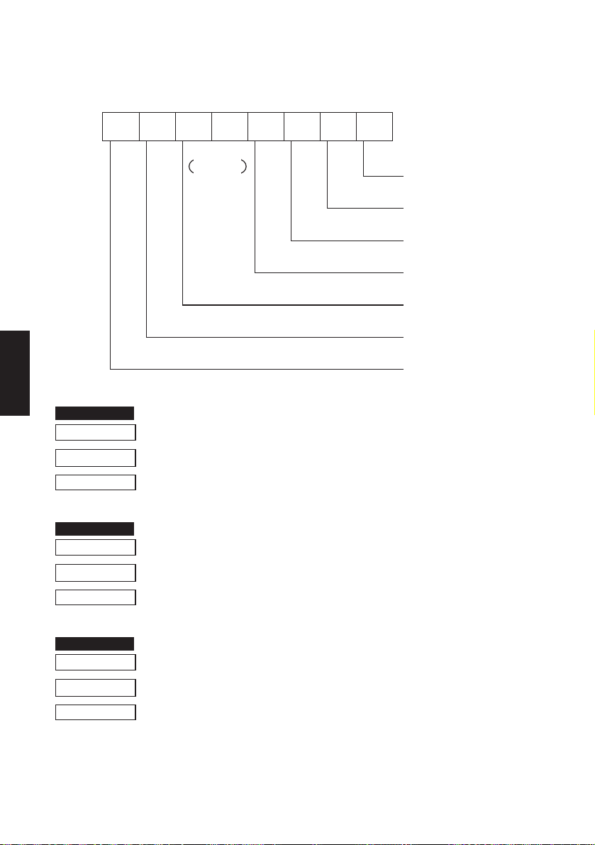
Status byte
FUNCTION
FUNCTION
FUNCTION
LINE MODE
CODE <STX>
HEX
REMARKS
b7 b6 b5 b4 b3 b2 b1 b0
0
Constantly
set at “0” Vertical Parity error
Enter STX-ETX mode
02
Causes the printer to select STX-ETX mode.
1 : error
Framing error
1 : error
Mechanical error
1 : error
Paper empty
1 : empty
Buffer empty
1 : empty
Buffer overflow
1 : overflow
Compulsion switch
High level
(Switch is set to ON)
Terminate STX-ETX mode
CODE <ETX>
HEX
REMARKS
03
Terminates STX-ETX mode, and prints out the text data.
Reset the printer hardware.
CODE <ESC> “?” <LF><NUL>
HEX
REMARKS
1B 3F 0A 00
Resets the printer hardware.
– 97 –
 Loading...