

Page 1

THERMAL PRINTER
TSP200-24
USERS MANUAL
MODE D’EMPLOI
BEDIENUNGSANLEITUNG
MANUALE DI ISTRUZIONI
Page 2

Federal Communications Commission
Radio Frequency Interference
Statement
This equipment has been tested and found to comply with the limits for a Class A digital
device, pursuant to Part 15 of the FCC Rules. These limits are designed to provide
reasonable protection against harmful interference when the equipment is operated in a
commercial environment. This equipment generates, uses and can radiate radio frequency
energy and, if not installed and used in accordance with the instruction manual, may cause
harmful interference to radio communications. Operation of this equipment in a residential
area is likely to cause harmful interference in which case the user will be required to corect
the interference at his own expense.
For compliance with the Federal Noise Interference Standard, this equipment requires a shielded
cable.
This statement will be applied only for the printers marketed in U.S.A.
Statement of
The Canadian Department of Communications
Radio Interference Regulations
This digital apparatus does not exceed the Class A limits for radio noise emissions from
digital apparatus set out in the Radio Interference Regulations of the Canadian Department
of Communications.
Le présent appareil numérique n’émet pas de bruits radioélectiques dépassant les limites
applicables aux appareils numériques de la classe A prescrites dans le Règlement sur le brouillage
radioélectrique édicté par le ministère des Communications du Canada.
The above statement applies only to printers marketed in Canada.
CE
Manufacturer’s Declaration of Conformity
EC Council Directive 89/336/EEC of 3 May 1989
This product, has been designed and manufactured in accordance with the International Standards EN 50081-1/01.92 and
EN 50082-1/01.92, following the provisions of the Electro Magnetic Compatibility Directive of the European Communities as of May 1989.
EC Council Directive 73/23/EEC and 93/68/EEC of 22 July 1993
This product, has been designed and manufactured in accordance with the International Standards EN 60950, following
the provisions of the Low Voltage Directive of the European Communities as of July 1993.
The above statement applies only to printers marketed in EU.
Trademark acknowledgments
TSP200-24: Star Micronics Co. Ltd.
ESC/POS: Seiko Epson Corporation
Notice
• All rights reserved. Reproduction of any part of this manual in any form whatsoever, without STAR’s express
permission, is strictly forbidden.
• The contents of this manual are subject to change without notice.
• All efforts have been made to ensure the accuracy of the contents of this manual at the time of printing. However,
should any errors be found, STAR would greatly appreciate being informed of them.
• The above notwithstanding, STAR can assume no responsibility for any errors in this manual.
© Copyright 1999 Star Micronics Co., Ltd.
Page 3

Table of Contents
1. Unpacking and Inspection .....................................................................1
1-1. Unpacking ....................................................................................1
1-2. Locating the Printer......................................................................1
2. Parts Identification and Nomenclature ..................................................2
3. Printer Connection.................................................................................3
3-1. Interface Cable .............................................................................3
3-2. Ferrite Core (
3-3. Optional AC Adapter ...................................................................7
4. Near-End Sensor....................................................................................8
5. Loading Paper........................................................................................9
5-1. Loading Paper ..............................................................................9
5-2. Refilling the Paper Supply .........................................................13
5-3. 76mm Width Support.................................................................14
5-4. Clearing Paper Jams...................................................................16
6. Control Panel .......................................................................................17
6-1. Power ON...................................................................................17
6-2. Combined Control Panel Operations .........................................18
6-3. Errors..........................................................................................20
6-4. Buzzer Indicators (Star Mode Only) .......................................... 21
7. Cautions ............................................................................................... 22
7-1. Operating Cautions ....................................................................22
7-2. Safety Cautions ..........................................................................22
Europe only)...............................................................5
ENGLISH
8. Command summary.............................................................................23
8-1. Star Mode................................................................................... 23
8-2. ESC/POS Mode..........................................................................27
Appendix ............................................................................................... 119
Appendix A: General Specifications ............................................... 119
Appendix B: DIP Switch Setting.....................................................123
Appendix C: Interface .....................................................................125
Appendix D: Peripheral Unit Drive Circuit ....................................130
Appendix E: Cleaning .....................................................................132
Page 4

Page 5
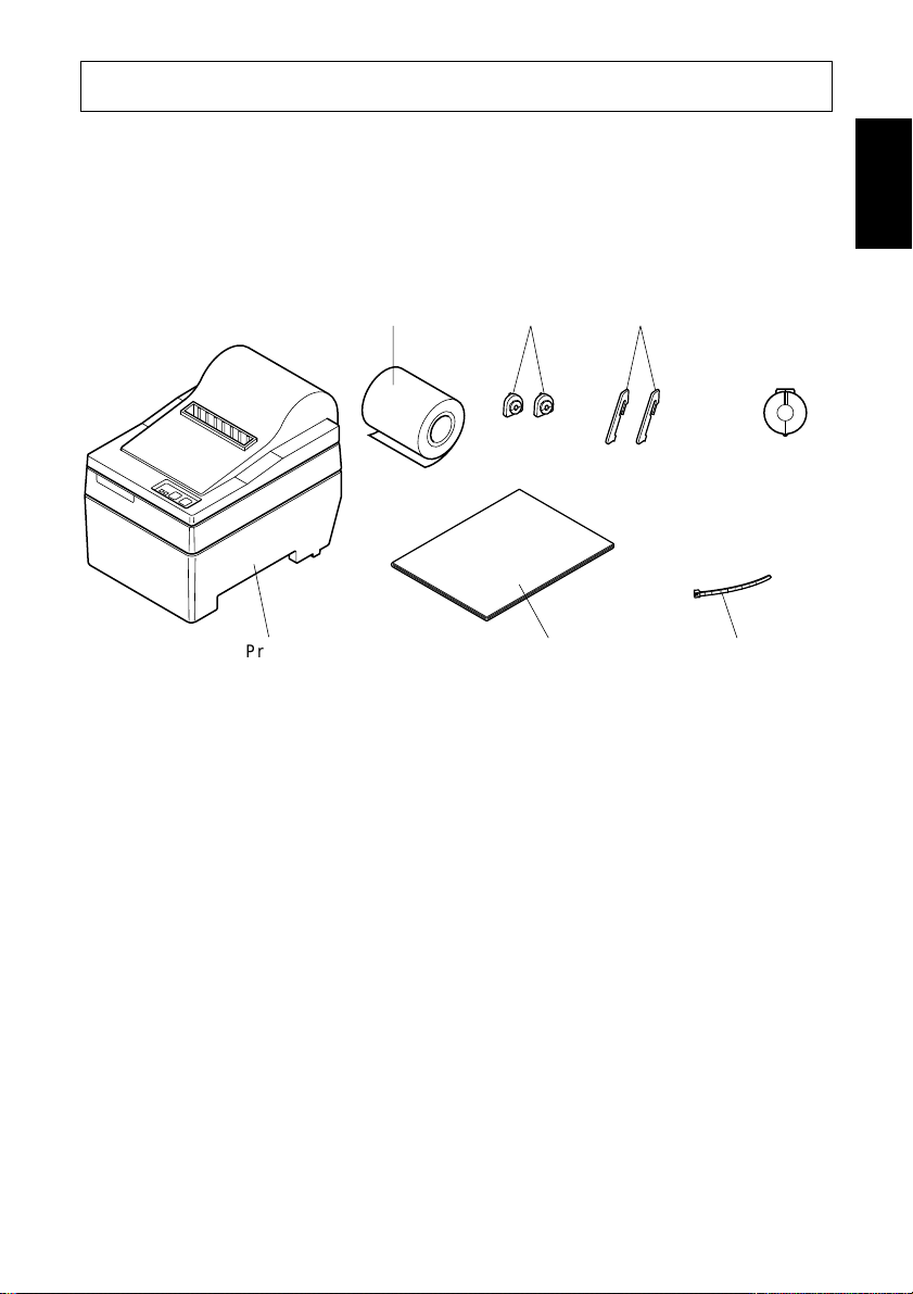
1. Unpacking and Inspection
1-1. Unpacking
Check each item in the box against Figure 1-1 to make sure that you have
everything.
If any of these items are missing, contact your supplier.
ENGLISH
Printer
Sample paper roll
Fig. 1-1
76mm holders
User's manual
support spacers
Ferrite core
for peripheral
unit cable
(E.U. only)
Fastener
(E.U. only)
1-2. Locating the printer
Before you start setting up your printer, make sure that you have a suitable place
in which to locate it. By “a suitable place”, we mean:
• Close to an easily accessible socket-outlet.
• A firm, level surface which is fairly vibration-free
• Away from excessive heat (such as direct sunlight, heaters, etc)
• Away from excessive humidity
• Away from excessive dust
• With access to a steady power supply that is not subject to power surges. For
example, do not connect the printer to the same circuit as a large, noiseproducing appliance such as a refrigerator or an air conditioner.
NOTE:Make sure that the line voltage is the voltage specified on the printer’s
identification plate.
– 1 –
Page 6
ENGLISH
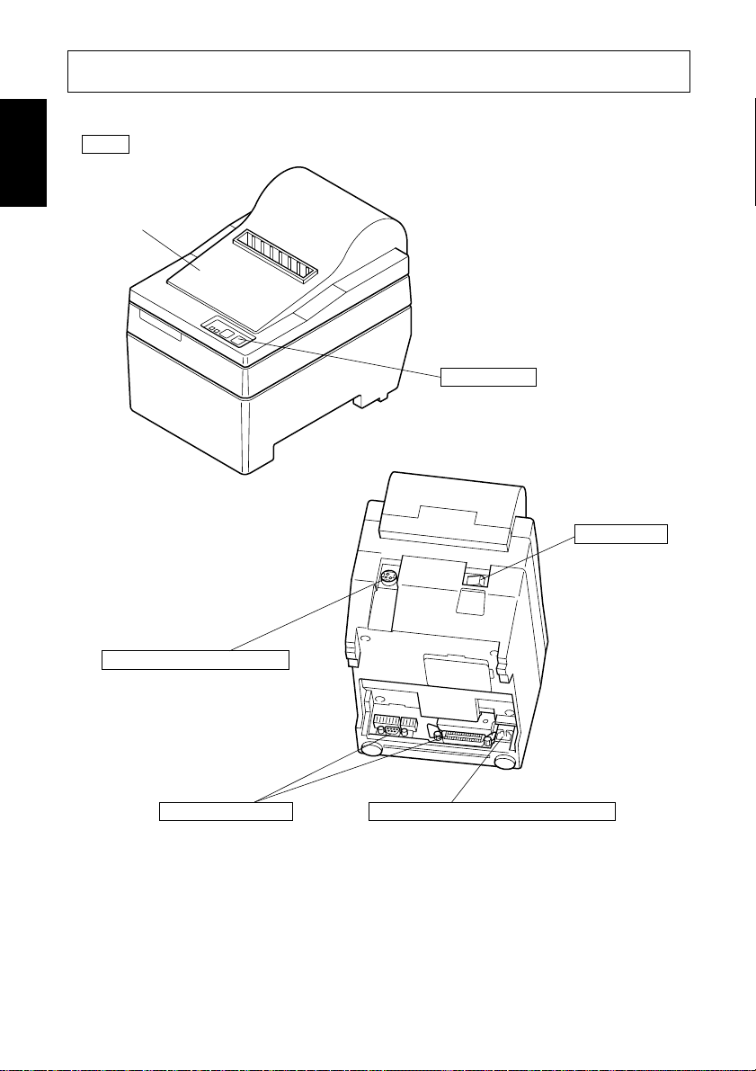
Protects the printer from
dust and reduces noise.
Do not open the cover
while printing.
2. Parts Identification and Nomenclature
Cover
Control panel
Features two control
switches and two
indicators to indicate
printer status.
Power switch
Turns printer
power on and off.
AC adapter cable connector
For connection of the AC adapter.
Never unplug the AC adapter
while the printer is on.
Interface connector
Connects the printer
with host computer.
Fig. 2-1 External view of the printer
Peripheral unit drive circuit connector
Connects to peripheral units such
as cash drawers, etc.
Do not connect this to a telephone.
– 2 –
Page 7
3. Printer Connection
Please prepare the following before making connections to the printer. Always
have the power switch in the off position when making any connections.
• Interface cable
• Ferrite core (E.U. only)
• Optional AC adapter
ENGLISH
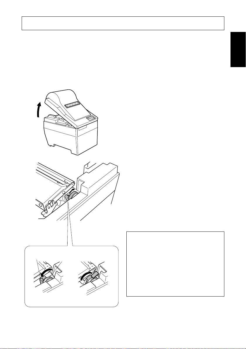
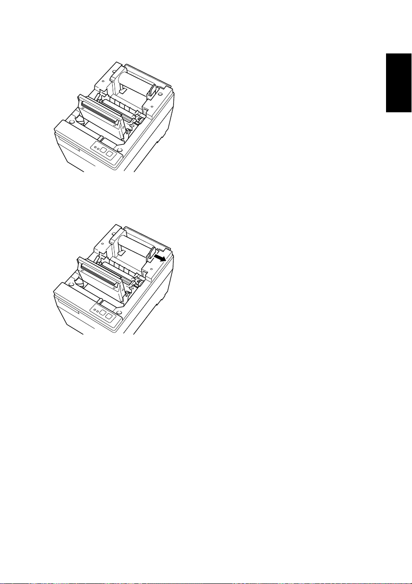
3-1. Interface Cable
Head-up
lever
[Head-up position]
Feed knob
[Head-closed position]
1 Open the cover
2 Push the head up lever (green) to the
rear.
Caution
If the printer is to be shipped, or if it
is to be stored for an extended period
of time, always pull the head up lever
forward so that the printer head is in
the up position. This will protect the
thermal head and prevent deformation of the platen.
3 Close the cover.
– 3 –
Page 8
ENGLISH
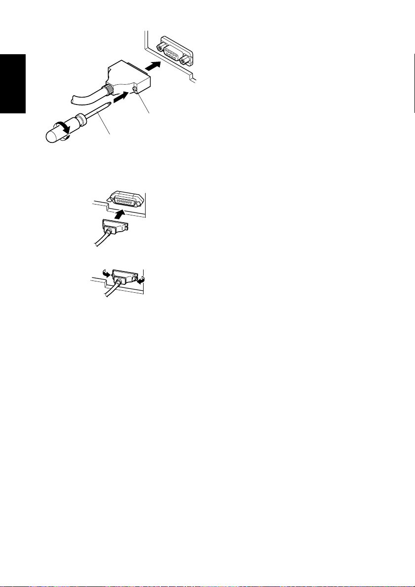
4 Plug the printer-side connector of
the interface cable into the printer
interface connector and use screws
to secure the serial interface connector or a hook bracket to secure
the parallel interface connector.
Screws
Screwdriver
– 4 –
Page 9
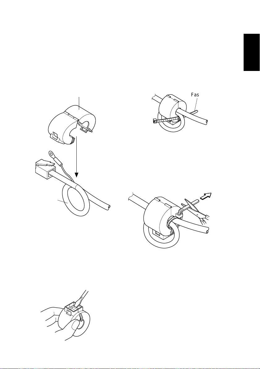
3-2. Ferrite Core (Europe only)
Fastener
NOTE:Take special care when following the procedures listed below.
■ A ferrite core noise filter for the
peripheral unit cable comes packed
with the printer.
■ The ferrite core is normally packed
so it is opened, as shown in Fig. 3-1.
Ferrite core (28mm diameter)
• Pass the fastener through the ferrite
core.
Fig. 3-3
ENGLISH
One loop
Fig. 3-1
If you find that the ferrite core is not
opened: Use a pointed object to pry
the plastic lock of the ferrite core
apart, as shown in Fig. 3-2. When
opening it, take care not to damage
the ferrite core or the plastic lock.
Fig. 3-2
Pull and cut
• Pass the fastener around the cable
and lock it.
Cut off the excess with a pair of scissors.
Fig. 3-4
– 5 –
Page 10
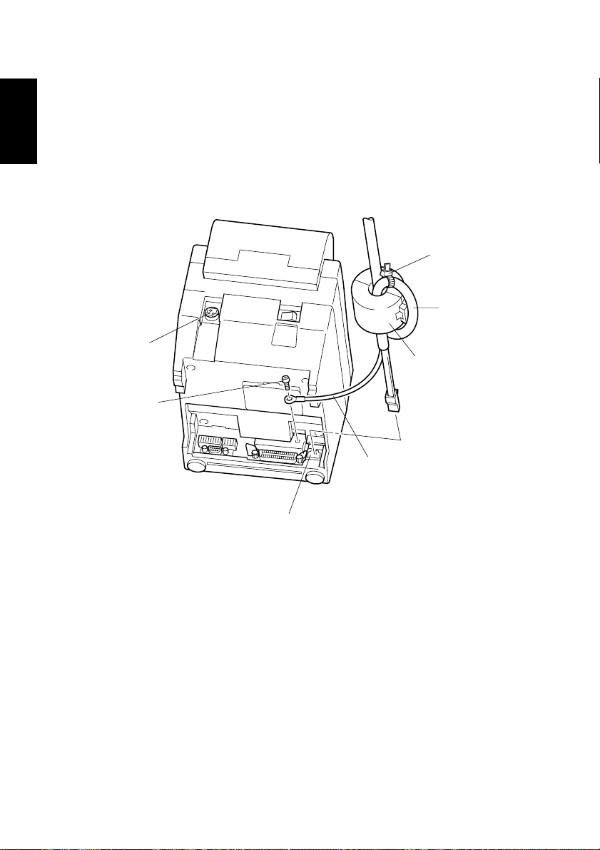
■ Clamp the ferrite core onto the peripheral unit cable, looping the cable as
shown in Fig. 3-1.
ENGLISH
• When installing the ferrite core be careful not to damage the cable.
• The ferrite core should be anchored firmly in place with the fastener that
comes with it, as shown in Fig. 3-3 and Fig. 3-4.
• Do not forget to loop the cable.
Fastener
One loop
Connector
Ferrite core
Screw M3×4
Peripheral unit drive
circuit connector
Fig. 3-5
– 6 –
Separate ground wire
Page 11
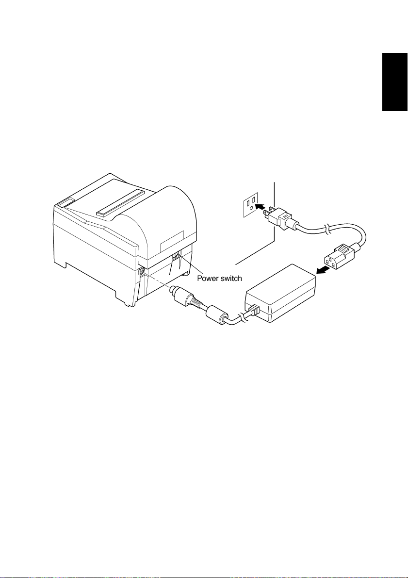
3-3. Optional AC Adapter
NOTE:Before connecting/disconnecting the AC adapter, make sure that power
to the printer and all the devices connected to the printer is turned off.
Also make sure the power cable plug is disconnected from the AC outlet.
1 Connect the AC adapter to the power cable.
Note: Use only the standard AC adapter and power cable.
2 Connect the AC adapter to the connector on the printer.
3 Insert the power cable plug into an AC outlet.
Fig. 3-6
ENGLISH
– 7 –
Page 12
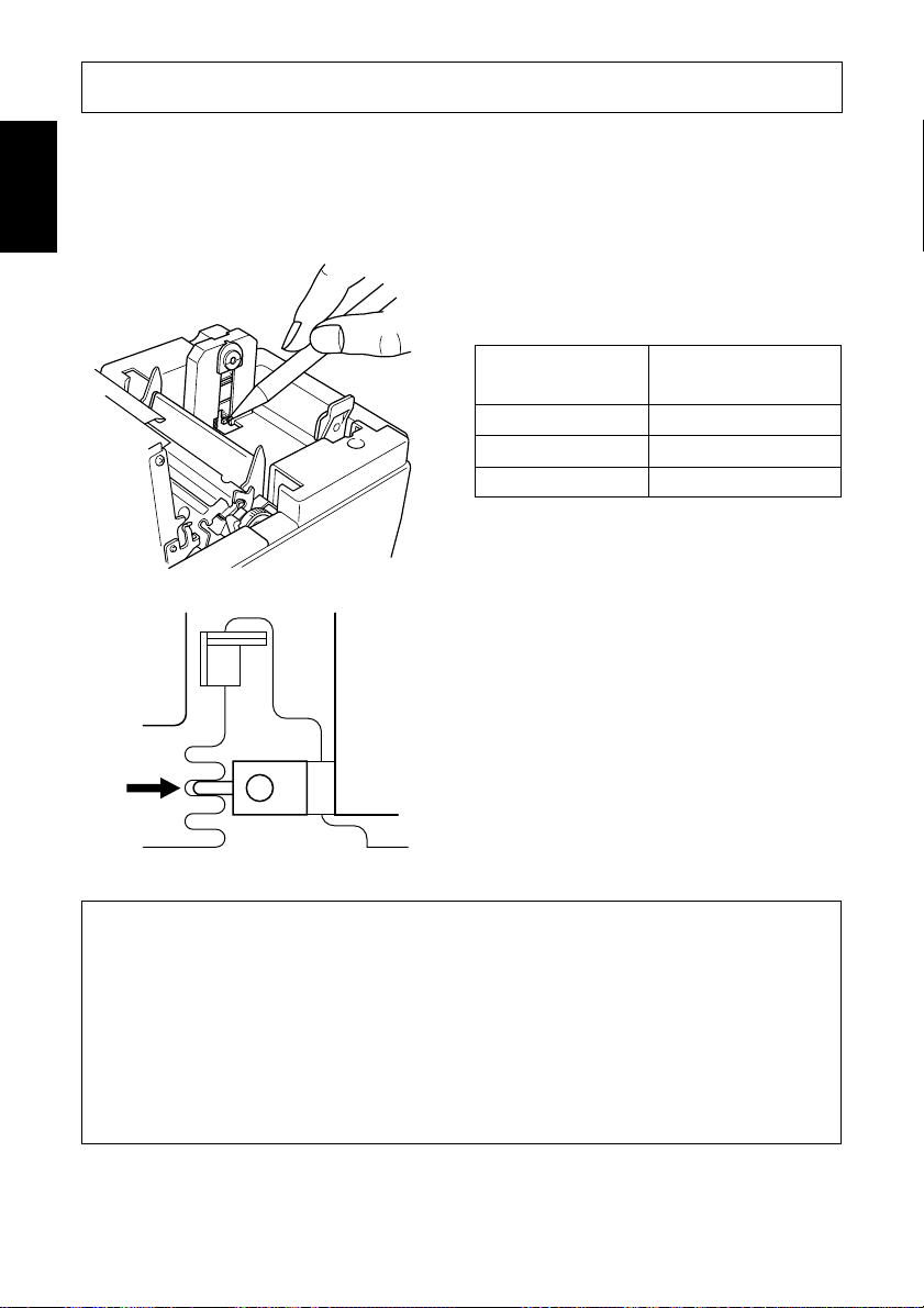
4. Near-End Sensor
ENGLISH
This printer is equipped with a sensor that detects when a roll of paper is near the
end. Read the following if you are going to use this sensor.
1 Open the cover.
2 Refer to the table below and set the
detection position for the diameter
of the roll being used.
Roll Diameter
Position
Approx. 22mm Step 1
Approx. 26mm Step 2
Approx. 30mm Step 3
3 Move the sensor and adjust the
guraduation of the sensor to the
adjusted position that corresponds
to the diameter of the roll selected.
Press this hole with a ball point pen or
similar pointed object and slide it into
position. Make sure that the protruding
section (shown by arrow) is securely in
the groove, especially at step 2.
Cautions
1) The factory setting is step 1.
2) Always use a paper roll with a core that has an inside diameter of 12 mm and
an outside diameter of 18 mm in order to ensure proper detection of the
remaining paper amount.
3) The near-end sensor is disabled when shipped from the factory. It can be
enabled by rewriting the memory switch. Refer to the “Programmer’s
Manual” for details.
Adjustment
– 8 –
Page 13
5-1. Loading Paper
5. Loading Paper
Paper roll
Core
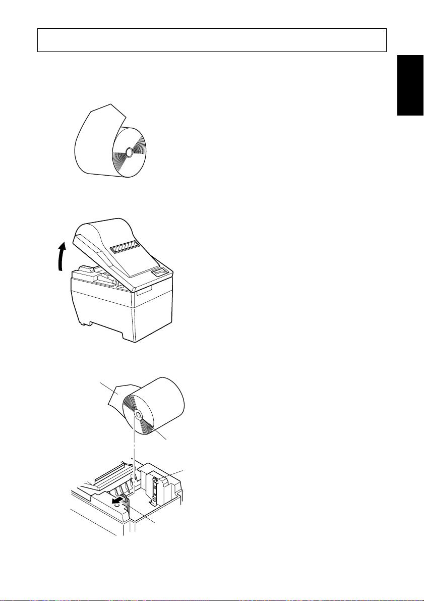
1 Procure a roll of paper and fold in
the corners as shown in the illustration.
2 Open the printer cover.
3 Open the holder lever by pressing it
in the direction indicated by the
arrow. Load the paper in the direction shown in the illustration. Make
sure that the core of the paper roll is
held securely by the holder.
ENGLISH
Holder
Holder lever
– 9 –
Page 14
ENGLISH
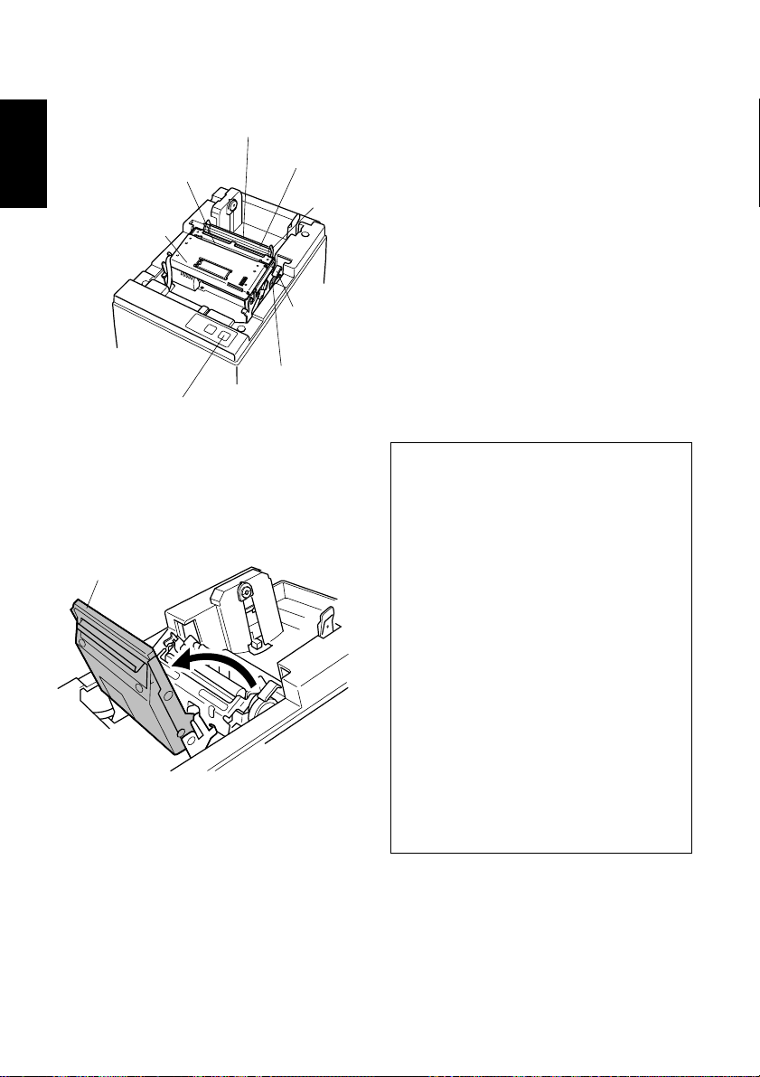
Auto cutter unit
Paper exit
Auto cutter
unit
Feed switch
Paper feeder
Paper guide
Feed knob
Support guide
Head-up lever
4 (Using the auto loading function)
• With the auto cutter installed.
1) The unit is shipped with the head-up
lever in the up position. Press the
lever back to put it in the closed
position. See “Chapter 3: Printer
Connection” for details.
2) Insert the edge of the paper into the
paper feeder. If inserted correctly,
the edge of the paper will pass
through the paper exit.
Caution
If the paper is not completely straight
when it is inserted into the unit, the
paper will “skew”
*1) and the edges
will fold. Depending upon the degree
of the skew, the flow of paper can be
automatically corrected by pressing
the FEED switch
*2) to adjust the
flow of paper. However, should the
paper become extremely skewed, a
paper jam may occur. To clear the
jam, pull the auto cutter unit all the
way back in the direction indicated
by the arrow until the lock engages.
With the lever in the “head-up” position, pull out the paper from the paper
feeder.
– 10 –
1)
Skew: When paper is fed unevenly
*
into the printer.
2)
See “Chapter 6: Control Panel” for
*
details on operating the FEED
switch.
Page 15
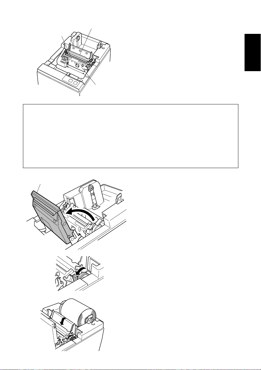
Paper feeder
Paper exit
• Without an auto paper cutter.
1) Same as 4-1.
2) Insert the edge of the paper into the
paper feeder. If inserted correctly,
the edge of the paper will pass
through the paper exit.
Printer mechanism
Caution
If the paper is not completely straight when it is inserted into the unit, the paper
will “skew” and the edges will fold. Depending upon the degree of the skew,
the flow of paper can be automatically corrected by pressing the FEED switch.
However, should the paper become extremely skewed, a paper jam may occur.
To clear the jam, pull the head-up lever forward. With the lever in the “headup” position, pull out the paper from the paper feeder.
ENGLISH
Auto cutter unit
5 (Manual loading)
1) Move the auto cutter unit all the way
back in the direction indicated by
the arrow until the lock engages
(unnecessary if an auto cutter unit is
not installed).
2) Pull the head-up lever forward into
the “head-up” position. The headup lever is shipped from the factory
in the “head-up” position.
See “Chapter 3: Printer Connection” for details.
3) Insert the edge of the paper into the
paper feeder. Turn the feed knob
(green) until the edge of the paper
passes through the printer mechanism’s paper exit.
– 11 –
Page 16
ENGLISH
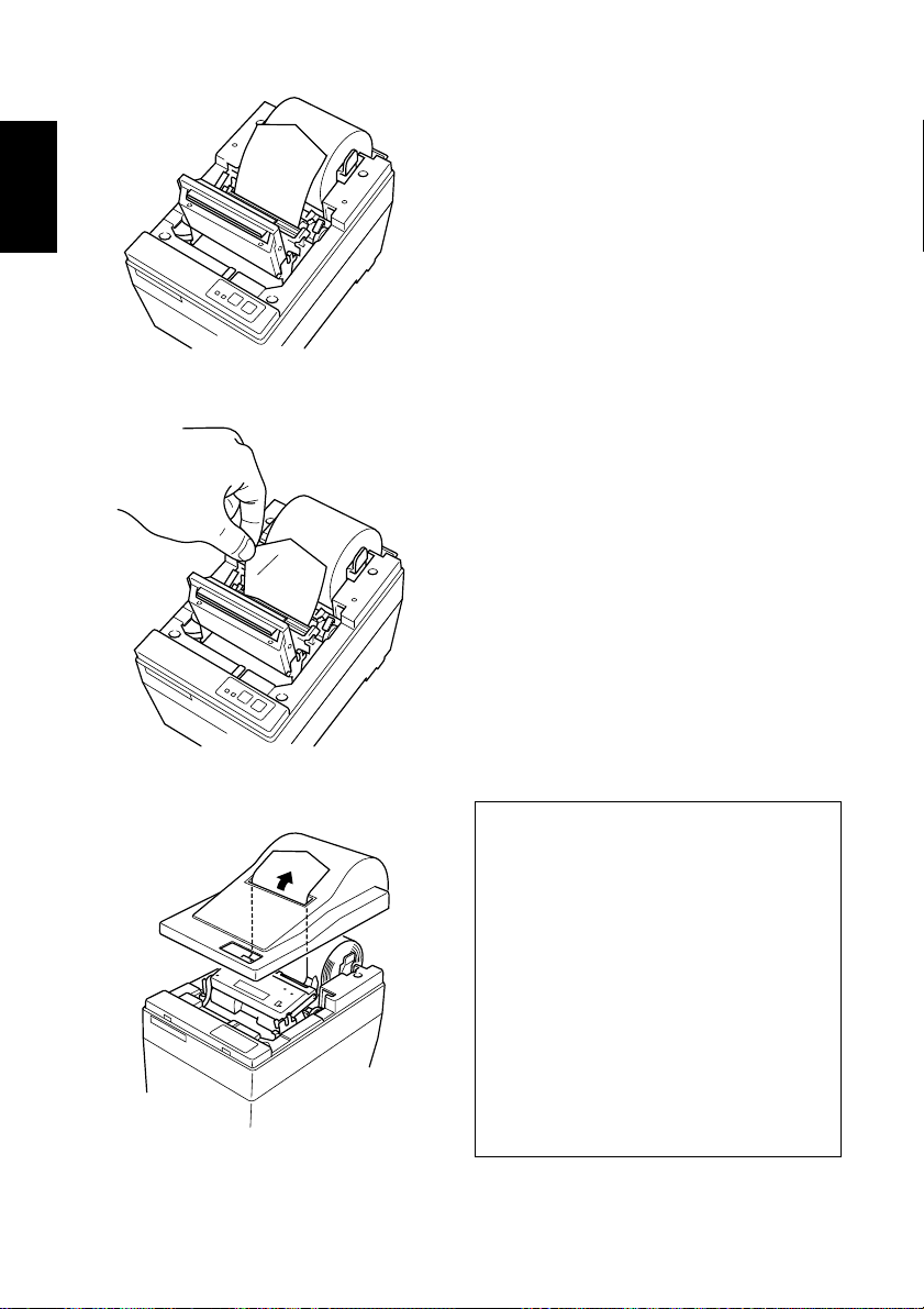
4) Once the paper has passed through
the printer mechanism’s paper exit,
pull the paper straight to correctly
position it.
5) Make sure that the paper is straight
with approximately 15-20 centimeters
exposed and lower back the head-up
cutter.
6) Take the edge of the paper and cut it
by pressing it up against the head.
Be careful not to cut yourself on the
edge of the auto cutter unit during
this step.
7) Close the auto cutter unit (unnecessary if an auto cutter unit is not
installed).
8) Close the cover, turn on the ON
LINE switch and make sure that the
ON LINE indicator turns on.
See “Chapter 6: Control Panel” for
details on the ON LINE indicator
and switch.
Caution
When using the auto loading function, part of the paper will be exposed
after loading. Be sure to pass this
length of the paper through the paper
exit of the printer cover before closing the cover.
When loading paper manually, make
sure that paper has passed through
the paper exit of the printer cover
after closing the cover and pressing
the FEED switch.
– 12 –
Page 17
5-2. Refilling the Paper Supply
1 When the paper sensor detects that
the printer is out of paper, press the
FEED switch until the paper feeding action stops. If the near-end
sensor is operating and there is still
paper on the roll, cut the paper just
in front of the paper feeder and press
the FEED switch until the paper
feeding action stops. See “Chapter
4: Near-end Sensor” for details.
2 Open the cover, pull the head-up
lever forward into the “head-up”
position and pull out the paper.
3 Open the holder lever in the direc-
tion indicated by the arrow and remove the core and any left over
paper.
4 See “5-1: Loading Paper” and fol-
low the directions provided to refill
the paper supply.
ENGLISH
– 13 –
Page 18
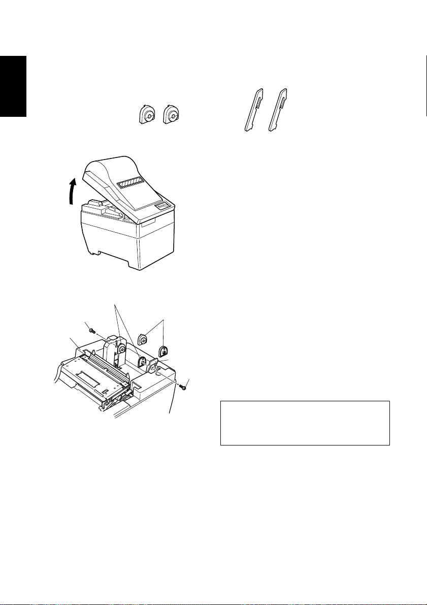
5-3. 76mm Width Support
76mm width support is an available accessory when adding to or changing the
ENGLISH
configuration of the printer.
M2 screw
Upper case
76mm holders
80mm holders
76mm holders
Holder lever
M2 screw
Support spacers
1 Open the printer cover.
2 Use a screwdriver to remove the
M2 screws that fasten the 80mm
holders to the upper case and the
holder lever. Replace the 80mm
holders with the optional 76mm
holders.
Caution
Be careful not to drop any of the
screws.
– 14 –
Page 19
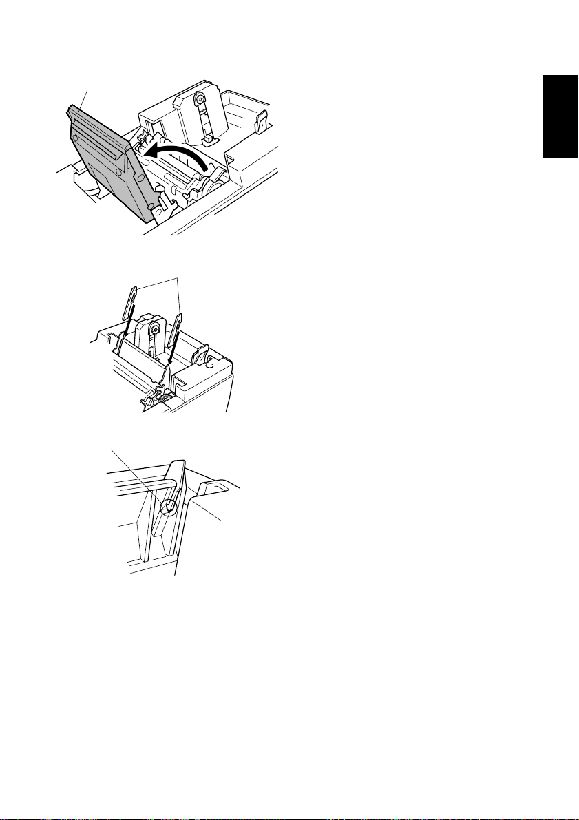
Auto cutter unit
Support spacer
Where the catch locks
3 Move the auto cutter unit in the
direction of the arrow until the lock
engages (unnecessary if an auto
cutter unit is not installed).
4 Insert the support spacers for 76mm
paper into the inner left and right
sides of the support guides as shown
in the illustration. Make sure that
the catches on the support spacers
lock onto the holes in the support
guides.
ENGLISH
5 Close the auto cutter unit (unneces-
sary if an auto cutter unit is not
installed).
– 15 –
Page 20
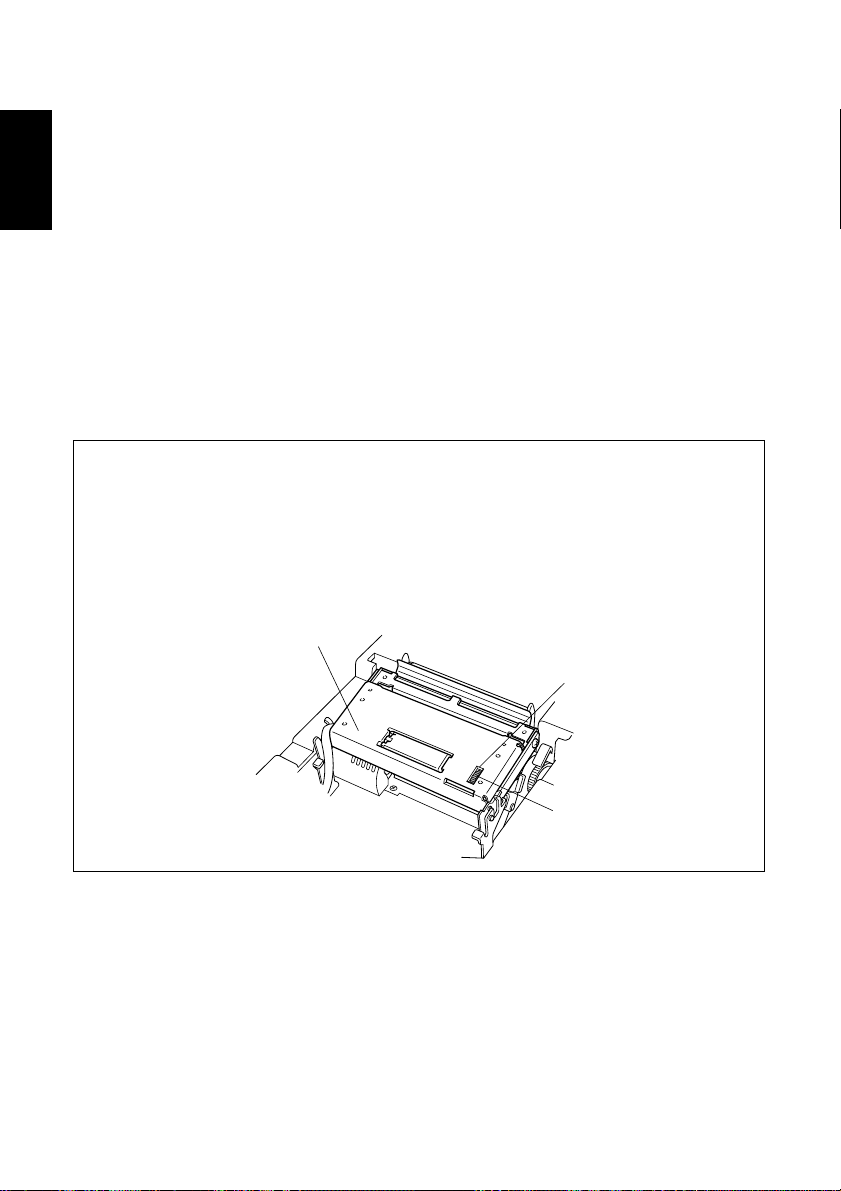
5-4. Clearing Paper Jams
ENGLISH
1 Turn the power to the printer OFF and open the cover.
2 Move the auto cutter unit in the direction of the arrow until the lock engages
(unnecessary if an auto cutter unit is not installed).
3 Cut some of the paper from the roll just in front of the paper feeder to clear the
paper jam.
4 Using the same procedure described for cleaning the head, push the head-open
lever back and release the set cover to enable the head-open position. See
“Appendix E: Cleaning” for details.
5 Clear away the jammed paper. If the jammed paper cannot be reached, turn the
feed knob and remove the paper.
6 Once the paper jam has been removed, press the top of the set cover and engage
the head-open lever.
Cautions
* If a paper jam should occur in the auto cutter, place a screwdriver into the
opening located on the upper right surface of the auto cutter unit; using the
screwdriver, turn the knob to move the blade and remove the jammed paper.
* Certain parts of the printer, especially the metal fixtures, can cause injuries if
handled improperly. Please be careful when handling the printer.
Auto cutter unit
Opening
– 16 –
Knob
Page 21
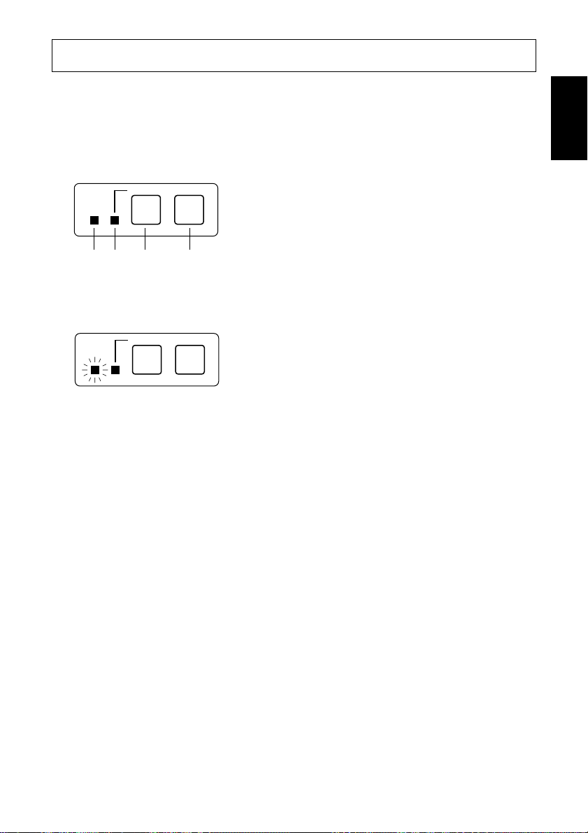
6-1. Power ON
Operating Panel
Paper - Yes
POWER
12 3 4
Paper - No
ON LINE
FEED
6. Control Panel
1 Power Lamp (Green LED)
2 On-Line Lamp (Green LED)
3 On-Line Switch
4 Feed Switch
ENGLISH
POWER
ON LINE
FEED
When the power switch is turned on, the Power Lamp and On-Line Lamp will
come on. If there is no paper, the Power Lamp will flash at approximately one
second intervals.
ON LINE Switch Indicator (Star mode only)
Used to switch between the off-line and on-line modes.
The ON LINE indicator turns on when the printer is on-line.
When the printer is off-line, printing will stop and data from the host computer
cannot be received.
FEED Switch
Each press of the FEED switch feeds paper through the printer one line at a time.
Paper is fed continuously when the FEED switch is pressed and held.
The functions of the FEED switch are supported by both the on-line and off-line
modes.
Power Indicator
The power indicator turns on when power is being supplied to the printer.
– 17 –
Page 22
6-2. Combined Control Panel Operations
The following settings can be made when the power switch is set to on.
ENGLISH
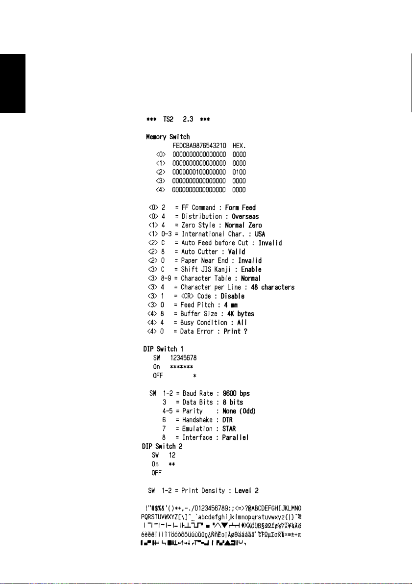
1 Test print
The buzzer will beep when the FEED switch is pressed and held while the
power is turned on.
– 18 –
Page 23
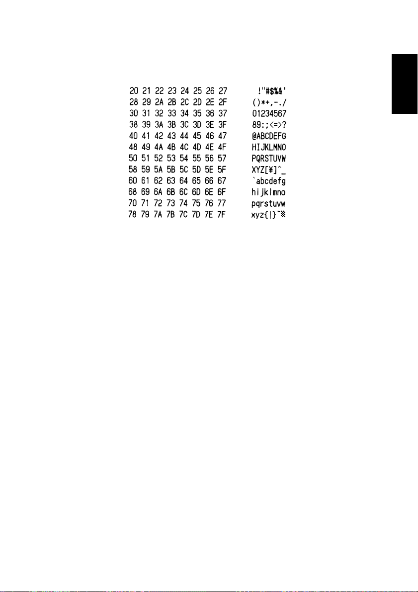
2 HEX dump
The buzzer will beep when the ON LINE switch is pressed and held while the
power is turned on.
ENGLISH
– 19 –
Page 24
6-3. Errors
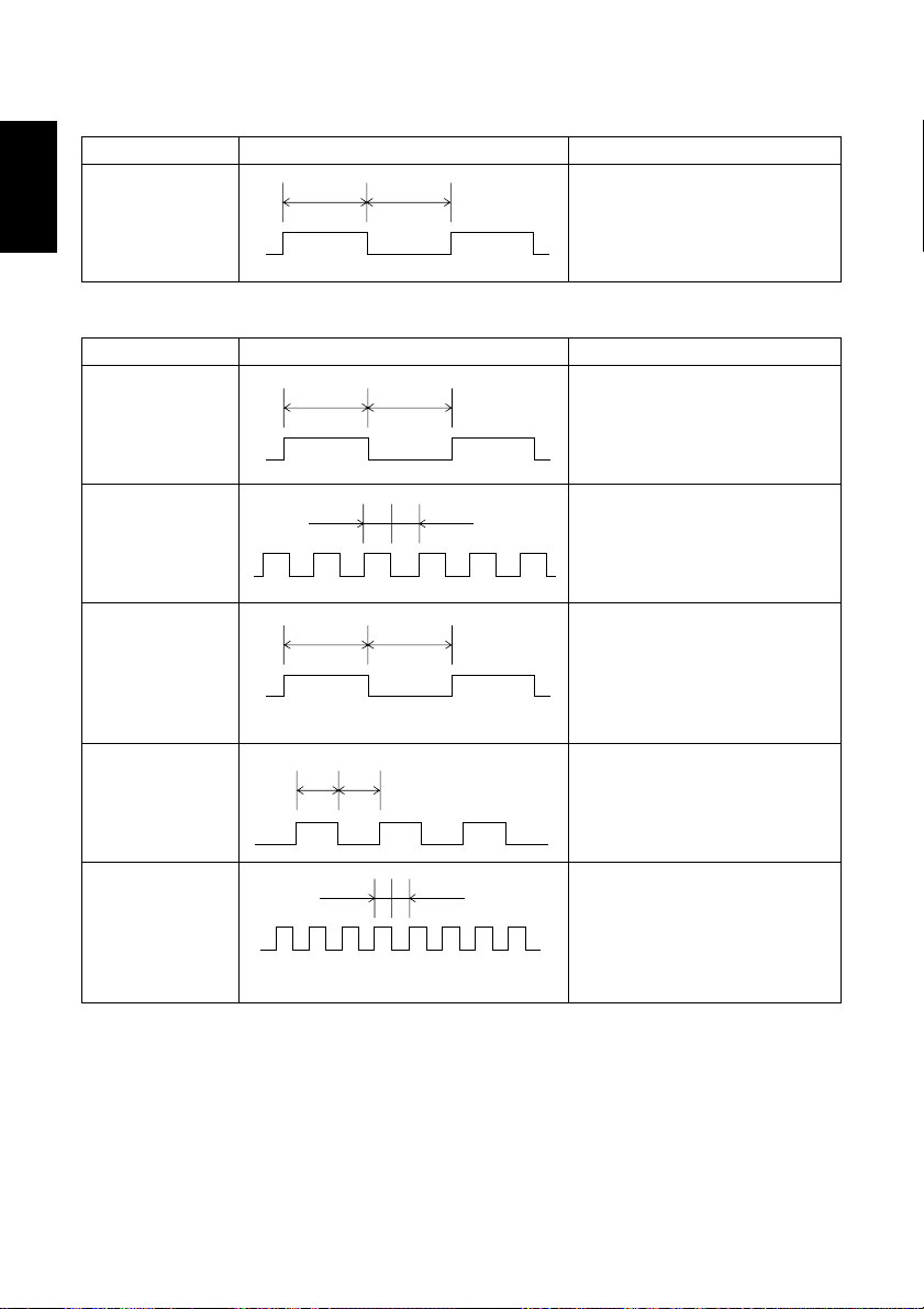
1) Automatic Recovery (Power Lamp: Flashing; On-Line Lamp: On)
ENGLISH
Error Description
Abnormal head
temperature
Power Lamp Flashing Pattern Recovery Conditions
Approx. 1 Sec Approx. 1 Sec
Automatic recovery after head
temperature lowers.
2) Recoverable Errors (Power Lamp: Flashing; On-Line Lamp: Off)
Error Description
No paper
Power Lamp Flashing Pattern Recovery Conditions
Approx. 1 Sec Approx. 1 Sec
Insert paper and press on-line
switch. (Star)
Insert paper and close cover. (ESC/
POS)
Head up
Approx. 250 msApprox. 250 ms
Lower head and press on-line
switch. (Star)
Lower head and close cover. (ESC/
POS)
Paper near end of
roll
Approx. 2 Sec Approx. 2 Sec
Press on-line switch and printing
will continue. Both lamps light
when printing and power lamp
flashes and on-line lamp lights
when on-line. (Star)
Same as “No paper”. (ESC/POS)
Cover is open
500 ms
Approx.
500 ms
Close cover and press on-line
switch. (Star)
Approx.
Close cover. (ESC/POS)
Error during paper
cutting
Approx. 125 msApprox. 125 ms
If the blade is at the home position,
press on-line switch to continue
printing. If the blade is not at the
home position, it is not a recoverable error. (Star)
Command (ESC/POS)
3) Fatal Error (Power Lamp: Flashing; On-Line Lamp: Flashing) the unit
will have to be repaired.
– 20 –
Page 25

6-4. Buzzer Indicators (Star Mode Only)
P: 50ms Pi: 100ms
1 On-line/off-line P
2 No paper error PPPP PPPP
3 Head-up error PiPiPi
4 Paper near-end sensor error PP PP
5 Cover open error PPPP
6 Cutter error Pi PPP PPiPiP PPPPPi PiPiPiPiPi PiPiPiPiPi
7 Command buzzer Pi
ENGLISH
– 21 –
Page 26

7. Cautions
ENGLISH
7-1. Operating Cautions
1 The service life of the thermal print head cannot be guaranteed if any paper
other than the recommended paper is used. There will be a noticeable decline
in the service life of the thermal element of the print head when the paper used
contains (Na+, K++, CI-).
2 Never print when there is water or any form of moisture, such as from
condensation, on the surface of the print head.
7-2. Safety Cautions
1 Never touch the thermal print head or motor during printing or immediately
after printing as these components are very hot.
2 Never touch any moving parts, such as gears or knobs, during printing.
3 Always use care near the edges of printer components, especially metal
components, as they may cause injury.
– 22 –
Page 27

8. Command summary
8-1. Star Mode
Commands to Select Characters
Control codes
<ESC> “R” n 1B 52 n Select international character set
<ESC> “/” “1” 1B 2F 31
<ESC> “/” <1> 1B 2F 01
<ESC> “/” “0” 1B 2F 30
<ESC> “/” <0> 1B 2F 00
<ESC> “b” n1 n2 n3 n4 1B 62 n1 n2 n3 n4 Select bar code printing
d1 ... <RS> d1 ... 1E
<ESC> “M” 1B 4D Select 12-dot pitch printing
<ESC> “p” 1B 70 Select 14-dot pitch printing
<ESC> “P” 1B 50 Select 15-dot pitch printing
<ESC> “:” 1B 3A Select 16-dot pitch printing
<ESC> <SP> n 1B 20 n Set character spacing
<SO> 0E Sets the printing magnified double in
<DC4> 14 Resets the printing magnified in
<ESC> “W” n 1B 57 n
<ESC> <SO> 1B 0E Sets the printing magnified double in
<ESC> <DC4> 1B 14 Resets the printing magnified in character
<ESC> “h” n 1B 68 n
<ESC> “i” n1 n2 1B 69 n1 n2 Sets the magnification rates in character
<ESC> “–” “1” 1B 2D 31
<ESC> “–” <1> 1B 2D 01
<ESC>“–” “0” 1B 2D 30
<ESC> “–” <0> 1B 2D 00
<ESC> “_” “1” 1B 5F 31
<ESC> “_” <1> 1B 5F 01
<ESC> “_” “0” 1B 5F 30
<ESC> “_” <0> 1B 5F 00
Hexadecimal
codes
Function
Select slash zero
Select normal zero
character width.
character width.
Sets the magnification rate in character width.
character height.
height.
Sets the magnification rate in character height
width and height.
Select underlining
Cancel underlining
Select overlining
Cancel overlining
ENGLISH
.
– 23 –
Page 28

Control codes
<ESC> “4” 1B 34 Select highlight printing
ENGLISH
<ESC> “5” 1B 35 Cancel highlight printing
<SI> 0F Inverted printing
<DC2> 12 Cancel inverted printing
<ESC> “E” 1B 45
<ESC> “G” 1B 47
<ESC> “F” 1B 46
<ESC> “H” 1B 48
Hexadecimal
codes
Function
Select emphasized printing
Cancel emphasized printing
Commands to Set the Page Format
Control codes
<ESC> “C” n 1B 43 n Set page length in lines
<ESC> “C” <0> n 1B 43 00 n Set page length in inches
<ESC> “N” n 1B 4E n Set bottom margin
<ESC> “O” 1B 4F Cancel bottom margin
<ESC> “l” n 1B 6C n Set left margin
<ESC> “Q” n 1B 51 n Set right margin
Hexadecimal
codes
Function
Commands to Move the Print Position
Control codes
<LF> 0A Line feed
<CR> 0D Carriage Return
<ESC> “a” n 1B 61 n Feed paper n lines
<FF> 0C Form feed
<HT> 09 Horizontal tab
<VT> 0B Vertical tab
<ESC> “z” “1” 1B 7A 31
<ESC> “z” <1> 1B 7A 01
<ESC> “0” 1B 30 Set line spacing to 3 mm
<ESC> “J” n 1B 4A n One time n/4 mm feed
<ESC> “j” n 1B 6A n One time n/4 mm backfeed
<ESC> “B” n1 n2 ... <0> 1B 42 n1 n2 ... 00 Set vertical tab stops
<ESC> “D” n1 n2 ... <0> 1B 44 n1 n2 ... 00 Set horizontal tab stops
Hexadecimal
codes
Function
Set line spacing to 4 mm
– 24 –
Page 29

Commands to Print Dot Graphics
Control codes
<ESC> “K” n <0> 1B 4B n 00 m1 m2 Print normal density graphics
m1 m2 ... ...
<ESC> “L” n1 n2 1B 4C n1 n2 m1 m2 Print high density graphics
m1 m2 ... ...
<ESC> “k” n <0> m1 ... 1B 6B n 00 m1 ... Print fine density graphics
Hexadecimal
codes
Function
Commands to Print Download Characters
Control codes
<ESC> “&” “1” “1” 1B 26 31 31 n
n m1 m2 ... m48 m1 m2 ... m48
<ESC> “&” <1> <1> 1B 26 01 01
n m1 m2 ... m48 n m1 m2 ... m48
<ESC> “&” “1” “0” n 1B 26 31 30 n
<ESC> “&” <1> <0> n 1B 26 01 00 n
<ESC> “%” “1” 1B 25 31
<ESC> “%” <1> 1B 25 01
<ESC> “%” “0” 1B 25 30
<ESC> “%” <0> 1B 25 00
Hexadecimal
codes
Function
Define download character
Delete a download character
Enable download character set
Disable download character set
ENGLISH
Commands to Control Peripheral Devices
Control codes
<ESC> <BEL> n1 n2 1B 07 n1 n2 Define drive pulse width for peripheral
<BEL> 07 Control peripheral device #1
<FS> 1C Control peripheral device #1 immediately
<EM> 19 Control peripheral device #2 immediately
<SUB> 1A Control peripheral device #2 immediately
Hexadecimal
codes
Function
device #1
– 25 –
Page 30

Commands to Control Auto Cutter
Control codes
ENGLISH
<ESC> “d” “0” 1B 64 30
<ESC> “d” <0> 1B 64 00
<ESC> “d” “1” 1B 64 31
<ESC> “d” <1> 1B 64 01
<ESC> “d” “2” 1B 64 32
<ESC> “d” <2> 1B 64 02
<ESC> “d” “3” 1B 64 33
<ESC> “d” <3> 1B 64 03
Hexadecimal
codes
Function
Full-cut command to the auto cutter
Partial-cut command to the auto cutter
Feed paper to the cutting position and perform a full-cut.
Feed paper to the cutting position and perform a partial-cut.
Other Commands
Control codes
<CAN> 18 Cancel last line & Initialize printer
<DC3> 13 Deselect printer
<DC1> 11 Set select mode
<RS> 1E Beep the buzzer
<ESC> “#N, n1 n2 n3 n4”
<LF> <NUL> 0A 00
<ESC> “@” 1B 40 Initialize printer
<ENQ> 05 Enquiry
<ESC> “?” <LF> <NUL> 1B 3F 0A 00 Reset printer hardware
Hexadecimal
codes
1B 23 N 2C n1 n2 n3 n4
Function
Set memory switch
– 26 –
Page 31

8-2. ESC/POS Mode
Control Code Hexadecimal Code Function
HT 09 Horizontal tab
LF 0A Print line feed
FF 0C Page mode print and return
DLE EOT 10 04 Real time transmission of status
DLE ENQ 10 05 Real time request to printer
CAN 18 Cancel print data in page mode
ESC FF 1B FF Print page mode data
ESC SP 1B 20 Set right space amount of character
ESC ! 1B 21 Universal print mode designation
ESC # 1B 23 Set memory switch
ESC $ 1B 24 Designate absolute printing
ESC % 1B 25 Designate/cancel download character set
ESC & 1B 26 Define download characters
ESC
*
ESC - 1B 2 D Designate/cancel underline
ESC 2 1B 32 Set 1/6 inch line feed amount
ESC 3 1B 33 Set line feed amount
ESC = 1B 3D Select peripheral equipment
ESC ? 1B 3F Delete download characters
ESC @ 1B 40 Initialize printer
ESC D 1B 44 Set horizontal tab position
ESC E 1B 45 Designate/cancel emphasized print
ESC G 1B 47 Designate/cancel double print
ESC J 1B 4A Print and paper feed
ESC L 1B 4C Select page mode
ESC R 1B 52 Select international characters
ESC S 1B 53 Select standard mode
ESC T 1B 54 Select character print direction in print mode
ESC V 1B 56 Designate/cancel 90° character rotation
ESC W 1B 57 Set print range in page mode
ESC \ 1B 5C Designate relative position
ESC a 1B 61 Align position
ESC c4 1B 63 34 Select no valid paper detector at print stop
ESC c5 1B 63 35 Enable/disable panel switch
ESC d 1B 64 Print and paper feed “n” lines
ESC i 1B 69 Partial cut (one section remaining)
ESC p 1B 70 Designate pulse generation
ESC t 1B 74 Select character code table
1B 2A Designate bit image mode
ENGLISH
– 27 –
Page 32

Control Code Hexadecimal Code Function
ENGLISH
ESC u 1B 75 Transmission of peripheral equipment status
ESC v 1B 76 Transmission of paper detection status
ESC { 1B 7B Designate/cancel inverted printing
GS ! 1D 21 Designate character size
GS $ 1D 24 Designate absolute position of vertical direction of
GS
*
GS / 1D 2F Print download bit image
GS : 1D 3A Start/finish macro definition
GS B 1D 42 Designate/cancel reverse printing
GS H 1D 48 Select print position of HRI characters
GS I 1D 49 Printer ID transmission
GS L 1D 4C Set left margin
GS P 1D 50 Set basic calculated pitch
GS V 1D 56 Paper cut
GS W 1D 57 Set print range
GS \ 1D 5C Designate the relative position of vertical characters when
GS ^ 1D 5E Execute macro
GS a 1D 61 Enable/disable automatic status transmission
GS f 1D 66 Select HRI character font
GS h 1D 68 Set bar code height
GS k 1D 6B Printing of bar code
GS r 1D 72 Transmission of status
GS w 1D 77 Set lateral size of bar code
1D 2A Define download bit image
characters in page mode
printing in the page mode
– 28 –
Page 33

Table des matières
1. Déballage et inspection........................................................................31
1-1. Déballage ...................................................................................31
1-2. Emplacement de l’imprimante ...................................................31
2. Identification des pièces et nomenclature............................................32
3. Connexion de l’imprimante .................................................................33
3-1. Câble d’interface ........................................................................33
3-2. Tore de ferrite *Uniquement pour l’Europe ..............................35
3-3. l’adaptateur secteur optionnel ....................................................37
4. Capteur de fin de rouleau ....................................................................38
5. Mise en place du papier ....................................................................... 39
5-1. Mise en place du papier .............................................................39
5-2. Changement de rouleau de papier ..............................................43
5-3. Support de 76 mm de large ........................................................44
5-4. Correction des bourrages de papier............................................46
6. Tableau de commande ......................................................................... 47
6-1. Mise sous tension .......................................................................47
6-2. Opérations combinées du panneau de commande .....................48
6-3. Erreurs........................................................................................50
6-4. Indications de la sonnerie (mode Star seulement) .....................51
7. Precautions ..........................................................................................52
7-1. Précautions relatives à l’utilisation ............................................52
7-2. Précautions relatives à la sécurité ..............................................52
FRANÇAIS
8. Resume des commandes......................................................................53
8-1. Mode Star...................................................................................53
8-2. Mode ESC/POS..........................................................................57
L’appendice n’est pas traduit.
Page 34

Page 35

1. Déballage et inspection
1-1. Déballage
Contrôler à l’aide de la figure 1-1 ci-dessous que chaque élément décrit se trouve
dans la boîte.
Si tout élément semble manquer, contacter le fournisseur.
Imprimante
Echantillon de
rouleau de papier
Supports de
76mm
Guide d’utilisation
Pièce d'écartement
du support
Tore de ferrite
pour câble
d’appareil
périphérique
(uniquement pour
l’Europe)
Attache
(uniquement
pour l’Europe)
Figure 1-1
1-2. Emplacement de l’imprimante
Avant d’entamer l’installation de l’imprimante, s’assurer que le futur emplacement est approprié. En d’autres termes, il convient que cet emplacement soit:
• à proximité d’une prise secteur d’accès aisé;
• une surface stable et de niveau non-soumise à des vibrations excessives;
• à l’abri de températures excessivement élevées (à la lumière directe du soleil,
à proximité d’appareils de chauffage, etc.)
• à l’abri de toute humidité excessive;
• à l’abri d’une quantité excessive de poussière;
• alimenté par une source secteur non-soumise à de brusques variations de
tension. Ainsi, ne pas alimenter l’imprimante via un circuit alimentant déjà un
gros consommateur de courant et producteur de bruit tel qu’un réfrigérateur
ou un climatiseur.
N.B.: S’assurer que la tension du secteur correspond bien à la tension spécifiée
par le fabricant sur la plaque d’identification de l’imprimante.
– 31 –
FRANÇAIS
Page 36

Capot
Protège l'imprimante contre
la poussière et réduit le bruit.
FRANÇAIS
Ne pas ouvrir le capot
pendant l'impression.
Connecteur de câble
d’adaptateur secteur
Ce connecteur vous permet de
connecter le câble de l’adaptateur
secteur. Ne déconnectez pas le
câble lorsque l’imprimante est
sous tension.
2. Identification des pièces et nomenclature
Tableau de commande
Ce tableau comprend
deux commandes et deux
témoins indiquant l'état de
l'imprimante.
Interrupteur
d’alimentation
Cet interrupteur vous permet
de mettre l’imprimante sous
tension et hors tension.
Connecteur d'interface
Ce connecteur permet de
raccorder l'imprimante à
l'ordinateur-hôte.
Figure 2-1 Vue externe de l’imprimante
Connecteur de circuit d'entraînement
d'appareil périphérique
Ce connecteur permet de raccorder
l'imprimante à des appareils périphériques
tels que des caisses enregistreuses, etc.
Ne pas connecter l'imprimante à un téléphone.
– 32 –
Page 37

3. Connexion de l’imprimante
Préparer les éléments suivants avant d’effectuer les connexions à l’imprimante.
Avant d’effectuer toute connexion, toujours veiller à ce que l’imprimante soit
hors tension.
• Câble d’interface
• Tore de ferrite (uniquement pour l’Europe)
• Adaptateur secteur en option
3-1. Câble d’interface
Levier de tête
d'imprimante
[Tête en position haute]
Bouton
d’avance
[Tête en position basse]
1 Ouvrir le capot.
FRANÇAIS
2 Pousser le levier vert de la tête de
l’imprimante vers l’arrière.
Attention
Si l’imprimante doit être expédiée ou
rangée pour une période prolongée,
s’assurer de toujours tirer le levier
vert de la tête de l’imprimante vers
l’avant afin d’amener la tête d’impression en position supérieure. Ceci
permet de protéger la tête thermique
et d’éviter toute déformation de la
plaque d’impression.
3 Fermer le capot.
– 33 –
Page 38

FRANÇAIS
Screwdriver
Tournevis
Vis
Screws
4 Raccorder le connecteur du câble
d’interface dans le connecteur pour
interface de l’imprimante et fixer le
connecteur de l’interface en série à
l’aide de vis ou le connecteur de
l’interface parallèle à l’aide des agrafes prévues.
– 34 –
Page 39

3-2. Tore de ferrite *Uniquement pour l’Europe
Fastener
N.B.: Effectuer les démarches ci-dessous avec un soin particulier.
■ L’imprimante est fournie avec un
filtre antibruit à tore de ferrite destiné au câble de l’appareil périphérique.
■ Le tore de ferrite est normalement
ouvert à la livraison, comme le montre la figure 3-1.
Ferrite core (28mm diameter)
Tore de ferrite (28 mm de diamètre)
• Faire passer l’attache par le tore de
ferrite.
Figure 3-3
Attache
FRANÇAIS
One loop
Une boucle
Figure 3-1
Si ce n’est pas le cas, débloquer le
système de verrouillage en plastic
du tore de ferrite à l’aide d’un objet
pointu de la manière illustrée (3-2).
Prendre garde de ne pas abîmer le
système de verrouillage lors de
l’ouverture de ce dernier.
Figure 3-2
Pull and cut
Tirer et couper
• Faire passer l’attache autours du
câble et la bloquer.
Couper la partie de l’attache ressortant
du mécanisme de blocage à l’aide d’une
paire de ciseaux.
Figure 3-4
– 35 –
Page 40

■ Serrer le tore de ferrite autours du câble d’appareil périphérique en effectuant
une boucle de la manière illustrée (3-1).
• Veiller à ne pas endommager le câble lors de l’installation du tore de ferrite.
• Le tore de ferrite doit être correctement fixé à l’aide de l’attache fournie (se
reporter aux figures 3-3 et 3-4).
• Veiller à ne pas oublier de faire une boucle dans le câble.
FRANÇAIS
Fastener
Attache
Une boucle
One loop
Connecteur
Connector
Tore de ferrite
Ferrite core
Vis M3 × 4
Screw M3×4
Connecteur de circuit
Peripheral unit drive
d’entraînement
circuit connector
d’appareil périphérique
Figure 3-5
– 36 –
Fil de masse séparé
Separate ground wire
Page 41

3-3. l’adaptateur secteur optionnel
Remarque:Avant de connecter ou déconnecter l’adaptateur secteur, veillez
à ce que l’imprimante et tous les appareils qui y sont connectés
soient hors tension. Veillez également à débrancher le câble
d’alimentation de la prise secteur.
1 Connectez l’adaptateur secteur au câble d’alimentation.
Remarque:Utilisez exclusivement l’adaptateur secteur et le câble d’alimen-
tation destinés à l’imprimante.
2 Connectez l’adaptateur à la borne de l’imprimante.
3 Branchez la prise du câble d’alimentation à la prise secteur.
Interrupteur
d'alimentation
FRANÇAIS
Figure 3-6
– 37 –
Page 42

4. Capteur de fin de rouleau
Cette imprimante est équipée d’un capteur détectant l’approche de la fin de
rouleau. Pour savoir comment utiliser cette fonction, lire les instructions cidessous.
FRANÇAIS
1 Ouvrir le capot.
2 Régler la position de détection en
fonction du diamètre du rouleau de
papier utilisé à l’aide du tableau cidessous.
Diamètre de
rouleau
Environ 22 mm Cran 1
Environ 26 mm Cran 2
Environ 30 mm Cran 3
3 Déplacer le capteur jusqu’au cran
correspondant au diamètre du rouleau employé.
Introduire la pointe d’un stylo à bille ou
d’un objet pointu similaire dans l’orifice du capteur et faire glisser ce dernier jusqu’au cran approprié. S’assurer
que l’ergot du capteur (indiqué par la
flèche sur la figure ci-contre) est correctement inséré dans le cran, tout spécialement s’il s’agit du cran 2.
Attention
1) Le capteur de fin de rouleau est positionné sur le cran 1 à la sortie d’usine.
2) Afin d’assurer une détection correcte de la quantité de papier restant sur le
rouleau, toujours employer un rouleau de papier dont les diamètres interne
et externe du rouleau de carton correspondent respectivement à 12 mm et 18
mm.
3) Le capteur de fin de rouleau n’est pas activé à la sortie d’usine. Il convient
de l’activer en modifiant le commutateur de mémorisation. Pour plus de
détails, se reporter au “Manuel du Programmeur”.
Position
– 38 –
Page 43

5. Mise en place du papier
5-1. Mise en place du papier
1 Se procurer un rouleau de papier et
plier les coins de la façon illustrée.
FRANÇAIS
2 Ouvrir le Capot.
Rouleau de
papier
Rouleau
Axe
Levier du support
3 Ecarter le levier du support en ap-
puyant dessus dans le sens de la
flèche. Installer le rouleau de papier
de la manière illustrée ci-contre.
S’assurer que le noyau du rouleau
de papier est maintenu fermement
en place par le support.
– 39 –
Page 44

FRANÇAIS
Fente de sortie
de papier
Mécanisme
de découpe
automatique
Mécanisme
de découpe
automatique
Touche
d’avance
Mécanisme
d’avance de
papier
Guide de papier
Bouton
d’avance
Guide du
support
Levier de tête
d'imprimante
4 (Utilisation de la fonction de char-
gement automatique)
• Avec le mécanisme de découpe
automatique en place.
1) L’imprimante est livrée avec le le-
vier de soulèvement de la tête d’im-
primante en position haute. Appuyer
sur le levier pour refermer la tête.
Voir “Chapitre 3 : Raccordement de
l’imprimante” pour les détails.
2) Insérer le bord du papier dans le
mécanisme d’avance de papier. S’il
est inséré correctement, le bord du
papier ressortira par la fente de sortie de papier.
Attention
Si le papier n'est pas inséré dans l'imprimante parfaitement droit, il se "mettra
en travers" *1) et les bords se plieront.
Suivant l’angle pris par le papier, il est
possible que l'avance du papier puisse
être corrigée automatiquement en appuyant sur la touche d’avance FEED
*2) pour la réguler. Néanmoins, si le
papier prend un angle trop important,
un bourrage de papier surviendra. Pour
corriger le bourrage de papier, tirer
complètement le mécanisme de dé-
coupe automatique dans le sens de la
flèche jusqu'à ce qu'il se verrouille.
Avec le levier de la tête en position
haute, tirer le papier à l'extérieur du
mécanisme d'avance de papier.
– 40 –
1)
Mise en travers : Quand le papier
*
est entraîné irrégulièrement dans
l’imprimante.
2)
*
Voir "Chapitre 6 : Tableau de commande" pour des détails sur le fonctionnement de la touche d’avance
FEED.
Page 45

Mécanisme
Fente de sortie
de papier
d’avance de
papier
• Sans mécanisme de découpe
automatique.
1) Comme pour 4-1.
2) Insérer le bord du papier dans le
mécanisme d’avance de papier. Si
le papier est inséré correctement, le
bord du papier ressortira par la fente
de sortie de papier.
Mécanisme
d’impression
Attention
Si le papier n’est pas inséré dans l’imprimante parfaitement droit, il se “mettra
en travers” et les bords se plieront. Suivant l’angle pris par le papier, il est
possible que l’avance du papier puisse être corrigée automatiquement si vous
appuyez sur la touche d’avance FEED pour la réguler. Néanmoins, si le papier
prend un angle trop important, un bourrage de papier surviendra. Pour dégager
le bourrage de papier, tirer le levier de soulèvement de la tête d’imprimante vers
l’avant. Avec le levier de la tête en position haute, tirer le papier à l’extérieur
du mécanisme d’avance de papier.
FRANÇAIS
Mécanisme de découpe
automatique
5 (Chargement manuel)
1) Tirer complètement le mécanisme
de découpe automatique dans le sens
de la flèche jusqu’à ce qu’il se ver-
rouille (ignorer cette étape si l’ap-
pareil ne dispose pas de mécanisme
de découpe automatique).
2) Tirer le levier de soulèvement de la
tête d’imprimante vers l’avant pour
mettre la tête en position haute.
L’imprimante est livrée avec le le-
vier de soulèvement de la tête d’im-
primante dans cette position.
Voir “Chapitre 3 : Raccordement de
l’imprimante” pour les détails.
3) Insérer le bord du papier dans le mé-
canisme d’avance de papier. Tourner
le bouton d’avance de papier (vert)
jusqu’à ce que le bord du papier ressorte par la fente de sortie de papier du
mécanisme d’impression.
– 41 –
Page 46

FRANÇAIS
4) Une fois que le papier est ressorti par la
fente de sortie de papier du mécanisme d’impression, tirer tout droit
sur le papier pour corriger sa position.
5) S’assurer que le papier est bien droit
avec environ 15 à 20 centimètres
exposés , puis abaisser la tête qui
était en position haute.
6) Saisir le bord du papier et le couper
en appuyant ce dernier contre la
tête. Faire attention à ne pas se cou-
per sur le bord tranchant du méca-
nisme de découpe automatique.
7) Refermer le mécanisme de découpe
automatique (ignorer cette étape si
l’appareil ne dispose pas de méca-
nisme de découpe automatique).
8) Refermer le capot, appuyer sur le
commutateur ON LINE (en ligne)
et s’assurer que le témoin ON LINE
s’allume.
Voir “Chapitre 6 : Tableau de com-
mande” pour des détails sur le té-
moin et le commutateur ON LINE.
Attention
En cas de chargement automatique,
une partie du papier sera exposée
après le chargement. Veiller à faire
passer cette longueur de papier dans
la sortie de papier du capot de l’im-
primante avant de refermer le capot.
En cas de chargement manuel, s’assurer que le papier est passé dans la
sortie de papier du capot de l’impri-
mante après la fermeture du capot et
une pression sur la touche d’avance
FEED.
– 42 –
Page 47

5-2. Changement de rouleau de papier
1 Quand le capteur de papier détecte
l’absence de papier dans l’impri-
mante, appuyer sur la touche FEED
jusqu’à ce que l’avance du papier
cesse. Quand le capteur de fin de
rouleau proche fonctionne alors qu’il
reste du papier sur le rouleau, couper le papier juste avant le mécanisme d’avance de papier et appuyer sur la touche FEED jusqu’à
ce que l’avance du papier cesse.
Voir “Chapitre 4 : Capteur de fin de
rouleau proche” pour des détails.
2 Ouvrir le capot et tirer le levier de
soulèvement de la tête d’imprimante
vers l’avant pour mettre cette der-
nière en position haute, puis tirer sur
le papier pour l’extraire.
3 Tirer le levier du support dans le
sens de la flèche et enlever le noyau
et tout le papier restant.
4 Voir”5-1 : Mise en place du papier:
et suivre les instructions fournies
pour changer le rouleau de papier.
FRANÇAIS
– 43 –
Page 48

5-3. Support de 76 mm de large
Un support de 76 mm de large est disponible pour compléter ou modifier la
configuration de l’imprimante.
FRANÇAIS
Partie
supérieure
Supports de 80 mm
Vis M2
Supports de 76 mm
Supports de 76 mm
Levier du
support
Vis M2
Pièce d’écartement du support
1 Ouvrir le capot.
2 Utiliser un tournevis pour enlever
les vis M2 qui attachent les supports de 80 mm à la partie supé-
rieure du coffret et au levier du
support. Remplacer les supports de
80 mm par les supports de 76 mm en
option.
Attention
Faire attention à ne laisser tomber
aucune des vis.
– 44 –
Page 49

Mécanisme de
découpe
automatique
Pièce d’écartement du support
Quand une encoche
s’encliquette
3 Déplacer le mécanisme de découpe
automatique dans le sens de la flè-
che jusqu’à ce qu’il se verrouille
(ignorer cette étape si l’appareil ne
dispose pas de mécanisme de dé-
coupe automatique).
FRANÇAIS
4 Insérer les pièces d’espacement de
support pour papier de 76 mm à
l’intérieur, des côtés gauche et droit
des guides du support comme indiqué dans l’illustration. Veiller à ce
que les encoches des pièces d’espa-
cement de support s’encliquettent
dans les trous des guides de support.
5 Refermer le mécanisme de découpe
automatique (ignorer cette étape si
l’appareil ne dispose pas de méca-
nisme de découpe automatique).
– 45 –
Page 50

5-4. Correction des bourrages de papier
1 Mettre l’imprimante hors tension et ouvrir le capot.
2 Déplacer le mécanisme de découpe automatique dans le sens de la flèche
jusqu’à ce qu’il se verrouille (ignorer cette étape si l’appareil ne dispose pas
de mécanisme de découpe automatique).
3 Couper un peu de papier du rouleau devant la sortie du mécanisme d’avance
FRANÇAIS
de papier pour corriger le bourrage de papier.
4 En utilisant la procédure décrite pour le nettoyage de la tête, pousser le levier
de soulèvement de la tête vers l’arrière et libérer le cache pour permettre
l’ouverture de la tête. Voir “Appendice E : Nettoyage” pour des détails.
5 Corriger le bourrage de papier. Si cela est impossible, tourner le bouton
d’avance et retirer le papier.
6 Une fois le bourrage de papier corrigé, appuyer sur le dessus du cache de sorte
à bloquer ce dernier via les leviers d’ouverture de la tête de l’imprimante.
Attention
* Si un bourrage de papier survient dans le mécanisme de découpe automatique,
insérer un tournevis dans l’ouverture se trouvant sur la surface supérieure
droite du mécanisme de découpe automatique; en utilisant le tournevis,
tourner le bouton pour déplacer la lame et enlever le papier coincé.
* Certaines parties de l’imprimante, en particulier les pièces métalliques,
peuvent provoquer des blessures si elles sont manipulées de façon incorrecte.
Faire très attention pour la manipulation de l’imprimante.
Mécanisme
de découpe
automatique
Ouverture
– 46 –
Bouton
Page 51

6. Tableau de commande
6-1. Mise sous tension
Tableau de commande
Papier chargé
1 Témoin d’alimentation POWER
(DEL verte)
POWER
ON LINE
FEED
2 Témoin ON LINE (en ligne) (DEL
verte)
3 Commutateur ON LINE (en ligne)
4 Touche d’avance FEED
12 3 4
Pas de papier chargé
POWER
ON LINE
FEED
Lorsque l’imprimante est mise sous tension, les témoins d’alimentation POWER
et ON LINE (en ligne) s’allument. Si l’imprimante ne contient pas de papier, le
témoin POWER clignote à intervalles d’environ une seconde.
Témoin de commutateur ON LINE (mode Star seulement)
Utiliser pour commuter entre les modes hors ligne et en ligne.
Le témoin ON LINE s’allume quand l’imprimante est en ligne.
Quand l’imprimante est hors ligne, L’impression s’arrête et les données de
l’ordinateur hôte ne peuvent pas être reçues.
FRANÇAIS
Touche d’avance FEED
A chaque pression sur la touche d’avance FEED, le papier avance dans l’impri-
mante une ligne à la fois. Le papier avance en continu quand vous maintenez la
touche FEED enfoncée.
Les fonctions de la touche FEED sont supportées aussi bien dans le mode en ligne
que dans le mode hors ligne.
Témoin d’alimentation POWER
Le témoin d’alimentation POWER s’allume quand l’imprimante est sous tension.
– 47 –
Page 52

6-2. Opérations combinées du panneau de commande
Les réglages suivants peuvent être effectués quand l’imprimante est sous tension.
1 Essai d’impression
Une sonnerie retentit quand la touche FEED est maintenue enfoncée alors que
l’imprimante est sous tension.
FRANÇAIS
– 48 –
Page 53

2 Vidage hexadécimal
Une sonnerie retentit quand le commutateur ON LINE est maintenue enfoncé
alors que l’imprimante est sous tension.
FRANÇAIS
– 49 –
Page 54

6-3. Erreurs
1) Erreurs à correction automatique (témoin POWER clignotant; témoin
ON LINE allumé)
Description de l’erreur
T° anormale de la
tête
FRANÇAIS
2) Erreurs corrigibles (témoin POWER clignotant; témoin ON LINE éteint)
Description de l’erreur
Pas de papier
chargé
Cycle de clignotement du témoin POWER Correction d’erreur
Environ 1 sec.
Approx. 1 Sec Approx. 1 Sec
Environ 1 sec.
Correction automatique après
baisse de la t° de la tête.
Cycle de clignotement du témoin POWER Correction d’erreur
Environ 1 sec.
Approx. 1 Sec Approx. 1 Sec
Environ 1 sec.
Insérer le papier et appuyer sur le
commutateur ON-LINE. (Star)
Insérer le papier et refermer le
capot. (ESC/POS)
Tête en position
supérieure
Fin du rouleau de
papier proche
Le couvercle est
ouvert.
Erreur durant la
découpe du papier
Environ 250 ms Environ 250 ms
Approx. 2 Sec Approx. 2 Sec
Environ 2 sec. Environ 2 sec.
Environ
Environ
500 ms
500 ms
Environ 125 ms Environ 125 ms
Approx. 250 msApprox. 250 ms
Approx. 125 msApprox. 125 ms
Abaisser la tête d’impression et
appuyer sur le commutateur ONLINE. (Star)
Abaisser la tête d’impression et
refermer le capot. (ESC/POS)
Appuyer sur le commutateur ONLINE et l’impression se poursuit.
Les deux témoins sont allumés
pendant l’impression ; le témoin
POWER clignote et le témoin ONLINE est allumé lorsque l’appareil
est en ligne. (Star)
Voir l’erreur “Pas de papier”.
(ESC/POS)
Refermer le capot et appuyer sur le
commutateur ON-LINE. (Star)
Refermer le capot. (ESC/POS)
Si la lame est à sa position
d’origine, appuyer sur commutateur
ON-LINE afin de poursuivre
l’impression. Si la lame n’est pas à
sa position d’origine, l’erreur n’est
pas réparable. (Star)
Commande (ESC/POS)
3) Erreur non-corrigible (témoin POWER clignotant; témoin ON LINE
clignotant), il convient de faire réparer l’imprimante.
– 50 –
Page 55

6-4. Indications de la sonnerie (mode Star seulement)
P : 50 ms Pi : 100ms
1 En ligne/hors ligne P
2 Erreur pas de papier PPPP PPPP
3 Erreur tête en position haute PiPiPi
Erreur capteur de fin de rouleau proche
4
5 Erreur capot ouvert PPPP
6 Erreur mécanisme de découpe
7 Sonnerie de commande Pi
PP PP
Pi PPP PPiPiP PPPPPi PiPiPiPiPi PiPiPiPiPi
FRANÇAIS
– 51 –
Page 56

7. Precautions
7-1. Précautions relatives à l’utilisation
1 La durée de vie de la tête d’imprimante thermique ne peut être garantie si tout
autre papier que celui recommandé est employé. Si le papier utilisé contient
FRANÇAIS
du Na+, K++, CI–, la durée de vie de l’élément thermique de la tête
d’impression sera considérablement réduite.
2 Ne jamais effectuer d’impression lorsque la surface de la tête d’impression est
couverte d’eau ou de toute forme d’humidité, telle que la condensation.
7-2. Précautions relatives à la sécurité
1 Ne jamais toucher la tête d’imprimante thermique ou le moteur durant
l’impression ou immédiatement après l’impression. En effet, ces éléments
sont alors extrêmement chauds.
2 Ne jamais toucher les éléments mobiles tels que les rouages ou les boutons
durant l’impression.
3 Les bords des éléments de l’imprimante, surtout ceux en métal, sont à manier
avec une prudence particulière. En effet, ceux-ci pourraient causer des
blessures.
– 52 –
Page 57

8. Resume des commandes
8-1. Mode Star
Commandes de sélection de caractères
Code de contrôle
<ESC> “R” n 1B 52 n Sélection du jeu de caractères internationaux
<ESC> “/” “1” 1B 2F 31
<ESC> “/” <1> 1B 2F 01
<ESC> “/” “0” 1B 2F 30
<ESC> “/” <0> 1B 2F 00
<ESC> “b” n1 n2 n3 n4 1B 62 n1 n2 n3 n4
d1 ... <RS> d1 ... 1E
<ESC> “M” 1B 4D Sélection d’impression de pas 12 points
<ESC> “p” 1B 70 Sélection d’impression de pas 14 points
<ESC> “P” 1B 50 Sélection d’impression de pas 15 points
<ESC> “:” 1B 3A Sélection d’impression de pas 16 points
<ESC> <SP> n 1B 20 n Réglage d’espacement de caractère
<SO> 0E Réglage d’impression d’agrandissement
<DC4> 14 Nouveau réglage d’impression d’agrandissement
<ESC> “W” n 1B 57 n Réglage d’agrandissement de largeur de caractère
<ESC> <SO> 1B 0E Réglage d’impression d’agrandissement
<ESC> <DC4> 1B 14 Nouveau réglage d’impression d’agrandissement
<ESC> “h” n 1B 68 n Réglage d’agrandissement de hauteur de caractère
<ESC> “i” n1 n2 1B 69 n1 n2 Réglage d’agrandissements de largeur et de
<ESC> “–” “1” 1B 2D 31
<ESC> “–” <1> 1B 2D 01
<ESC>“–” “0” 1B 2D 30
<ESC> “–” <0> 1B 2D 00
<ESC> “_” “1” 1B 5F 31
<ESC> “_” <1> 1B 5F 01
<ESC> “_” “0” 1B 5F 30
<ESC> “_” <0> 1B 5F 00
Codes
hexadécimaux
Fonction
Sélection du zéro barré
Sélection du zéro normal
Sélection d’impression de code à barres
double de largeur de caractère
de largeur de caractère
double de hauteur de caractère
de hauteur de caractère
hauteur de caractère
Sélection de soulignement
Annulation de soulignement
Sélection de surlignement
Annulation de surlignement
FRANÇAIS
– 53 –
Page 58

Code de contrôle
<ESC> “4” 1B 34 Sélection d’impression surintensifiée
<ESC> “5” 1B 35 Annulation d’impression surintensifiée
<SI> 0F Impression inversée
<DC2> 12 Annulation d’impression inversée
<ESC> “E” 1B 45
FRANÇAIS
<ESC> “G” 1B 47
<ESC> “F” 1B 46
<ESC> “H” 1B 48
Codes
hexadécimaux
Fonction
Sélection d’impression mise en valeur
Annulation d’impression mise en valeur
Commandes de réglage du format de page
Code de contrôle
<ESC> “C” n 1B 43 n Réglage de la longueur de page en lignes
<ESC> “C” <0> n 1B 43 00 n Réglage de la longueur de page en pouces
<ESC> “N” n 1B 4E n Réglage de la marge inférieure
<ESC> “O” 1B 4F Annulation de la marge inférieure
<ESC> “l” n 1B 6C n Réglage de la marche gauche
<ESC> “Q” n 1B 51 n Réglage de la marge droite
Codes
hexadécimaux
Fonction
Commandes de déplacement de la position d’impression
Code de contrôle
<LF> 0A Avance de ligne
<CR> 0D Retour de chariot
<ESC> “a” n 1B 61 n Avance de n lignes de papier
<FF> 0C Saut de page
<HT> 09 Tabulation horizontale
<VT> 0B Tabulation verticale
<ESC> “z” “1” 1B 7A 31
<ESC> “z” <1> 1B 7A 01
<ESC> “0” 1B 30 Réglage d’espacement de ligne à 3 mm
<ESC> “J” n 1B 4A n Avance de n/4 mm à la fois
<ESC> “j” n 1B 6A n Recul de n/4 mm à la fois
<ESC> “B” n1 n2 ... <0> 1B 42 n1 n2 ... 00 Réglage d’arrêts de tabulation verticale
<ESC> “D” n1 n2 ... <0> 1B 44 n1 n2 ... 00 Réglage d’arrêts de tabulation horizontale
Codes
hexadécimaux
Fonction
Réglage d’espacement de ligne à 4 mm
– 54 –
Page 59

Commandes d’impression de graphiques en points
Code de contrôle
<ESC> “K” n <0> 1B 4B n 00 m1 m2
m1 m2 ... ...
<ESC> “L” n1 n2 1B 4C n1 n2 m1 m2
m1 m2 ... ...
<ESC> “k” n <0> m1 ... 1B 6B n 00 m1 ... Impression de graphiques densité fine
Codes
hexadécimaux
Fonction
Impression de graphiques densité normale
Impression de graphiques haute densité
Commandes d’impression de caractères téléchargés
Code de contrôle
<ESC> “&” “1” “1” 1B 26 31 31 n
n m1 m2 ... m48 m1 m2 ... m48
<ESC> “&” <1> <1> 1B 26 01 01
n m1 m2 ... m48 n m1 m2 ... m48
<ESC> “&” “1” “0” n 1B 26 31 30 n
<ESC> “&” <1> <0> n 1B 26 01 00 n
<ESC> “%” “1” 1B 25 31
<ESC> “%” <1> 1B 25 01
<ESC> “%” “0” 1B 25 30
<ESC> “%” <0> 1B 25 00
Codes
hexadécimaux
Fonction
Définition de caractère téléchargé
Suppression de caractère téléchargé
Validation d’un jeu de caractères téléchargés
Invalidation d’un jeu de caractères téléchargés
FRANÇAIS
Commandes de pilotage des périphériques
Code de contrôle
<ESC> <BEL> n1 n2 1B 07 n1 n2 Définition de la largeur d’impulsion d’entraîne-
<BEL> 07 Pilotage du périphérique #1
<FS> 1C Pilotage immédiat du périphérique #1
<EM> 19 Pilotage immédiat du périphérique #2
<SUB> 1A Pilotage immédiat du périphérique #2
Codes
hexadécimaux
Fonction
ment du périphérique #1
– 55 –
Page 60

Commandes de pilotage du mécanisme automatique de découpe
Code de contrôle
<ESC> “d” “0” 1B 64 30 Commande de découpe complète au mécanisme
<ESC> “d” <0> 1B 64 00 automatique
<ESC> “d” “1” 1B 64 31 Commande de découpe partielle au mécanisme
<ESC> “d” <1> 1B 64 01 automatique
FRANÇAIS
<ESC> “d” “2” 1B 64 32 Avance du papier sur la position de découpe et
<ESC> “d” <2> 1B 64 02 découpe complète du papier.
<ESC> “d” “3” 1B 64 33 Avance du papier sur la position de découpe et
<ESC> “d” <3> 1B 64 03 découpe partielle du papier.
Codes
hexadécimaux
Fonction
Autres commandes
Code de contrôle
<CAN> 18 Annulation de la dernière ligne et initialisation
<DC3> 13 Désélection de l’imprimante
<DC1> 11 Réglage du mode de sélection
<RS> 1E Retentissement de l’avertisseur
<ESC> “#N, n1 n2 n3 n4”
<LF> <NUL> 0A 00
<ESC> “@” 1B 40 Initialisation de l’imprimante
<ENQ> 05 Interrogation
<ESC> “?” <LF> <NUL> 1B 3F 0A 00 Initialisation de l’imprimante
Codes
hexadécimaux
1B 23 N 2C n1 n2 n3 n4
Fonction
de l’imprimante
Réglage du commutateur de mémorisation
– 56 –
Page 61

8-2. Mode ESC/POS
Code de
commande
HT 09 Tabulation horizontale
LF 0A Avance de ligne
FF 0C Impression mode de page et retour
DLE EOT 10 04 Transmission d’état en temps réel
DLE ENQ 10 05 Demande à l’imprimante en temps réel
CAN 18 Annulation des données d’impression en mode de page
ESC FF 1B FF Impression des données en mode de page
ESC SP 1B 20 Réglage d’espacement des caractères
ESC ! 1B 21 Désignation du mode d’impression universel
ESC # 1B 23 Commutateur de réglage de la mémoire
ESC $ 1B 24 Désignation de l’impression absolue
ESC % 1B 25 Désignation/annulation du jeu de caractères téléchargés
ESC & 1B 26 Définition des caractères téléchargés
ESC
*
ESC - 1B 2 D Désignation/annulation du soulignement
ESC 2 1B 32 Réglage de l’avance de ligne de 1/6ème de pouce
ESC 3 1B 33 Réglage de l’avance de ligne
ESC = 1B 3D Sélection de l’équipement périphérique
ESC ? 1B 3F Effacement des caractères téléchargés
ESC @ 1B 40 Initialisation de l’imprimante
ESC D 1B 44 Réglage de la position de la tabulation horizontale
ESC E 1B 45 Désignation/annulation d’impression mise en valeur
ESC G 1B 47 Désignation/annulation d’impression double
ESC J 1B 4A Impression et avance de papier
ESC L 1B 4C Sélection du mode de page
ESC R 1B 52 Sélection des caractères internationaux
ESC S 1B 53 Sélection du mode standard
ESC T 1B 54 Sélection de la direction d’impression des caractères en
ESC V 1B 56 Désignation/annulation de la rotation de 90° des caractères
ESC W 1B 57 Réglage de la plage d’impression en mode de page
ESC \ 1B 5 C Désignation de la position relative
ESC a 1B 61 Alignement de la position
ESC c4 1B 63 34 Pas de sélection de papier valide à l’arrêt d’impression
ESC c5 1B 63 35 Activation/désactivation des commandes du panneau
ESC d 1B 64 Impression et alimentation du papier de “n” lignes
ESC i 1B 69 Découpe partielle (une partie reste attachée)
ESC p 1B 70 Désignation de la génération d’impulsions
ESC t 1B 74 Sélection du tableau des codes de caractères
Code hexadécimal Fonction
1B 2A Désignation du mode d’image de bit
mode d’impression
FRANÇAIS
– 57 –
Page 62

Code de
commande
ESC u 1B 75 Transmission de l’état de l’équipement périphérique
ESC v 1B 76 Transmission de l’état de détection du papier
ESC { 1B 7B Désignation/annulation de l’impression inversée
GS ! 1D 21 Désignation de la taille de caractères
GS $ 1D 24 Désignation de la position absolue de la direction verticale
FRANÇAIS
GS
*
GS / 1D 2F Impression de l’image bit téléchargée
GS : 1D 3A Début/fin de la définition macro
GS B 1D 42 Désignation/annulation de l’impression à l’envers
GS H 1D 48 Sélection de la position d’impression des caractères HRI
GS I 1D 49 Transmission de l’identification de l’imprimante
GS L 1D 4C Réglage de la marge de gauche
GS P 1D 50 Réglage du pas calculé de base
GS V 1D 56 Coupure du papier
GS W 1D 57 Réglage de la plage d’impression
GS \ 1D 5C Désignation de la position relative des caractères verticaux
GS ^ 1D 5E Exécution de macro
GS a 1D 61 Activation/désactivation de la transmission de l’état
GS f 1D 66 Sélection de fonte de caractères HRI
GS h 1D 68 Réglage de la hauteur de codes à barres
GS k 1D 6B Impression de codes à barres
GS r 1D 72 Transmission d’état
GS w 1D 77 Réglage de la taille latérale de codes à barres
Code hexadécimal Fonction
des caractères en mode de page
1D 2A Définition de l’image bit téléchargée
lors de l’impression en mode de page
automatique
– 58 –
Page 63

Inhaltsverzeichnis
1. Auspacken und Prüfung ......................................................................61
1-1. Auspacken..................................................................................61
1-2. Wahl eines Aufstellungsorts ......................................................61
2. Funktion und Bezeichnung der Teile ..................................................62
3. Druckerverbindung..............................................................................63
3-1. Schnittstellenkabel .....................................................................63
3-2. Ferritkern *nur Europa...............................................................65
3-3. Optionales Netzteil.....................................................................67
4. Papiervorrat-Sensor .............................................................................68
5. Papier einlegen ....................................................................................69
5-1. Papier einlegen...........................................................................69
5-2. Nachfüllen der Papierversorgung...............................................73
5-3. 76 mm Breit-Stütze ....................................................................74
5-4. Papierstau beheben.....................................................................76
6. Bedienfeld............................................................................................77
6-1. Einschalten .................................................................................77
6-2. Kombinierte Bedienfeld-Verfahren ...........................................78
6-3. Fehlermeldungen........................................................................80
6-4. Signalton-Anzeigen (nur Star-Modus).......................................81
7. Behandlung des Druckers....................................................................82
7-1. Vorsichtsmaßregeln zum Betrieb...............................................82
7-2. Sicherheitsregeln ........................................................................82
DEUTSCH
8. Zusammenfassung der Befehle............................................................ 83
8-1. Star-Betriebsart ..........................................................................83
8-2. ESC/POS Betrieb .......................................................................87
Der Anhand dieser Bedienungsanleitung ist nur in englischer Sprache.
Page 64

Page 65

1. Auspacken und Prüfung
1-1. Auspacken
Überprüfen Sie an Hand von Abbildung 1 die Teile in der Verpackung, und stellen
Sie sicher, daß alle nötigen Positionen geliefert wurden; es sollten fünf sein.
Falls eines der Teile fehlen sollte, wenden Sie sich bitte an Ihren Händler.
StützDistanzstücke
Ferritkern für
PeripheriegerätKabel (nur EU)
Kabelband
(nur EU)
Drucker
Mitgelieferte
Papierrolle
Abb. 1-1
76mm Haiter
Bedienungsanleitung
1-2. W ahl eines Aufstellungsorts
Bevor Sie mit der Aufstellung des Druckers beginnen, stellen Sie sicher, daß ein
geeigneter Aufstellungsort vorhanden ist. Mit “geeignetem Aufstellungsort” ist
ein Ort gemeint, der folgenden Bedingungen entspricht:
• Nahe an einer gut zugänglichen Steckdose
• Feste, ebene Oberfläche mit geringen Vibrationen
• Ausreichender Abstand zu Hitzequellen (wie direktem Sonnenlicht, Heizkör-
pern etc.)
• Keine zu hohe Luftfeuchtigkeit
• Wenig Staub
• Zugang zu einer Netzsteckdose, die keine Spannungsschwankungen auf-
weist. So sollte der Drucker z.B. nicht an die gleiche Steckdose wie ein großes,
Störungen erzeugendes Haushaltsgerät wie ein Kühlschrank oder eine Klimaanlage angeschlossen werden.
HINWEIS: Sicherstellen, daß die Netzspannung der auf dem Typenschild des
Druckers angegebenen Spannung entspricht.
– 61 –
DEUTSCH
Page 66

Oberteil
Schützt den Drucker vor
Staub und reduziert das
Betriebsgeräusch.
Nicht während des
Druckens öffnen.
DEUTSCH
2. Funktion und Bezeichnung der Teile
Bedienfeld
Enthält zwei
Steuertasten und zwei
Anzeigen zur Darstellung
des Druckerstatus.
Netzschalter
Zum Ein- und Ausschalten
des Druckers.
Netzteil-Anschlußbuchse
Zum Anschließen des
Betriebsstromkabels vom Netzteil.
Den Stecker nicht bei
eingeschaltetem Drucker
abziehen.
Schnittstellenbuchse
Zur Verbindung des
Druckers mit dem
Host-Rechner.
Abb. 2-1 Außenansicht des Druckers
Anschlußbuchse für Peripheriegerät
Zur Verbindung mit Peripheriegeräten
wie Registrierkassen etc. Hier kein
Telefon anschließen.
– 62 –
Page 67

3. Druckerverbindung
Vor dem Herstellen von Verbindungen folgende Vorbereitungen treffen. Immer
Netzschalter in Aus-Stellung stellen, während Verbindungen hergestellt werden.
• Schnittstellenkabel
• Ferritkern (nur EU)
• Optionales Netzteil
3-1. Schnittstellenkabel
1 Das Oberteil öffnen.
2 Den Kopfhebel (grün) nach hinten
drücken.
DEUTSCH
Kopfhebel
[Kopf-Oben-Stellung]
Zuführknopf
[Kopf-Geschlossen-Stellung]
Achtung
Wenn der Drucker transportiert oder
längere Zeit weggestellt werden soll,
immer den Kopfhebel nach vorne ziehen, so daß der Druckerkopf in ObenStellung ist. Dadurch wird der
Thermalkopf geschützt und Deformation der Auflagerolle vermieden.
3 Das Oberteil schließen.
– 63 –
Page 68

DEUTSCH
Screws
Schrauben
Schraubenzieher
Screwdriver
4 Den druckerseitigen Stecker des
Schnittstellenkabels in die
Schnittstellenbuchse des Druckers
stecken und mit den Befestigungsschrauben oder einem Haltebügel
befestigen.
– 64 –
Page 69

3-2. Ferritkern *nur Europa
Fastener
HINWEIS: Die folgenden Arbeiten besonders sorgfältig ausführen.
■ Ein Ferritkern-Rauschfilter für das
Peripheriegerät wird mit dem Drukker mitgeliefert.
■ Der Ferritkern ist normalerweise in
geöffnetem Zustand verpackt, wie
in Abbildung 3-1 gezeigt.
Ferrite core (28mm diameter)
Ferritkern (28 mm Durchmesser)
One loop
Eine Schleife
Abb. 3-1
• Das Kabelband durch den Ferritkern ziehen.
Kabelband
Abb. 3-3
Ziehen und
Pull and cut
abschneiden
DEUTSCH
Wenn Sie den Ferritkern in nicht
geöffnetem Zustand vorfinden: Mit
einem scharfen Gegenstand die
Plastiksperre des Ferritkerns aufhebeln, wie in Abbildung 3-2 gezeigt. Beim Öffnen darauf achten,
nicht den Ferritkern oder die Plastiksperre zu beschädigen.
Abb. 3-2
• Das Kabelband um das Kabel führen und verschließen.
Überstehendes Band mit einer Schere
abschneiden.
Abb. 3-4
– 65 –
Page 70

■ Den Ferritkern auf das Peripherieeinheit-Kabel klemmen und das Kabel in
einer Schleife verlegen, wie in Abbildung 3-2 gezeigt.
• Beim Anbringen des Ferritkerns darauf achten, nicht das Kabel zu beschädigen.
• Der Ferritkern muß fest mit dem mitgelieferten Kabelband befestigt werden,
wie in Abbildung 3-3 und 3-4 gezeigt.
• Nicht vergessen, das Kabel in einer Schleife zu verlegen.
DEUTSCH
Fastener
Kabelband
Eine Schleife
One loop
Anschlußbuchse
Connector
Ferritkern
Ferrite core
Schraube M3×4
Screw M3×4
Getrennter Erdungsdraht
Separate ground wire
Peripheriegerät-Anschlußbuchse
Peripheral unit drive
circuit connector
Abb. 3-5
– 66 –
Page 71

3-3. Optionales Netzteil
Hinweis:Vor dem Anschließen/Abtrennen des Netzteils stellen Sie sicher,
daß der Drucker und alle angeschlossenen Gerät ausgeschaltet sind.
Außerdem sollte der Netzstecker abgezogen sein.
1 Schließen Sie das Netzteil an das Netzkabel an.
Hinweis:Verwenden Sie nur das vorgesehene Netzteil und Netzkabel.
2 Schließen Sie das Netzkabel an die Buchse am Drucker an.
3 Stecken Sie den Netzstecker des Netzteils in eine Steckdose ein.
DEUTSCH
Netzschalter
Abb. 3-6
– 67 –
Page 72

4. Papiervorrat-Sensor
Der Drucker ist mit einem Sensor ausgestattet, der erkennt, wenn das Ende einer
Papierrolle fast erreicht ist. Zum Einsatz dieses Sensors wie folgt verfahren.
1 Das Oberteil öffnen.
2 Entsprechend der folgenden Tabel-
le die Erkennungsposition für den
Durchmesser der verwendeten
Papierrolle wie folgt einstellen.
DEUTSCH
Vorsichtsmaßregeln
1) Die werksseitige Einstellung ist Stufe 1.
2) Immer eine Papierrolle mit einem Kern verwenden, der einen Innendurchmesser von 12 mm und einen Außendurchmesser von 18 mm hat, um
richtige Erkennung der Restpapiermenge zu gewährleisten.
3) Der Papiervorrat-Sensor ist bei Versand ab Werk deaktiviert. Er wird
aktiviert, indem der Speicherschalter neu programmiert wird. Einzelheiten
siehe “Programmieranleitung”.
Rollendurch-
messer-Position
Ca. 22 mm Stufe 1
Ca. 26 mm Stufe 2
Ca. 30 mm Stufe 3
3 Den Sensor bewegen, und die Gra-
dation des Sensors auf die Einstellposition einstellen, die dem Rollendurchmesser entspricht.
Einen Kugelschreiber oder ähnlichen
spitzen Gegenstand in diese Vertiefung drücken und in die gewünschte
Position schieben. Sicherstellen, daß
der herausstehende Teil (durch Pfeil
markiert) fest in der Rille sitzt, besonders bei Stufe 2.
Einstellung
– 68 –
Page 73

5-1. Papier einlegen
5. Papier einlegen
1 Eine Rolle Papier besorgen und an
den Ecken umfalten, wie in der
Abbildung gezeigt.
Papierrolle
Kern
Achse
2 Das Oberteil öffnen.
3 Den Haltehebel durch Drücken in
Pfeilrichtung öffnen. Das Papier in
der Richtung einlegen, wie in der
Abbildung gezeigt. Sicherstellen,
daß der Kern der Papierrolle sicher
vom Halter gehalten wird.
DEUTSCH
Haltehebel
– 69 –
Page 74

Automatische
Abschneid-
DEUTSCH
Automatische
Abschneid-
einheit
Papierauslauf
einheit
Vorschub-
schalter
Papierzuführer
Papierführung
Zuführknopf
Stützführung
Kopf-Oben-
Stellung
4 (Mit der automatischen Lade-
funktion)
• Bei installierter automatischer
Abschneideinheit.
1) Das Gerät wird werkseitig mit dem
Kopf-Oben-Hebel in Oben-Stellung
versandt. Den Hebel zurück in geschlossene Stellung drücken. Ein-
zelheiten siehe "Kapitel 3: Druckeranschluß".
2) Die Kante des Papiers in den Papiereinzug setzen. Wenn richtig eingesetzt, läuft die Kante des Papiers
durch den Papierauslauf.
Achtung
Wenn das Papier nicht vollständig
gerade ist, wenn es in das Gerät eingesetzt wird, wird es "schräggezogen"
*1, und die Kanten werden umgefaltet. Je nach dem Grad des Schräg-
einzugs kann der Papierlauf automatisch korrigiert werden, indem der
FEED-Schalter *2) gedrückt wird,
um den Paperlauf einzustellen. Wenn
das Papier aber extrem stark schräg-
gezogen wird, kann ein Papierstau
auftreten. Um den Papierstau zu beheben, die automatische Abschneideinheit vollständig in Pfeilrichtung
einziehen, bis die Sperre einrastet.
Mit dem Hebel in "Kopf-Oben" Stellung das Papier aus dem Papiereinzug ziehen.
– 70 –
1)
Schrägeinzug: Papier wird ungleich-
*
mäßig in den Drucker eingezogen.
2)
Einzelheiten zur Bedienung des
*
FEED-Schalters siehe "Kapitel 6:
Bedienfeld".
Page 75

Papierzuführer
Papierauslauf
• Ohne automatische Abschneideinheit.
1) Gleich wie 4-1.
2) Die Kante des Papiers in den Papiereinzug einführen. Wenn richtig eingeführt, läuft die Kante des Papiers
durch den Papierauslauf.
Drucker-
mechanismus
Achtung
Wenn das Papier nicht vollständig gerade ist, wenn es in das Gerät eingesetzt
wird, wird es „schräggezogen“, und die Kanten werden umgefaltet. Je nach dem
Grad des Schrägeinzugs kann der Papierlauf automatisch korrigiert werden,
indem der FEED-Schalter gedrückt wird, um den Paperlauf einzustellen. Wenn
das Papier aber extrem stark schräggezogen wird, kann ein Papierstau auftreten.
Um den Papierstau zu beheben, den Kopf-Oben-Hebel nach vorne ziehen. Mit
dem Hebel in „Kopf-Oben“ Stellung das Papier aus dem Papiereinzug ziehen.
Automatische
Abschneideinheit
5 (Manuelles Laden)
1) Die automatische Abschneideinheit
vollständig in Pfeilrichtung zurück-
bewegen, bis die Sperre einrastet
(nicht nötig, wenn die Abschneideinheit nicht installiert ist).
DEUTSCH
2) Den Kopf-Oben-Hebel nach vorne
in „Kopf-Oben“-Stellung bewegen.
Bei Versand ab Werk ist der Hebel
auf „Kopf-Oben“ gestellt. Einzel-
heiten siehe „Kapitel 3: Druckeran-
schluß“.
3) Die Kante des Papier in den Papiereinzug setzen. Den Einzugknopf
(grün) drehen, bis die Kante des
Papiers durch den Papierauslauf de
Druckermechanismus kommt.
– 71 –
Page 76

DEUTSCH
4) Sobald das Papier durch den Papierauslauf des Druckermechanismus
gekommen ist, das Papier gerade ziehen, um es richtig zu positionieren.
5) Sicherstellen, daß das Papier gera-
de liegt, mit etwa 15 - 20 cm herausragend, und das Kopf-Oben-Abschneideinheit absenken.
6) Die Kante des Papiers nehmen und
es durch Drücken gegen den Kopf
abschneiden. Darauf achten, sich
bei dieser Arbeit nicht an der automatischen Abschneideinheit zu
schneiden.
7) Die automatische Abschneideinheit
schließen (nicht nötig, wenn die
Abschneideinheit nicht installiert ist).
8) Die Abdeckung schließen, den
Schalter ON LINE einschalten, und
sicherstellen, daß die Anzeige ON
LINE einschaltet.
Einzelheiten über ON LINE Anzei-
ge und Schalter siehe "Kapitel 6:
Bedienfeld".
Achtung
Bei Verwendung der automatischen
Ladefunktion wird ein Teil des Papiers nach dem Laden freigelegt. Immer sicherstellen, daß dieser Papierteil durch den Papierauslauf der
Druckerabdeckung geführt wird, bevor die Abdeckung geschlossen wird.
Beim manuellen Laden des Papiers
sicherstellen, daß das Papier durch
den Papierauslauf der Druckerabdeckung geführt ist, nachdem die
Abdeckung geschlossen und der
FEED-Schalter gedrückt wurde.
– 72 –
Page 77

5-2. Nachfüllen der Papierversorgung
(1) Wenn der Papiersensor erkennt, daß
das Papier verbraucht ist, den FEEDSchalter drücken, bis der Papierzuführvorgang stoppt. Wenn der FastVerbraucht-Sensor arbeitet und sich
noch Papier auf der Rolle befindet,
das Papier gerade vor dem Papiereinzug abschneiden und den FEEDSchalter drücken, bis der Papiereinzug stoppt. Einzelheiten siehe "Kapitel 4: Fast-Verbraucht-Sensor".
(2) Die Abdeckung öffnen, den Kopf-
Oben-Hebel in "Kopf-Oben" Stellung ziehen, und das Papier herausziehen.
(3) Den Halter-Hebel in Pfeilrichtung
öffnen, und den Kern sowie jegliches Restpapier entfernen.
(4) Siehe "5-1: Papier einlegen", und
die Anweisungen zum Nachfüllen
von Papier befolgen.
DEUTSCH
– 73 –
Page 78

5-3. 76 mm Breit-Stütze
76 mm Breit-Stütze ist ein Zubehör, das bei der Konfiguration des Druckers
gewählt werden kann.
DEUTSCH
Obergehäuse
80mm Halter
M2-Schraube
76mm Halter
76mm Halter
Haltehebel
M2-Schraube
Stütz-Distanzstücke
1 Das Oberteil öffnen.
2 Mit einem Schraubenzieher die M2-
Schrauben entfernen, die den 80
mm Halter am Obergehäuse und
Haltehebel halten. Die 80 mm Halter durch die optionalen 76 mm
Halter ersetzen.
Achtung
Darauf achten, keine Schrauben zu
verlieren.
– 74 –
Page 79

Automatische
Abschneideinheit
Stütz-Distanzstücke
Wo die Sperre einrastet
3 Die automatische Abschneideinheit
in Pfeilrichtung bewegen, bis es einrastet (nicht nötig, wenn das Abschneideinheit nicht installiert ist).
4 Die Stütz-Distanzstücke für 76 mm
Papier innen links und rechts in die
Stützführungen einführen, wie in
der Abbildung gezeigt. Sicherstellen, daß die Halterung auf den Stütz-
Distanzstücken in die Löcher in den
Stützführungen eingreift.
DEUTSCH
5 Die automatische Abschneideinheit
schließen (nicht nötig, wenn das
Abschneideinheit nicht installiert
ist).
– 75 –
Page 80

5-4. Papierstau beheben
1 Das Gerät ausschalten, und die Druckerabdeckung öffnen.
2 Die automatische Abschneideinheit in Pfeilrichtung bewegen, bis es einrastet
(nicht nötig, wenn das Abschneideinheit nicht installiert ist).
3 Etwas Paper vorne von der Rolle kurz vor der Papierzufuhr abschneiden, um
den Stau zu beheben.
4 Auf gleiche Weise wie für die Kopfreinigung beschrieben den Kopf-Offen-
Hebel zurückdrücken und die Abdeckung freigeben, und Kopf-Offen-Positi-
on zu erlauben. Einzelheiten siehe "Anhang E: Reinigung".
5 Das gestaute Papier beseitigen. Wenn das gestaute Papier nicht erreicht
DEUTSCH
werden kann, den Vorschubknopf drehen, und das Papier entfernen.
6 Wenn der Papierstau behoben ist, das Abdecksystem oben andrücken, und die
Kopföffnungshebel einrasten lassen.
Achtung
* Wenn ein Papierstau in der automatischen Abschneideinheit auftritt, einen
Schraubenzieher in die Öffnung oben rechts an der automatischen Abschneideinheit einsetzen und mit dem Schraubenzieher den Knopf drehen,
um die Leiste zu bewegen und das gestaute Papier entfernen.
* Bestimmte Teile des Druckers, insbesondere die metallischen Befestigungs-
teile, können bei falscher Handhabung Verletzungen verursachen. Immer
vorsichtig arbeiten.
Automatische
Abschneideinheit
Öffnung
– 76 –
Knopf
Page 81

6-1. Einschalten
Bedienfeld
6. Bedienfeld
Papier - Ja
1 Betriebs-LED (grüne LED)
2 On Line-LED (grüne LED)
POWER
ON LINE
FEED
3 On Line-Taste
4 FEED-Taste
12 3 4
Papier - Nein
POWER
ON LINE
FEED
Wenn der Netzschalter eingeschaltet wird, leuchten die Betriebs-LED und die On
Line-LED. Wenn kein Papier vorhanden ist, blinkt die Betriebs-LED in Intervallen von etwa einer Sekunde.
ON LINE Schalteranzeige (nur Star-Modus)
Zum Umschalten zwischen Off-line- und On-line-Betrieb.
Die Anzeige ON LINE leuchtet auf, wenn der Drucker on-line ist.
Wenn der Drucker off-line ist, stoppt der Druck, und Daten vom Hostcomputer
können nicht empfangen werden.
DEUTSCH
FEED-Schalter
Bei jedem Drücken des FEED-Schalters wird Papier durch den Drucker eine
Zeile zur Zeit vorgeschoben. Papier wird kontinuierlich vorgeschoben, wenn der
FEED-Schalter gedrückt gehalten wird.
Die Funktionen des FEED-Schalters werden von sowohl in On-line- als auch Offline-Betrieb unterstützt.
Netzanzeige
Die Netzanzeige leuchtet auf, wenn Strom am Drucker anliegt.
– 77 –
Page 82

6-2. Kombinierte Bedienfeld-Verfahren
Die folgenden Einstellungen können bei eingeschaltetem Netzschalter vorgenommen werden.
1 Testdruck
Der Signalton ertönt, wenn der FEED-Schalter bei eingeschaltetem Gerät
gedrückt gehalten wird.
DEUTSCH
– 78 –
Page 83

2 HEX-Datendump
Der Signalton ertönt, wenn der ON-LINE-Schalter bei eingeschaltetem Gerät
gedrückt gehalten wird.
DEUTSCH
– 79 –
Page 84

6-3. Fehlermeldungen
1) Automatische Fehlerbehebung (Betriebs-LED: Blinkt; On Line-LED:
Ein)
Fehlerbeschreibung
Anormale
Kopftemperatur
2) Behebbare Fehler (Betriebs-LED: Blinkt; On Line-LED: Aus)
Fehlerbeschreibung
DEUTSCH
Kein Papier
Blinkmuster der Betriebs-LED Behebungszustand
Ca. 1 s
Approx. 1 Sec Approx. 1 Sec
Ca. 1 s
Automatische Behebung nach
Sinken der Kopftemperatur.
Blinkmuster der Betriebs-LED Behebungszustand
Ca. 1 s
Approx. 1 Sec Approx. 1 Sec
Ca. 1 s
Papier einlegen und On Line-Taste
drücken. (Star)
Papier einlegen und Abdeckung
schließen. (ESC/POS)
Kopf angehoben
Ende der Papierrolle fast erreicht
Druckerabdeckung
geöffnet
Fehler beim
Papierschneiden
Ca. 250 ms
Approx. 2 Sec Approx. 2 Sec
Ca. 2 s
Ca.
500 ms
Ca. 125 ms
Ca.
500 ms
Ca. 2 s
Approx. 250 msApprox. 250 ms
Ca. 250 ms
Approx. 125 msApprox. 125 ms
Ca. 125 ms
Druckkopf absenken und On LineTaste drücken. (Star)
Druckkopf absenken und Abdeckung schließen. (ESC/POS)
On Line-Taste drücken, um den
Druck fortzusetzen.
Beim Druck leuchten beide
Anzeigen. Im On Line-Betrieb
blinkt die Betriebs-LED und die On
Line-LED leuchtet. (Star)
Siehe “Kein Papier-Fehler”. (ESC/
POS)
Abdeckung schließen und On LineTaste drücken. (Star)
Abdeckung schließen. (ESC/POS)
Ist das Messer in seiner Grundeinstellung, On Line-Taste drücken,
um den Druck fortzusetzen. Ist das
Messer nicht in seiner Grundstellung, ist der Fehler nicht
behebbar. (Star)
Befehl (ESC/POS)
3) Fataler Fehler (Betriebs-LED: Blinkt; On Line-LED: Blinkt)
– 80 –
Page 85

6-4. Signalton-Anzeigen (nur Star-Modus)
P: 50 ms Pi: 100 ms
1 On-line/Off-line P
2 Papier verbraucht Fehler PPPP PPPP
3 Kopf-Oben-Fehler PiPiPi
Papier fast verbraucht Sensorfehler
4
5 Abdeckung offen Fehler PPPP
6 Abschneideinheit Fehler
7 Befehl-Signaltongeber Pi
PP PP
Pi PPP PPiPiP PPPPPi PiPiPiPiPi PiPiPiPiPi
DEUTSCH
– 81 –
Page 86

7. Behandlung des Druckers
7-1. Vorsichtsmaßregeln zum Betrieb
1 Die Lebensdauer des Thermo-Druckkopfs kann nicht garantiert werden,
wenn anderes als das empfohlene Papier verwendet wird. Besonders wenn das
verwendete Papier (Na+, K++, Cl-) enthält, tritt eine merkbare Verkürzung
der Lebensdauer ein.
2 Niemals drucken, wenn Wasser oder Feuchtigkeit, wie etwa Kondensation,
auf der Oberfläche des Druckkopfes vorhanden ist.
DEUTSCH
7-2. Sicherheitsregeln
1 Niemals den Thermo-Druckkopf oder -Motor beim Drucken oder gleich nach
dem Drucken berühren, da sich diese Bauteile stark erhitzen.
2 Niemals bewegliche Teile, wie Zahnräder, beim Druckvorgang berühren.
3 Immer in der Nähe von Metallkanten vorsichtig sein, da leicht Verletzungen
verursacht werden können.
– 82 –
Page 87

8. Zusammenfassung der Befehle
8-1. Star-Betriebsart
Befehle zum Ändern der Zeichendarstellung
Steuerbefehle
<ESC> “R” n 1B 52 n Internationalen Zeichensatz einstellen
<ESC> “/” “1” 1B 2F 31
<ESC> “/” <1> 1B 2F 01
<ESC> “/” “0” 1B 2F 30
<ESC> “/” <0> 1B 2F 00
<ESC> “b” n1 n2 n3 n4 1B 62 n1 n2 n3 n4
d1 ... <RS> d1 ... 1E
<ESC> “M” 1B 4D Drucken mit 12-Punkt-Größe
<ESC> “p” 1B 70 Drucken mit 14-Punkt-Größe
<ESC> “P” 1B 50 Drucken mit 15-Punkt-Größe
<ESC> “:” 1B 3A Drucken mit 16-Punkt-Größe
<ESC> <SP> n 1B 20 n Zeichenabstand einstellen
<SO> 0E Druck mit doppelter Zeichenbreite
<DC4> 14 Rückstellen der Zeichenbreite
<ESC> “W” n 1B 57 n Zeichenbreite definieren
<ESC> <SO> 1B 0E Druck mit doppelter Zeichenhöhe
<ESC> <DC4> 1B 14 Rückstellen der Zeichenhöhe
<ESC> “h” n 1B 68 n Zeichenhöhe definieren
<ESC> “i” n1 n2 1B 69 n1 n2 Zeichenbreite und -höhe definieren
<ESC> “–” “1” 1B 2D 31
<ESC> “–” <1> 1B 2D 01
<ESC>“–” “0” 1B 2D 30
<ESC> “–” <0> 1B 2D 00
<ESC> “_” “1” 1B 5F 31
<ESC> “_” <1> 1B 5F 01
<ESC> “_” “0” 1B 5F 30
<ESC> “_” <0> 1B 5F 00
<ESC> “4” 1B 34 Hervorgehobenen Druck aktivieren
<ESC> “5” 1B 35 Hervorgehobenen Druck deaktivieren
<SI> 0F Inversdruck aktivieren
<DC2> 12 Inversdruck deaktivieren
HexadezimalCodes
Funktion
Null mit Schrägstrich wählen
Normale Null wählen
Barcode-Druck aktivieren
Unterstreichen aktivieren
Unterstreichen deaktivieren
Überstreichen aktivieren
Überstreichen deaktivieren
DEUTSCH
– 83 –
Page 88

Steuerbefehle
<ESC> “E” 1B 45
<ESC> “G” 1B 47
<ESC> “F” 1B 46
<ESC> “H” 1B 48
HexadezimalCodes
Funktion
Fettdruck aktivieren
Fettdruck deaktivieren
Befehle zum Festlegen der Seitengröße
Steuerbefehle
<ESC> “C” n 1B 43 n Seitenlänge in Zeilen definieren
<ESC> “C” <0> n 1B 43 00 n Seitenlänge in Zoll definieren
DEUTSCH
<ESC> “N” n 1B 4E n Unteren Rand definieren
<ESC> “O” 1B 4F Unteren Rand löschen
<ESC> “l” n 1B 6C n Linken Rand definieren
<ESC> “Q” n 1B 51 n Rechten Rand definieren
HexadezimalCodes
Funktion
Befehle zum Ändern der Druckposition
Steuerbefehle
<LF> 0A Zeilenvorschub
<CR> 0D Wagenrücklauf
<ESC> “a” n 1B 61 n Papier um n Zeilen vorschieben
<FF> 0C Seitenvorschub
<HT> 09 Horizontaler Tabulator
<VT> 0B Vertikaler Tabulator
<ESC> “z” “1” 1B 7A 31
<ESC> “z” <1> 1B 7A 01
<ESC> “0” 1B 30 Zeilenvorschub auf 3 mm setzen
<ESC> “J” n 1B 4A n Einmaliger Vorschub um n/4 mm
<ESC> “j” n 1B 6A n Einmaliger Rückschritt um n/4 mm
<ESC> “B” n1 n2 ... <0> 1B 42 n1 n2 ... 00 Vertikale Tabulatoren definieren
<ESC> “D” n1 n2 ... <0> 1B 44 n1 n2 ... 00 Horizontale Tabulatoren definieren
HexadezimalCodes
Funktion
Zeilenvorschub auf 4 mm setzen
– 84 –
Page 89

Befehle zum Druck von Rastergrafiken
Steuerbefehle
<ESC> “K” n <0> 1B 4B n 00 m1 m2
m1 m2 ... ...
<ESC> “L” n1 n2 1B 4C n1 n2 m1 m2
m1 m2 ... ...
<ESC> “k” n <0> m1 ... 1B 6B n 00 m1 ... Grafikdruck in maximaler Auflösung
HexadezimalCodes
Funktion
Grafikdruck in normaler Auflösung
Grafikdruck in hoher Auflösung
Befehle zum Druck von Download-Zeichen
Steuerbefehle
<ESC> “&” “1” “1” 1B 26 31 31 n
n m1 m2 ... m48 m1 m2 ... m48
<ESC> “&” <1> <1> 1B 26 01 01
n m1 m2 ... m48 n m1 m2 ... m48
<ESC> “&” “1” “0” n 1B 26 31 30 n
<ESC> “&” <1> <0> n 1B 26 01 00 n
<ESC> “%” “1” 1B 25 31
<ESC> “%” <1> 1B 25 01
<ESC> “%” “0” 1B 25 30
<ESC> “%” <0> 1B 25 00
HexadezimalCodes
Funktion
Download-Zeichen definieren
Download-Zeichen löschen
Download-Zeichensatz selektieren
Download-Zeichensatz deselektieren
DEUTSCH
Befehle zum Steuern von Peripheriegeräten
Steuerbefehle
<ESC> <BEL> n1 n2 1B 07 n1 n2 Treiberimpuls für Peripheriegerät Nr. 1 definieren
<BEL> 07 Peripheriegerät Nr. 1 steuern
<FS> 1C Peripheriegerät Nr. 1 ohne Verzögerung steuern
<EM> 19 Peripheriegerät Nr. 2 ohne Verzögerung steuern
<SUB> 1A Peripheriegerät Nr. 2 ohne Verzögerung steuern
HexadezimalCodes
Funktion
– 85 –
Page 90

Befehle zum Steuern des automatischen Abschneiders
Steuerbefehle
<ESC> “d” “0” 1B 64 30 Befehl an den automatischen Abschneider zum
<ESC> “d” <0> 1B 64 00 vollen Schnitt
<ESC> “d” “1” 1B 64 31 Befehl an den automatischen Abschneider zum
<ESC> “d” <1> 1B 64 01 teilweisen Schnitt
<ESC> “d” “2” 1B 64 32 Papierzuführung zu Abschneidposition und
<ESC> “d” <2> 1B 64 02 Ausführen einer Vollabschneidung.
<ESC> “d” “3” 1B 64 33 Papierzuführung zu Abschneidposition und
<ESC> “d” <3> 1B 64 03 Ausführen einer Teilabschneidung.
DEUTSCH
HexadezimalCodes
Funktion
Weitere Befehle
Steuerbefehle
<CAN> 18 Letzte Zeile löschen und Drucker initialisieren
<DC3> 13 Drucker deaktivieren
<DC1> 11 Aktivierungsmodus definieren
<RS> 1E Signalton aktivieren
<ESC> “#N, n1 n2 n3 n4”
<LF> <NUL> 0A 00
<ESC> “@” 1B 40 Drucker initialisieren
<ENQ> 05 Anfrage
<ESC> “?” <LF> <NUL> 1B 3F 0A 00 Druckerhardware zurücksetzen
HexadezimalCodes
1B 23 N 2C n1 n2 n3 n4
Funktion
Stellung der Memory-Switches festlegen
– 86 –
Page 91

8-2. ESC/POS Betrieb
Steuerbefehle Hexadezimal-Codes Funktion
HT 09 Horizontaler Tabulator
LF 0A Zeilenvorschub drucken
FF 0C Seiten-Modus drucken und zurückschalten
DLE EOT 10 04 Echtzeitübertragung des Status
DLE ENQ 10 05 Echtzeitanforderung an Drucker
CAN 18 Druckdaten im Seiten-Modus löschen
ESC FF 1B FF Druckdaten im Seiten-Modus drucken
ESC SP 1B 20 Zeichenabstand einstellen
ESC ! 1B 21 Universal-Druckmodus bestimmen
ESC # 1B 23 Stellung der Memory-Switches festlegen
ESC $ 1B 24 Absolute Positionierung
ESC % 1B 25 Download-Zeichensatz EIN / AUS
ESC & 1B 26 Download-Zeichensatz bestimmen
ESC
*
ESC - 1B 2 D Unterstreichen EIN / AUS
ESC 2 1B 32 1/6 Zoll Zeilenvorschub einstellen
ESC 3 1B 33 Zeilenvorschub einstellen
ESC = 1B 3D Peripheriegeräte wählen
ESC ? 1B 3F Download-Zeichen löschen
ESC @ 1B 40 Drucker initialisieren
ESC D 1B 44 Horizontale Tabulatorposition setzen
ESC E 1B 45 Fettdruck EIN / AUS
ESC G 1B 47 Schattendruck EIN / AUS
ESC J 1B 4A Druck und Papiereinzug
ESC L 1B 4C Seiten-Modus wählen
ESC R 1B 52 Internationalen Zeichensatz wählen
ESC S 1B 53 Standard-Modus wählen
ESC T 1B 54 Druckrichtung im Druck-Modus wählen
ESC V 1B 56 90° Zeichendrehung EIN / AUS
ESC W 1B 57 Druckbereich im Seiten-Modus einstellen
ESC \ 1B 5C Relative Positionierung
ESC a 1B 61 Position ausrichten
ESC c4 1B 63 34 Keinen gültigen Papier-Detektor bei Druckstop wählen
ESC c5 1B 63 35 Tasten des Bedienfeldes EIN / AUS
ESC d 1B 64 Druck und Papiervorschub “n” Zeilen
ESC i 1B 69 Teilweise Abschneiden (ein Sektion verbleibend)
ESC p 1B 70 Impulserzeugung bestimmen
ESC t 1B 74 Zeichentabelle wählen
1B 2A Bitmap-Grafik bestimmen
DEUTSCH
– 87 –
Page 92

Steuerbefehle Hexadezimal-Codes Funktion
ESC u 1B 75 Übertragung des Status von Peripheriegeräten
ESC v 1B 76 Übertragung des Papiererkennungs-Status
ESC { 1B 7B Invertierter Druck EIN / AUS
GS ! 1D 21 Zeichengröße bestimmen
GS $ 1D 24 Absolute Position der vertikalen Druckrichtung der
Zeichen im Seiten-Modus bestimmen
GS
*
GS / 1D 2F Download Bitmap-Grafik drucken
GS : 1D 3A Makrodefinition starten / beenden
GS B 1D 42 Reversdruck EIN / AUS
DEUTSCH
GS H 1D 48 Druckposition der HRI-Zeichen wählen
GS I 1D 49 Drucker ID übertragen
GS L 1D 4C Linken Rand setzen
GS P 1D 50 Grundlegenden Berechnungsabstand einstellen
GS V 1D 56 Papier abschneiden
GS W 1D 57 Druckbereich einstellen
GS \ 1D 5C Relative Position der vertikalen Druckrichtung der
GS ^ 1D 5E Makro ausführen
GS a 1D 61 Automatische Statusübertragung EIN / AUS
GS f 1D 66 HRI-Zeichensatz wählen
GS h 1D 68 Barcode-Höhe einstellen
GS k 1D 6B Barcode drucken
GS r 1D 72 Status übertragen
GS w 1D 77 Laterale Größe des Barcodes einstellen
1D 2A Download Bitmap-Grafik bestimmen
Zeichen im Seiten-Modus bestimmen
– 88 –
Page 93

Indice
1. Apertura e controllo della confezione ................................................. 91
1-1. Apertura della confezione ..........................................................91
1-2. Scelta del luogo di installazione della stampante.......................91
2. Identificazione e nomenclatura delle parti ..........................................92
3. Collegamento della stampante.............................................................93
3-1. Cavo di interfaccia .....................................................................93
3-2. Anello di ferrite *solo per l’Europa ...........................................95
3-3. Collegamento del trasformatore CA opzionale..........................97
4. Sensore di rilevamento fine carta ........................................................98
5. Caricamento della carta .......................................................................99
5-1. Caricamento della carta..............................................................99
5-2. Rifornimento della carta...........................................................103
5-3. Supporto da 76 mm di larghezza..............................................104
5-4. Eliminazione degli inceppamenti.............................................106
6. Pannello di controllo.......................................................................... 107
6-1. Accensione ...............................................................................107
6-2. Operazioni combinate sul pannello di controllo ......................108
6-3. Errori ........................................................................................110
6-4. Segnali acustici (solo modo Star).............................................111
7. Precauzioni ........................................................................................112
7-1. Precauzioni d’uso ..................................................................... 112
7-2. Precauzioni di sicurezza...........................................................112
ITALIANO
8. Elenco dei comandi ........................................................................... 113
8-1. Modo Star.................................................................................113
8-2. Modo ESC/POS .......................................................................117
L’Appendice appare solo nella sezione in inglese di questo manuale.
Page 94

Page 95

1. Apertura e controllo della confezione
1-1. Apertura della confezione
Confrontare il contenuto della confezione con i componenti mostrati nella Figura
1-1 per assicurarsi di disporre di tutti gli elementi.
Nel caso mancasse qualcuno di questi componenti, contattare il fornitore presso
cui si è effettuato l’acquisto.
Spaziatore
di supporto
Anello di ferrite
per cavo unità
periferica (solo
U.E.)
Fascetta di
fissaggio (solo
U.E.)
Stampante
Rotolo di carta
campione
Fig. 1-1
Supporti da
76mm
Manuale di istruzioni
1-2. Scelta del luogo di installazione della stampante
Prima di installare la stampante, assicurarsi di disporre di un luogo adatto in cui
collocarla. Per “luogo adatto”, intendiamo un luogo:
• vicino ad una presa elettrica facilmente accessibile
• una superficie solida e piana che non subisca vibrazioni
• lontano da fonti di calore eccessivo (come luce diretta del sole, apparecchi di
riscaldamento, ecc.)
• lontano da umidità eccessiva
• lontano da polvere eccessiva
• con la possibilità di accedere ad una fonte di alimentazione elettrica stabile,
non soggetta a sbalzi improvvisi di tensione. Ad esempio, non collegare la
stampante sullo stesso circuito elettrico di grossi apparecchi che producono
disturbi, come frigoriferi o condizionatori d’aria.
NOTA: Assicurarsi che la tensione del proprio impianto elettrico corrisponda
a quella specificata sulla piastrina di identificazione della stampante.
– 91 –
ITALIANO
Page 96

2. Identificazione e nomenclatura delle parti
Coperchio
Protegge la stampante
dalla polvere e attutisce
il rumore. Non aprire il
coperchio durante la
stampa.
ITALIANO
Connettore cavo trasformatore CA
Per il collegamento del
trasformatore CA. Non scollegare
mai il trasformatore CA mentre la
stampante è accesa.
Pannello di controllo
È composto da due tasti di
controllo e due spie luminose
che indicano lo stato della
stampante.
Interruttore di alimentazione
Per accendere e spegnere
la stampante.
Connettore di interfaccia
Collega la stampante
al computer.
Fig. 2-1 Vista esterna della stampante
Connettore del circuito di azionamento
unità periferica
Collega la stampante ad unità periferiche
come registratori di cassa, ecc.
Non collegare questo connettore alla linea
telefonica.
– 92 –
Page 97

3. Collegamento della stampante
Tenere pronti i seguenti componenti prima di effettuare i collegamenti della
stampante. Spegnere sempre l’interruttore di alimentazione prima di effettuare
qualunque collegamento.
• Cavo di interfaccia
• Anello di ferrite (solo U.E.)
• Trasformatore CA opzionale
3-1. Cavo di interfaccia
Leva alzatestina
[Posizione di testina
sollevata]
Manopola di
avanzamento
[Posizione di testina
chiusa]
1 Aprire il coperchio.
2 Spingere la leva alza-testina (verde)
verso il retro.
Attenzione
In caso di spedizione della stampante
o di conservazione per un lungo periodo di tempo, tirare sempre in avanti
la leva alza-testina in modo che la
testina di stampa sia in posizione alzata. Ciò servirà a proteggere la testina
termica e si eviterà che il rullo si
deformi.
3 Chiudere il coperchio.
ITALIANO
– 93 –
Page 98

ITALIANO
Screwdriver
Cacciavite
Viti
Screws
4 Inserire l’estremità stampante del
cavo di interfaccia nel connettore di
interfaccia della stampante e utilizzare le viti per fissare il connettore
di interfaccia seriale oppure gli appositi fermagli per fissare il
connettore di interfaccia parallela.
– 94 –
Page 99

3-2. Anello di ferrite *solo per l’Europa
Fastener
NOTA: Prestare particolare attenzione durante l’esecuzione delle seguenti
procedure.
■ Insieme alla stampante viene fornito
in dotazione un filtro antidisturbi
che consiste in un anello di ferrite da
applicare al cavo dell’unità periferica.
■ L’anello di ferrite è normalmente
confezionato in modo da restare aperto, come mostrato in Fig. 3-1.
Ferrite core (28mm diameter)
Anello di ferrite (diametro 28 mm)
One loop
Cappio
Fig. 3-1
Se si trova l’anello di ferrite chiuso,
aprirlo utilizzando un oggetto appuntito per far leva sul dispositivo di
chiusura di plastica dell’anello di
ferrite, come mostrato in Fig. 3-2.
Durante l’apertura, fare attenzione a
non danneggiare il nucleo di ferrite o
il dispositivo di chiusura di plastica.
Fascetta di fissaggio
• Far passare la fascetta di fissaggio
attraverso l’anello di ferrite.
Fig. 3-3
Tirare e
Pull and cut
tagliare
• Far passare la fascetta di fissaggio
intorno al cavo e bloccarla.
Tagliare la parte in eccesso con un paio
di forbici.
Fig. 3-4
ITALIANO
Fig. 3-2
– 95 –
Page 100

■ Bloccare l’anello di ferrite sul cavo dell’unità periferica, facendo un cappio al
cavo come mostrato in Fig. 3-2.
• Quando si applica l’anello di ferrite, fare attenzione a non danneggiare il cavo.
• L’anello di ferrite va ancorato saldamente mediante la fascetta di fissaggio
fornita in dotazione, come mostrato nelle Fig. 3-3 e 3-4.
• Non dimenticare di fare il cappio al cavo.
Fastener
Fascetta di fissaggio
Cappio
ITALIANO
Connettore
Connector
Vite M3 × 4
Screw M3×4
One loop
Anello di ferrite
Ferrite core
Filo di terra separato
Separate ground wire
Connettore del circuito di
Peripheral unit drive
azionamento unità periferica
circuit connector
Fig. 3-5
– 96 –
 Loading...