

Page 1

THERMAL PRINTER
TSP2000 SERIES
USER’S MANUAL
MODE D’EMPLOI
BEDIENUNGSANLEITUNG
MANUALE DI ISTRUZIONI
Page 2

Federal Communications Commission
Radio Frequency Interference
Statement
This equipment has been tested and found to comply with the limits for a Class A digital
device, pursuant to Part 15 of the FCC Rules. These limits are designed to provide
reasonable protection against harmful interference when the equipment is operated in a
commercial environment. This equipment generates, uses and can radiate radio frequency
energy and, if not installed and used in accordance with the instruction manual, may cause
harmful interference to radio communications. Operation of this equipment in a residential
area is likely to cause harmful interference in which case the user will be required to correct
the interference at his own expense.
For compliance with the Federal Noise Interference Standard, this equipment requires a
shielded cable.
This statement will be applied only for the printers marketed in U.S.A.
Statement of
The Canadian Department of Communications
Radio Interference Regulations
This digital apparatus does not exceed the Class A limits for radio noise emissions from
digital apparatus set out in the Radio Interference Regulations of the Canadian Department
of Communications.
Le présent appareil numérique n’émet pas de bruits radioélectriques dépassant les limites
applicables aux appareils numériques de la classe A prescrites dans le Règlement sur le
brouillage radioélectrique édicté par le ministère des Communications du Canada.
The above statement applies only to printers marketed in Canada.
Manufacturer’s Declaration of Conformity
CE
EC Council Directive 89/336/EEC of 3 May 1989
This product, has been designed and manufactured in accordance with the International
Standards EN 50081-1/01.92 and EN 50082-1/01.92, following the provisions of the
Electro Magnetic Compatibility Directive of the European Communities as of May 1989.
EC Council Directive 73/23/EEC and 93/68/EEC of 22 July 1993
This product, has been designed and manufactured in accordance with the International
Standards EN 60950, following the provisions of the Low Voltage Directive of the
European Communities as of July 1993.
The above statement applies only to printers marketed in EU.
Trademark acknowledgments
TSP2000: Star Micronics Co., Ltd.
ESC/POS: Seiko Epson Corporation
Notice
• All rights reserved. Reproduction of any part of this manual in any form whatsoever,
without STAR’s express permission is forbidden.
• The contents of this manual are subject to change without notice.
• All efforts have been made to ensure the accuracy of the contents of this manual at the
time of going to press. However, should any errors be detected, STAR would greatly
appreciate being informed of them.
• The above notwithstanding, STAR can assume no responsibility for any errors in this
manual.
©
Copyright 2000 Star Micronics Co., LTD.
Page 3

TABLE OF CONTENTS
1. Parts Identification and Nomenclature .........................................................1
2. Consumable Parts and AC Adapter ..............................................................3
3. Connecting Cables and AC Adapter..............................................................4
3-1. Interface Cable .......................................................................................4
3-2. Connecting to a Peripheral Unit.............................................................6
3-3. Connecting the Optional AC Adapter ....................................................8
3-4. Turning Power On .................................................................................9
4. Control Panel .................................................................................................10
4-1. PAPER FEED Switch ..........................................................................10
4-2. POWER LED (green LED) .................................................................10
4-3. ERROR LED (red LED) ......................................................................10
5. Loading Paper................................................................................................11
5-1. Loading New Roll Paper......................................................................11
5-2. Removing Remaining Paper ................................................................13
6. Near-end Sensor.............................................................................................14
7. Preventing and Clearing Paper Jams ..........................................................16
7-1. Preventing Paper Jams .........................................................................16
7-2. Removing Paper Jam ...........................................................................16
7-3. Releasing a Locked Cutter ...................................................................17
8. Test Print Method..........................................................................................19
8-1. Producing a Test Print..........................................................................19
8-2. Hexadecimal Dump .............................................................................19
9. Periodical Cleaning .......................................................................................20
9-1. Cleaning the Thermal Head .................................................................20
9-2. Cleaning the Paper Holder ...................................................................20
Appendix A: Specifications...............................................................................87
A-1. General Specifications .........................................................................87
A-2. Print Specifications ..............................................................................88
A-3. Auto Cutter Specifications ...................................................................88
A-4. Interface ...............................................................................................88
A-5. Power Supply .......................................................................................88
A-6. Environmental Requirements...............................................................89
A-7. Reliability.............................................................................................89
Appendix B: Dip Switch Setting.......................................................................90
B-1. Serial Interface Type............................................................................91
B-2. Parallel Interface Type.........................................................................92
Appendix C: Parallel Interface ........................................................................93
C-1. Table of Connection Signals for Each Mode.......................................93
C-2. Function for Compatibility Mode ........................................................95
ENGLISH
Page 4

ENGLISH
Appendix D: Serial Interface............................................................................96
D-1. RS-232C Connector .............................................................................96
D-2. Cable Connections ...............................................................................97
D-3. Electrical Characteristics .....................................................................97
Appendix E: Periheral Unit Drive Circuit ......................................................98
E-1. Peripheral Drive Connector .................................................................98
Please access the following URL
http://www.star-micronics.co.jp/service/sp_sup_e.htm
for the lastest revision of the manual.
ENGLISH
Page 5

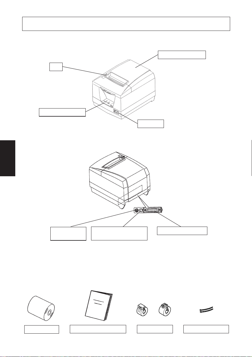
1. Parts Identification and Nomenclature
Printer cover
Lever
Pull this lever
in the
direction of
the arrow to
open the
printer cover.
Control panel
Features LED indicators to indicate printer
status and switches to
operate the printer.
Open this cover to
load or replace paper.
Switch
Used to turn on/off
power to the printer.
ENGLISH
Power connector
For connection of
the AC adapter.
Never unplug the
AC adapter while
the printer is on.
Roll paper
Peripheral drive connector
Connects to peripheral
units such as cash
drawers, etc.
Do not connect this to a
telephone.
User’s manual
– 1 –
Interface connector
For connection to a
host computer.
Ferrite Cores Fasteners
Page 6

Choosing a place for the printer
ENGLISH
Before actually unpacking the printer, you should take a few minutes to
think about where you plan to use it. Remember the following points
when doing this.
✓ Choose a firm, level surface where the printer will not be exposed to
vibration.
✓ The power outlet you plan to connect to for power should be nearby
and unobstructed.
✓ Make sure that the printer is close enough to your host computer for
you to connect the two.
✓ Make sure that the printer is not exposed to direct sunlight.
✓ Make sure that the printer is well away from heaters and other sources
of extreme heat.
✓ Make sure that the surrounding area is clean, dry, and free of dust.
✓ Make sure that the printer is connected to a reliable power outlet. It
should not be on the same electric circuit as copiers, refrigerators, or
other appliances that cause power spikes.
✓ Make sure that the room where you are using the printer is not too
humid.
– 2 –
Page 7

2. Consumable Parts and AC Adapter
When consumable parts have run out, use those specified in the table below.
Make sure that the AC adapter specified in the table is used.
Use of consumable parts or AC adapter which are not specified in the table may
result in damage to the printer, fire or electric shock.
Parts Name Specifications
Roll paper Thermal paper
Thickness: 0.06 to 0.08 mm
Width: 80 mm
Outer roll diameter: ø90 mm or less
Core outer diameter: ø18 mm
Core inner diameter: ø12 ±0.5 mm
Recommended paper (normal type paper)
Recommended paper (medium image stability paper)
Recommended paper (high image stability paper)
AC adapter (Option) Input: 100 to 240 V AC, 50-60 Hz
UP06021240 Output: 24 V DC±5 %, 2.5 A
0
- 1.0
+0.5
0
TF50KS-E2C (Nippon Paper Industries)
P220AG (Mitsubishi Paper Mills Limited)
PD-160R-N (Oji Paper Co., Ltd.)
AFP235 (Mitsubishi Paper Mills Limited)
ENGLISH
Important!
Access the following URL for the information of the recommended paper.
http://www.star-micronics.co.jp/
– 3 –
Page 8

3. Connecting Cables and AC Adapter
ENGLISH
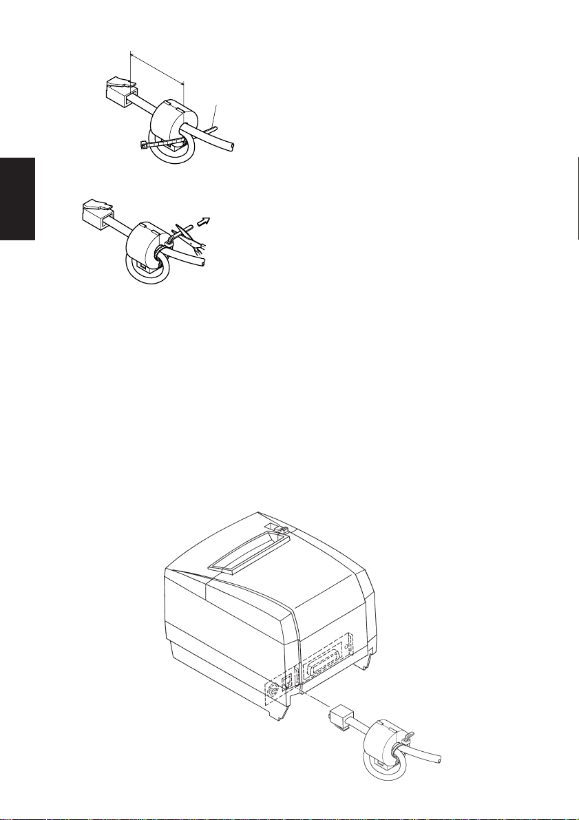
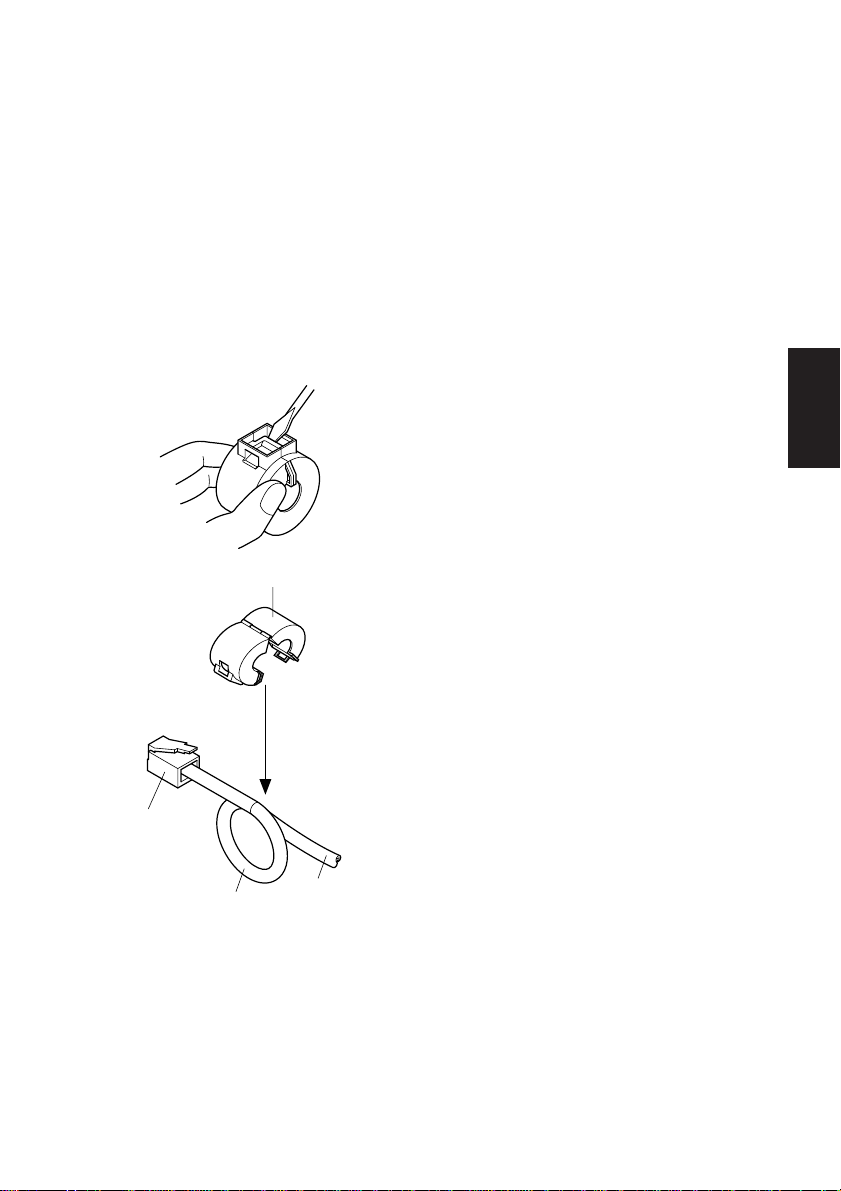
3-1. Interface Cable 3-1-1. Ferrite Core Installation
Ferrite core (27 mm wide)
Interface cable
(1)Affix the larger ferrite core onto the
cable as shown in the illustration
below.
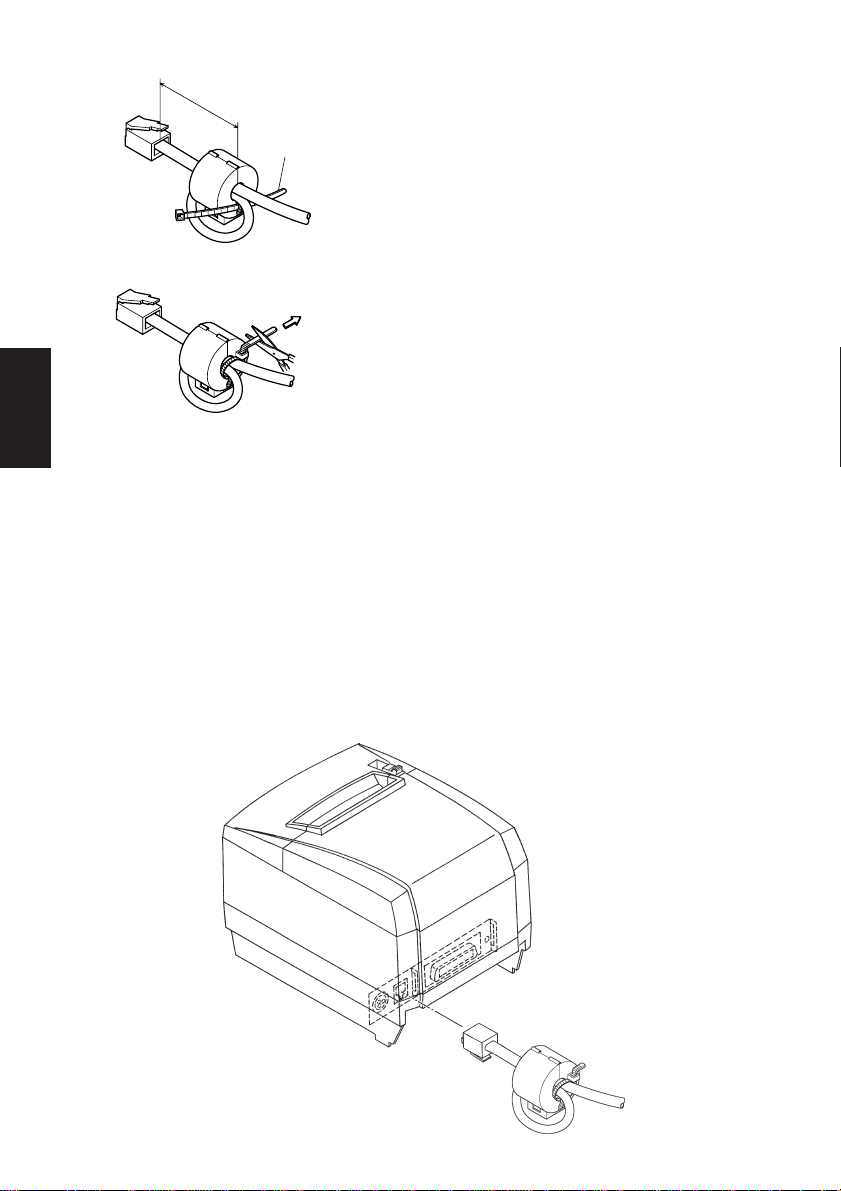
5 cm
maximum
Fastener
Pull and cut
(2)Pass the fastener through the ferrite
core.
(3)Loop the fastener around the cable
and lock it. Use scissors to cut off
any excess.
– 4 –
Page 9

3-1-2. Connecting the Interface Cable
Note: Before connecting/disconnecting the interface cable, make sure that
power to the printer and all the devices connected to the printer is
turned off. Also make sure the power cable plug is disconnected from
the AC outlet.
(1)Connect the interface cable to the connector on the rear panel of the printer.
(2)In the case of a serial interface, tighten the connector screws. In the case of a
parallel interface, fasten the connector clasps.
Serial interface cable
ENGLISH
– 5 –
Parallel interface cable
Page 10

3-2. Connecting to a Peripheral Unit
You can connect a peripheral unit to the printer using a modular plug. The
ENGLISH
following describes how to install the ferrite core and make the actual connection.
See “Modular plug” on page 98 for details about the type of modular plug that is
required. Note that this printer does not come with a modular plug or wire, so it
is up to you to obtain one that suits your needs.
Important!
Make sure that the printer is turned off and unplugged from the AC outlet and
that the computer is turned off before making connections.
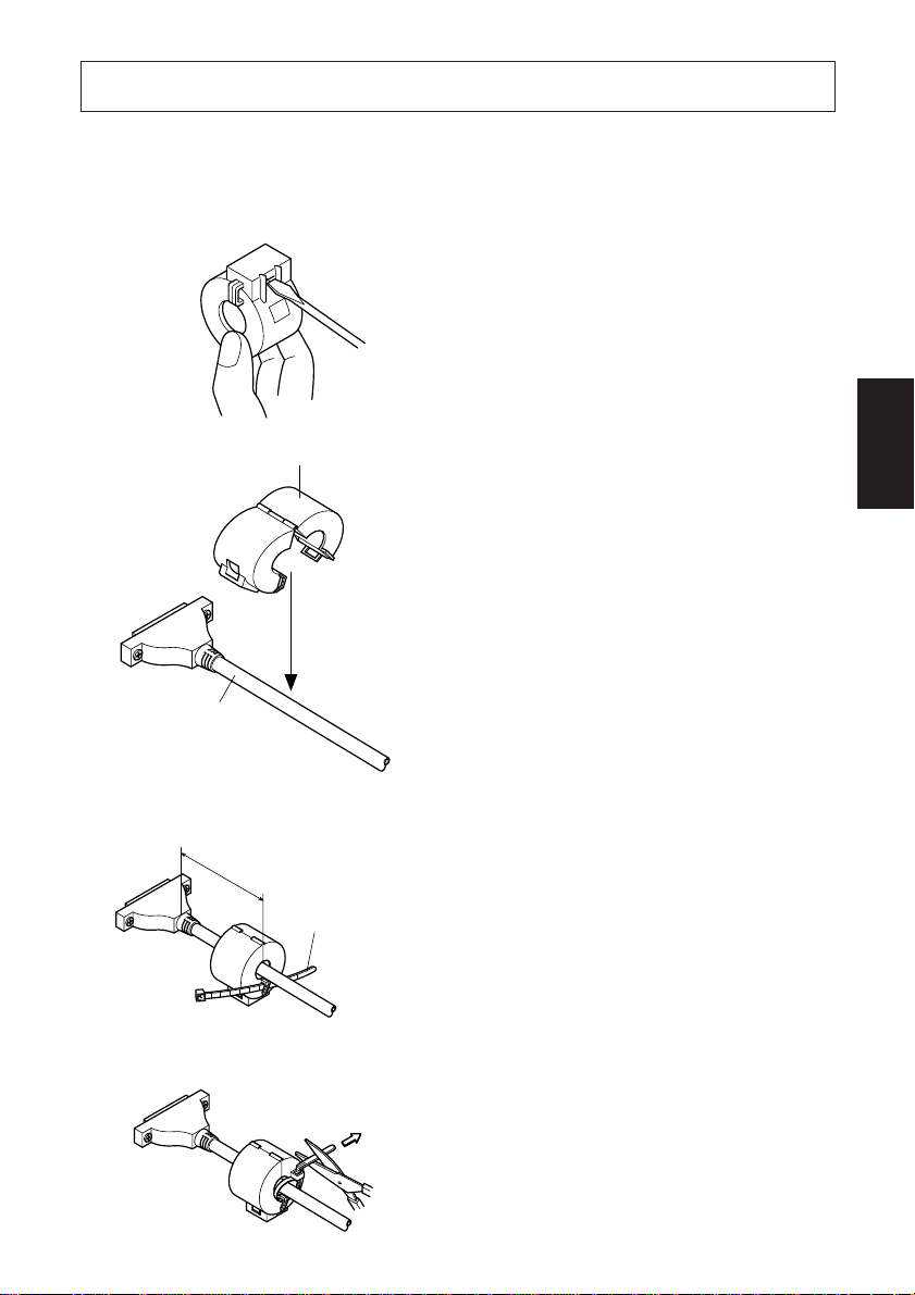
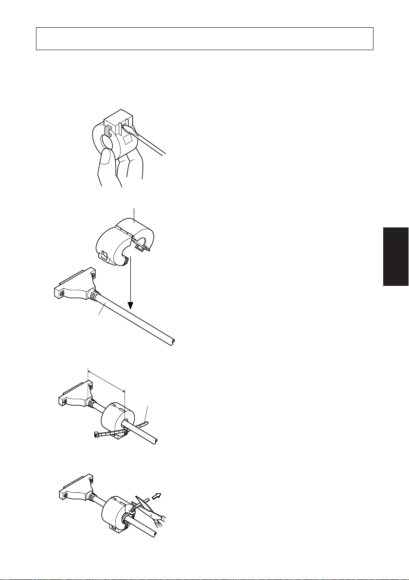
(1) Affix the smaller ferrite core onto
the modular wire as shown in the
illustration below.
Ferrite core (17.5 mm wide)
Connector
One loop
cable
– 6 –
Page 11

5 cm
maximum
Fastener
(2)Pass the fastener through the ferrite
core.
(3)Loop the fastener around the cable
Pull and cut
and lock it. Use scissors to cut off
any excess.
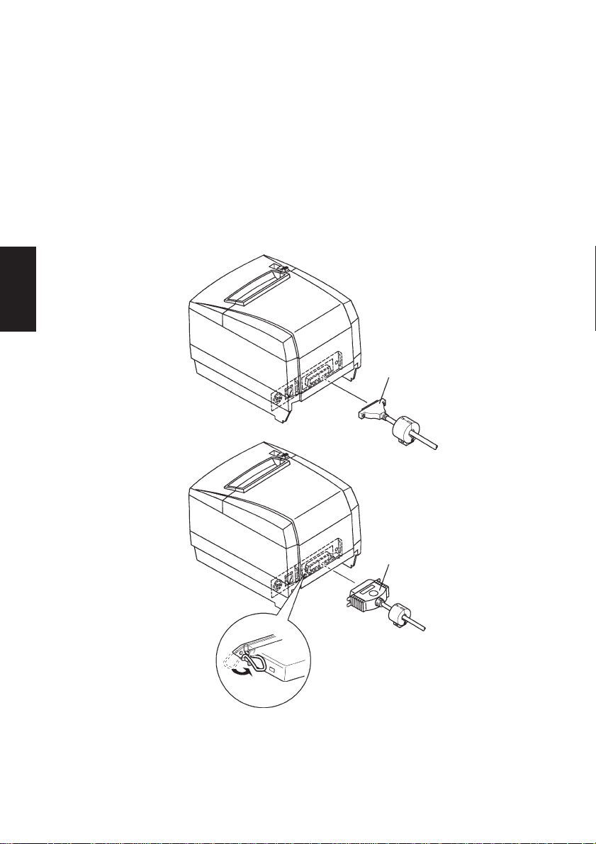
(4)Plug one end of the modular cable
into the modular jack of the peripheral.
(5)Remove the modular jack cover
from the back of the printer and plug
the other end of the modular cable
into the jack of the printer.
Note: Before connecting/disconnecting the peripheral drive cable, make
sure that power to the printer and all the devices connected to the
printer is turned off. Also make sure the power cable plug is disconnected from the AC outlet.
ENGLISH
(1)Connect the peripheral drive cable to the connector on the rear panel of the
printer.
– 7 –
Page 12

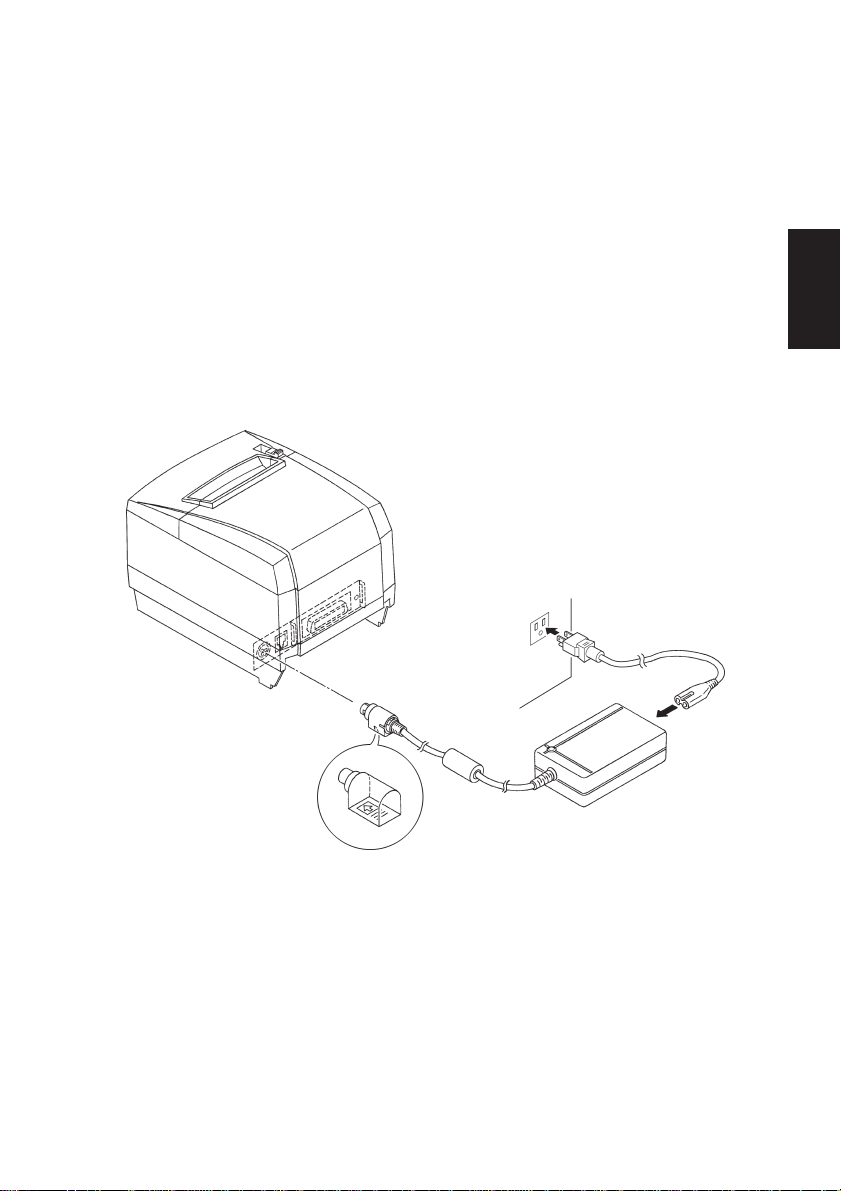
3-3. Connecting the Optional AC Adapter
ENGLISH
Note: Before connecting/disconnecting the AC adapter, make sure that
power to the printer and all the devices connected to the printer is
turned off. Also make sure the power cable plug is disconnected from
the AC outlet.
(1)Connect the AC adapter to the power cable.
Note: Use only the standard AC adapter and power cable.
(2)Connect AC adapter to the connector on the printer.
(3)Insert the power cable plug into an AC outlet.
– 8 –
Page 13

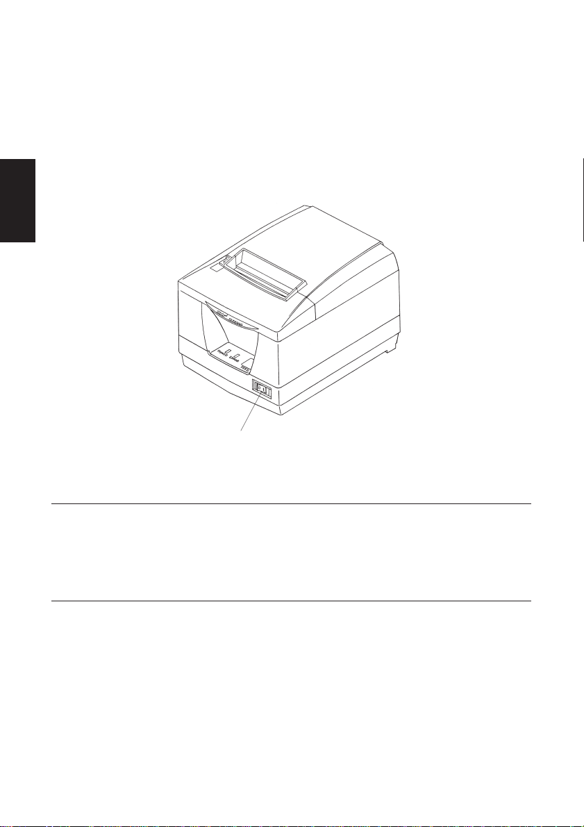
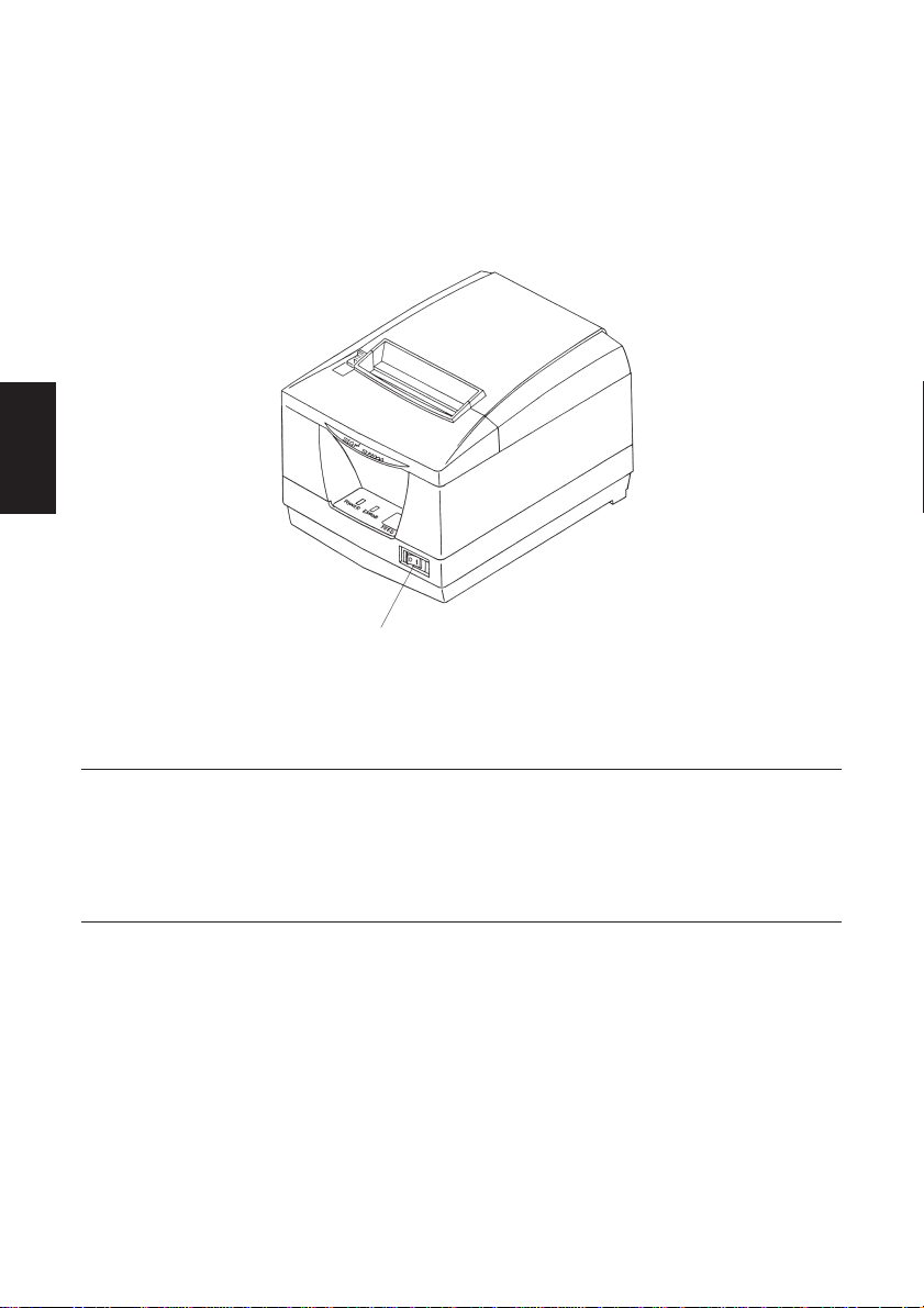
3-4. Turning Power On
Make sure that the AC adapter has been connected as described in 3-3.
(1)Set the power switch located on the front of the printer to on.
The POWER lamp on the control panel will light up.
Power switch
ENGLISH
Important!
We recommend that you unplug the printer from the power outlet
whenever you do not plan to use it for long periods. Because of this, you
should locate the printer so that the power outlet it is plugged into is
nearby and easy to access.
– 9 –
Page 14

4. Control Panel
ENGLISH
4-1. PAPER FEED Switch
Each time this switch is pressed, the paper feeds on line. When it is kept
depressed, the paper feeds continuously.
Note: This switch will be ineffective if no paper is loaded.
4-2. POWER LED (green LED)
This LED lights up when the power switch is set to on and power is supplied to
the printer.
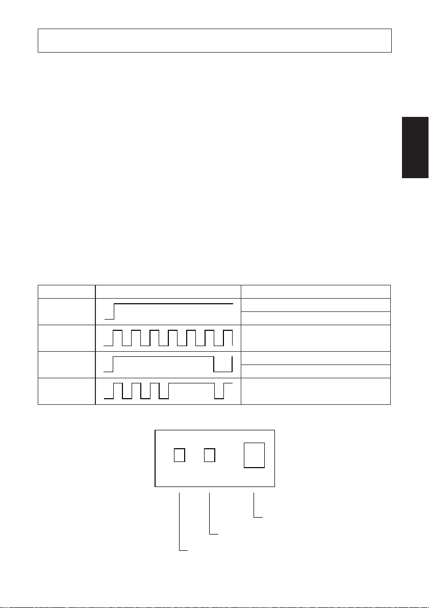
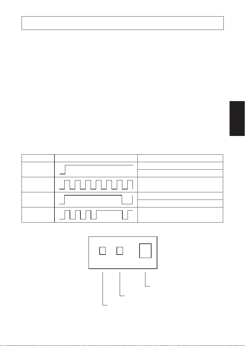
4-3. ERROR LED (red LED)
This LED lights up or blinks when any of the following errors occurs.
Error LED flashing pattern Error description
Light on Printer cover is open
Light flashing Paper has run out
Light on
Light flashing
Light on Abnormal head temperature (90°C)
Light flashing Malfunction in head connection
Light on
Light flashing
Paper is about to run out
Automatic cutter error
POWER ERROR FEED
Error LED (red)
Power LED (green)
– 10 –
Paper feed switch
Page 15

5. Loading Paper
5-1. Loading New Roll Paper
(1)Pull the lever toward you to open the printer cover.
Note: Make sure that the lever is pulled until it stops at the stopper. If the lever
is not pulled up to the stopper, the printer cover may not open.
(2)Peel the adhesive end off the paper.
Note: Make sure that the entire adhesive area is removed, since no printing
can be performed on that area.
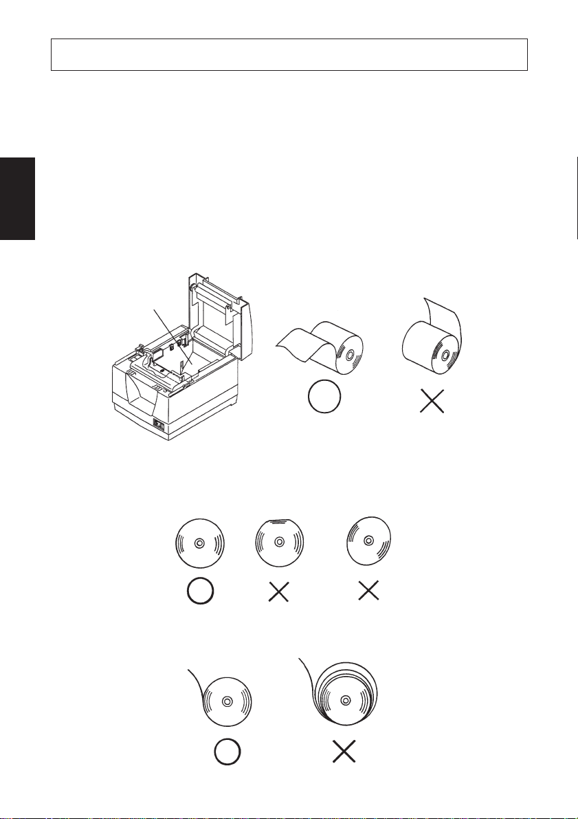
(3)Position the paper in the direction as shown below and place it into the paper
holder gently.
Paper holder
ENGLISH
Note 1: Make sure that the paper is not deformed. If a roll paper like those
shown below is used, a malfunction may result.
Note 2: If the paper sags as shown below after it has been loaded into the
paper holder, make the paper taut.
– 11 –
Page 16

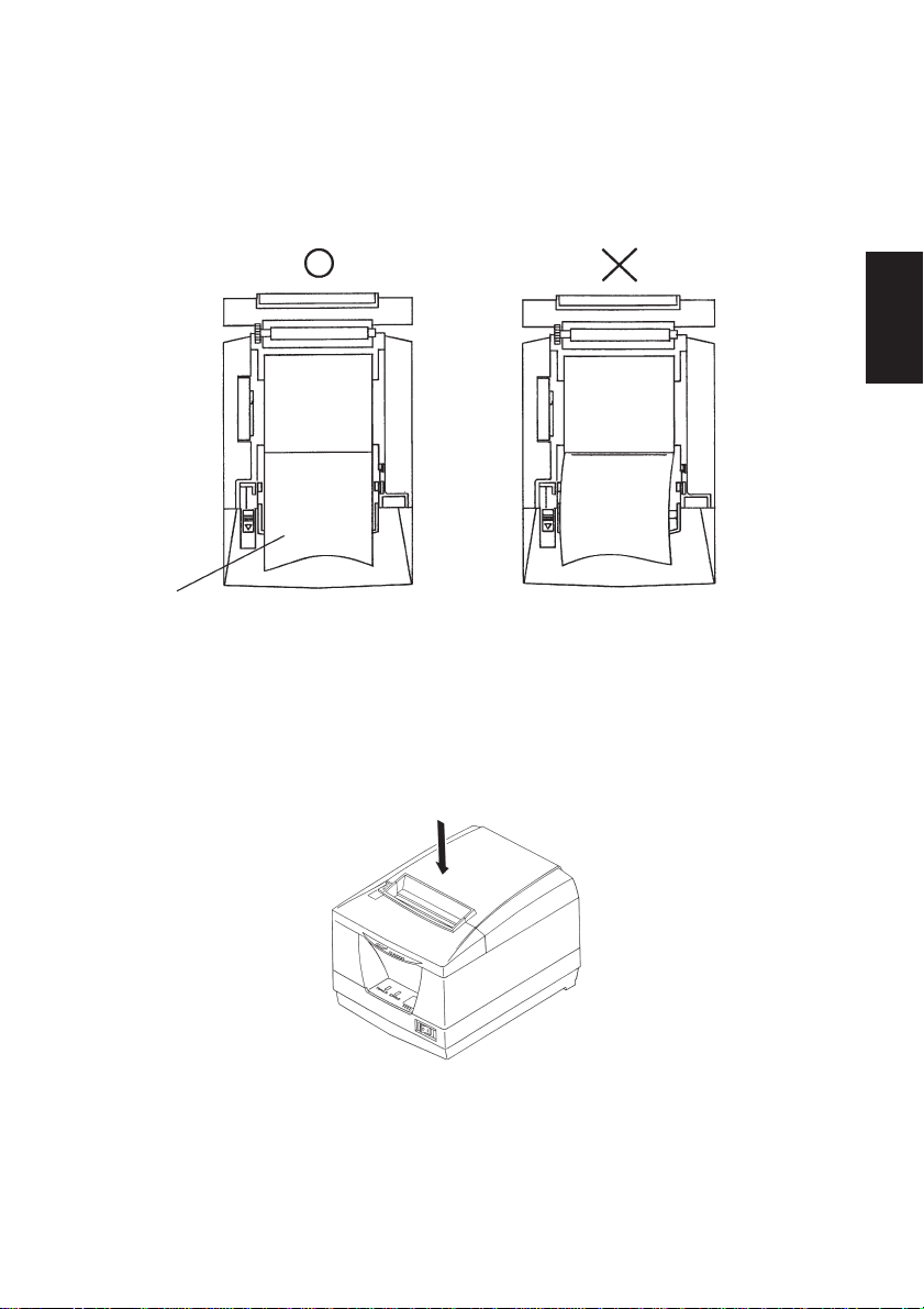
(4)Make sure that the paper is positioned straight, then close the printer cover
gently.
ENGLISH
Note 1: Make sure that the paper is positioned straight. If the printer cover
is closed with the paper skewed as shown below, a paper jam may
result.
Paper
Note 2: Lock the printer cover by pressing on the center of the cover
(indicated by an arrow in the figure below). If any part of the cover
other than the center is pressed, the cover may not be locked
properly. This may sometimes disables printing.
– 12 –
Page 17

(5)If the power switch is set to OFF, set it to ON to turn on the printer. Make sure
that the ERROR LED is not lit.
Note: While the ERROR LED is lit, the printer will not accept any commands
such as the print command, so make sure that the printer cover is locked
properly.
(6)Once the printer cover is locked, the paper end will be ejected and the end cut
off automatically.
5-2. Removing Remaining Paper
(1)Pull the lever toward you to open the printer cover.
Note: Make sure that the lever is pulled until it stops at the stopper. If the lever
is not pulled up to the stopper, the printer cover may not open.
(2)Remove the remaining paper.
ENGLISH
– 13 –
Page 18

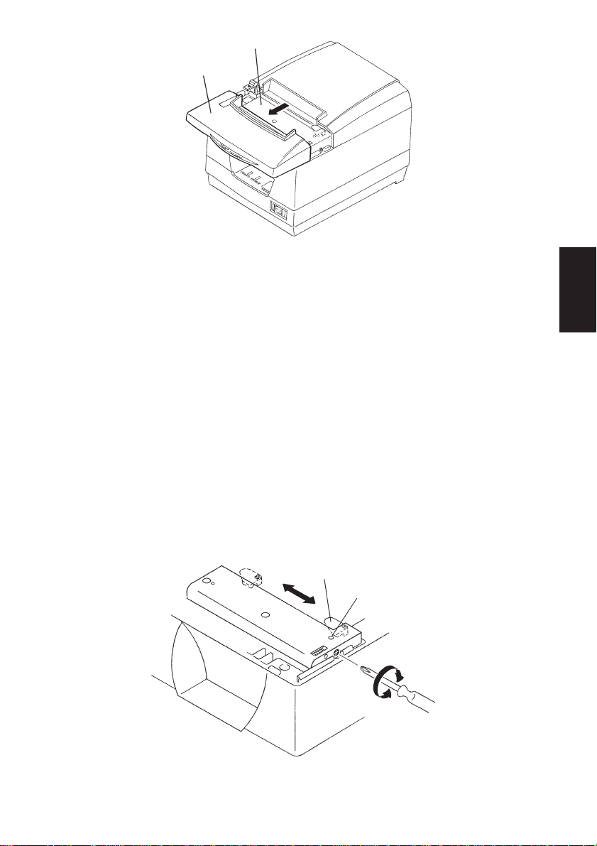
6. Near-end Sensor
ENGLISH
This printer is equipped with a sensor that detects when a roll of paper is near the
end. Read the following if you are going to use this sensor.
(1)Pull the lever in the direction indicated on it, and then open the printer cover.
(2)Loosen the two sensor fixing screws.
(3)Slide the sensor unit up or down, and then adequately tighten its screws.
The following table shows the diameter of the paper that would remain on the
roll in order for the sensor, installed at the specified sensor fixing screw
position, to detect it.
Sensor fixing screws
(Level 1)
ø18 mm
ø12 mm
Roll paper core
A
A
– 14 –
Page 19

(4)Insert the paper roll, and check that the sensor correctly detects that the paper
roll is about to run out.
Error LED LED goes out when there is paper.
LED flashes when the paper is about to run out.
Diameter of remaining paper A Screw position
Approx. ø22 mm Level 1 (bottom)
Approx. ø26 mm Level 2 (top)
Cautions
1) The factory setting is level 1.
2) Always use a paper roll with a core that has an inside diameter of 12 mm and
an outside diameter of 18 mm in order to ensure proper detection of the
remaining paper amount.
ENGLISH
– 15 –
Page 20

7. Preventing and Clearing Paper Jams
ENGLISH
7-1. Preventing Paper Jams
The paper should not be touched during ejection and before it is cut.
Pressing or pulling the paper during ejection may cause a paper jam, paper cutting
failure or line feed failure. Do not open the printer cover during cutting.
7-2. Removing Paper Jam
If a paper jam occurs, clear it as described below.
(1)Set the power switch to off to turn off power to the printer.
(2)Pull the lever toward you to open the printer cover.
Note: Make sure that the lever is pulled until it stops at the stopper. If the lever
is not pulled up to the stopper, the printer cover may not open.
(3)Remove the jammed paper.
Note: Take care not to damage the printer when removing the jammed paper.
Since it is easy to damage the thermal head in particular, take care not
to touch it.
– 16 –
Page 21

(4)Position the roll paper straight and close the printer cover gently.
Note 1: Make sure that the paper is positioned straight. If the printer cover
is closed with the paper skewed, a paper jam may result.
Note 2: Lock the printer cover by pressing on the center of the cover. If any
part of the cover other than the center is pressed, the cover may not
be locked properly. This may sometimes disable printing.
(5)Set the power switch to on to turn on power to the printer. Make sure that the
ERROR LED is not lit.
Note: While the ERROR LED is lit, the printer will not accept any commands
such as the print command, so make sure that the printer cover is locked
properly.
7-3. Releasing a Locked Cutter
If the auto cutter locks up or fails to cut the paper, follow the steps below.
Caution
Since working on the cutter may be dangerous, be sure to turn off the printer first.
(1)Set the power switch to OFF to turn off the printer.
(2)Slide off the front cover to reveal the auto cutter.
ENGLISH
(3)Remove any jammed paper.
Note: Be careful not to damage the printer while removing any jammed
paper.
Since the thermal print head is particularly sensitive, be sure not to
touch it.
Auto cutter
Front cover
– 17 –
Page 22

(4)If the cutter’s moving blade is protruding, use a Phillips screwdriver to turn
the Phillip-head screw and return the moving blade to its home position.
ENGLISH
When the check window is completely white, the moving blade is at its home
position.
Note 1: Do not apply extreme pressure to the moving blade.
Note 2: If the moving blade is protruding too much, the printer cover cannot
be opened. Trying to open the printer cover may damage the cutter.
(5) Open the printer cover, remove any jammed paper, and then re-install the
paper roll.
(6)Install the front cover, and then set the power switch to ON.
Moving blade
Check window
– 18 –
Page 23

8. Test Print Method
8-1. Producing a Test Print
To start test print, set the power switch to off, set the paper in place, then set the
power switch to on while holding down the FEED switch. Release the switch
within three seconds.
When a certain amount of printing is performed, the printer will cut the paper and
stop automatically.
8-2. Hexadecimal Dump
This prints data sent from the host in hexadecimal format and in the corresponding ASCII characters. This is useful for debugging applications and for analyzing
scrambled characters.
Starting and stopping Hex Dump printing
While holding down the Feed switch, turn the power on. Hold down the switch
for five seconds; Hex Dump will begin operation when the switch is released.
If the switch is released within three seconds, the Self Test will run.
Stop Hex Dump by turning the power off.
The received data is printed as follows.
ENGLISH
Address Hexadecimal data ASCII data
– 19 –
Page 24

9. Periodical Cleaning
ENGLISH
Printed characters may become partially unclear due to accumulated paper dust
and dirt. To prevent such a problem, paper dust collected in the paper holder and
paper transport section and on the surface of the thermal head must be removed
periodically. Such cleaning is recommended to be carried out once a month.
9-1. Cleaning the Thermal Head
To remove blackish dust collected on the surface of the thermal head, wipe it with
alcohol (IPA).
Note: The thermal head is easy to damage, so clean it gently with a soft cloth.
Take sufficient care not to scratch it when cleaning it.
9-2. Cleaning the Paper Holder
Use a soft cloth to remove paper dust from the paper holder and paper transport
section.
– 20 –
Page 25

TABLE DES MATIERES
1. Identification des pièces et nomenclature....................................................22
2. Consommables et adaptateur secteur ..........................................................24
3. Câbles de connexion et adaptateur secteur .................................................25
3-1. Câble d’interface ..................................................................................25
3-2. Raccordement d’un appareil périphérique ...........................................27
3-3. Connexion de l’adaptateur secteur optionnel.......................................29
3-4. Mise sous tension de l’imprimante ......................................................30
4. Panneau des commandes ..............................................................................31
4-1. Touche d’avance de papier PAPER FEED ..........................................31
4-2. DEL d’alimentation POWER (DEL verte) ..........................................31
4-3. DEL d’erreur ERROR (DEL rouge) ....................................................31
5. Chargement du papier ..................................................................................32
5-1. Chargement d’un rouleau de papier neuf .............................................32
5-2. Retrait du papier...................................................................................34
6. Capteur de fin de rouleau .............................................................................35
7. Prévention et correction de bourrages de papier .......................................37
7-1. Prévention des bourrages de papier .....................................................37
7-2. Correction de bourrages de papier .......................................................37
7-3. Libération d’une unité de découpage bloquée .....................................38
8. Test d’impression...........................................................................................40
8-1. Exécution d’un test d’impression.........................................................40
8-2. Vidage hexadécimal .............................................................................40
9. Nettoyage ........................................................................................................41
9-1. Nettoyage de la tête d’impression ........................................................41
9-2. Nettoyage du support de papier ...........................................................41
APPENDICE......................................................................................................87
FRANÇAIS
L’appendice n’est pas traduit.
Pour obtenir la dernière version de ce manuel, consultez l’adresse URL suivante:
http:/www.star-micronics.co.jp/service/sp_sup_e.htm.
– 21 –
Page 26

FRANÇAIS
1. Identification des pièces et nomenclature
Capot de
l’imprimante
Levier
Tirez ce levier
dans le sens de
la flèche pour
ouvrir le capot de
l’imprimante.
Panneau des commandes
Le panneau est équipé de
commutateurs permettant la
commande de l’imprimante et
de DELs indiquant les statuts.
Interrupteur
Permet la mise sous et
hors tension de
l’appareil.
Ouvrez ce capot
pour charger ou
remplacer le
papier.
Connecteur
d’alimentation
Ce connecteur
vous permet de
connecter le câble
de l’adaptateur
secteur. Ne
déconnectez pas
le câble lorsque
l’imprimante est
sous tension.
Rouleau de papier Mode d’emploi
Connecteur d’appareil
périphérique
Ce connecteur vous
permet de raccorder
l’imprimante à des
appareils périphériques
tels que des tiroirscaisses, etc.
Ne pas raccorder à un
téléphone.
Connecteur
d’interface
Ce connecteur
vous permet de
connecter
l’imprimante à
l’ordinateur-hôte.
Tore de ferrite Attache
– 22 –
Page 27

Emplacement de l’imprimante
Avant de déballer l’imprimante, déterminez l’emplacement où vous
souhaitez l’installer. Veuillez observer les points ci-dessous lors de votre
choix.
✓ Choisissez une surface stable et de niveau sur laquelle l’imprimante
ne sera exposée à aucune vibration.
✓ Assurez-vous que l’emplacement dispose d’une prise secteur proche
et d’accès aisé.
✓ Assurez-vous que la distance entre l’imprimante et l’ordinateur-hôte
vous permet de les raccorder aisément.
✓ Assurez-vous que l’imprimante n’est pas exposée directement aux
rayons du soleil.
✓ Tenez l’imprimante à l’écart des sources de chaleur importante, telles
que les appareils de chauffage, etc.
✓ Assurez-vous que le lieu où vous souhaitez installer l'imprimante est
propre, sec et n'est pas poussiéreux.
✓ Assurez-vous que la prise secteur à laquelle vous raccordez l’impri-
mante délivre une tension stable. Evitez de raccorder l’imprimante à
la prise secteur d’un circuit alimentant de gros consommateurs de
courant, tels qu’un photocopieur, réfigérateur, etc.
✓ Assurez-vous que le lieu où vous installez l’imprimante n’est pas
excessivement humide.
FRANÇAIS
– 23 –
Page 28

2. Consommables et adaptateur secteur
Il convient d’utiliser exclusivement les types de papier figurant dans le tableau
ci-dessous. Veillez également à utiliser l’adaptateur secteur qui figure dans le
tableau.
L’utilisation d’un type de papier et d’adaptateur ne figurant pas dans le tableau
FRANÇAIS
risque d’endommager l’imprimante, de causer un incendie ou une décharge
électrique.
Nom de pièce Caractéristiques
Rouleau de papier Papier thermique
Épaisseur: 0,06 à 0,08 mm
Largeur: 80 mm
Diamètre extérieur du rouleau : ø90 mm ou moins
Diamètre extérieur du support de rouleau : ø18 mm
Diamètre intérieur du support de rouleau : ø12 ±0,5 mm
Papier conseillé (pour impression thermique normale)
Papier conseillé (pour stockage de durée moyenne)
Papier conseillé (pour stockage de longue durée)
Adaptateur secteur (optionnel) Entrée: 100 à 240 V CA, 50-60 Hz
UP06021240 Sortie: 24 V CC±5 %, 2,5 A
0
- 1,0
TF50KS-E2C (Nippon Paper Industries)
P220AG (Mitsubishi Paper Mills Limited)
PD-160R-N (Oji Paper Co., Ltd.)
AFP235 (Mitsubishi Paper Mills Limited)
+0,5
0
Attention!
Pour obtenir des informations concernant le papier recommandé, consultez l’adresse URL suivante : http://www.star-micronics.co.jp/.
– 24 –
Page 29

3. Câbles de connexion et adaptateur secteur
3-1. Câble d’interface 3-1-1. Installation du tore de ferrite
(1)Fixez la grande gaine en ferrite sur
le câble comme illustré.
Tore de ferrite (27 mm de largeur)
Interface câble
FRANÇAIS
5 cm
maximum
Tirez et coupez
(2)Passez l’attache dans le tore de fer-
rite.
Attache
(3) Passez l’attache autour du tore de
ferrite et serrez-la. Coupez l’extrémité de l’attache à l’aide de ciseaux.
– 25 –
Page 30

3-1-2. Connexion du câble d’interface
Remarque:Avant de connecter ou déconnecter le câble d’interface, veillez à
ce que l’imprimante et tous les appareils qui y sont connectés
soient hors tension. Veillez également à débrancher le câble
d’alimentation de la prise secteur.
FRANÇAIS
(1)Connectez le câble d’interface à la borne figurant sur le panneau arrière de
l’imprimante.
(2)Dans le cas d’une interface série, resserrez les vis du connecteur. Dans le cas
d’une interface parallèle, fixez le connecteur avec les fermoirs.
Câble d’interface série
– 26 –
Câble d’interface parallèle
Page 31

3-2. Raccordement d’un appareil périphérique
Vous pouvez raccorder un appareil périphérique à l’imprimante à l’aide d’une
fiche modulaire. Nous expliquons ci-dessous comment installer le tore de ferrite
et faire le raccordement proprement dit. Pour les détails sur le type de fiche
modulaire à utiliser, reportez-vous à la page 98. Notez que le fil ou la fiche
modulaires ne sont pas fournis avec l’imprimante. Vous devrez donc vous les
procurer.
Attention!
Assurez-vous que l’imprimante est hors tension, qu’elle est débranchée de la
prise secteur et que l’ordinateur est hors tension avant d’effectuer les connexions.
(1)Fixez la petite gaine en ferrite sur le
câble modulaire comme illustré cidessous.
Tore de ferrite (17,5 mm de largeur)
FRANÇAIS
Connecteur
Une boucle
Câble
– 27 –
Page 32
FRANÇAIS
Remarque:Avant de connecter ou déconnecter le câble du pilote de périphé-
5 cm
maximum
Attache
(2)Passez l’attache dans le tore de fer-
rite.
(3) Passez l’attache autour du tore de
Tirez et coupez
ferrite et serrez-la. Coupez l’extrémité de l’attache à l’aide de ciseaux.
(4) Raccordez une extrémité du câble
modulaire à la prise modulaire du
périphérique.
(5)Retirez le cache de prise modulaire
au dos de l’imprimante, et raccordez l’autre extrémité du câble modulaire dans la prise de l’imprimante.
rique, veillez à ce que l’imprimante et tous les appareils qui y sont
connectés soient hors tension. Veillez également à débrancher le
câble d’alimentation de la prise secteur.
(1)Connectez le câble de pilote de périphérique à la borne figurant sur le panneau
arrière de l’imprimante.
– 28 –
Page 33
3-3. Connexion de l’adaptateur secteur optionnel
Remarque:Avant de connecter ou déconnecter l’adaptateur secteur, veillez
à ce que l’imprimante et tous les appareils qui y sont connectés
soient hors tension. Veillez également à débrancher le câble
d’alimentation de la prise secteur.
(1)Connectez l’adaptateur secteur au câble d’alimentation.
Remarque:Utilisez exclusivement l’adaptateur secteur et le câble d’alimen-
tation destinés à l’imprimante.
(2)Connectez l’adaptateur secteur à la borne de l’imprimante.
(3)Branchez la prise du câble d’alimentation à la prise secteur.
FRANÇAIS
– 29 –
Page 34
3-4. Mise sous tension de l’imprimante
Assurez-vous d’avoir bien connecté l’adaptateur secteur comme décrit à la
section 3-3.
(1)Placez l’interrupteur d’alimentation, situé à l’avant de l’imprimante, sur la
position sous tension.
FRANÇAIS
La DEL POWER s’allume au panneau des commandes.
Interrupteur
d’alimentation
Attention!
Nous vous recommandons de débrancher l’imprimarte du secteur lorsque vous ne comptez pas l’utiliser pendant une période prolongée. Par
ailleurs, veillez lors de l’installation à ce que la prise secteur alimentant
l’imprimante soit proche et d’accès facile.
– 30 –
Page 35
4. Panneau des commandes
4-1. Touche d’avance de papier PAPER FEED
Le papier avance d’une ligne à chaque pression sur cette touche. Une pression
continue sur la touche fera avancer le papier de façon continue.
Remarque:Une pression sur cette touche n’a d’effet que si du papier est
chargé dans l’imprimante.
4-2. DEL d’alimentation POWER (DEL verte)
Cette DEL s’allume lorsque l’interrupteur d’alimentation est placé sur hors
tension et que l’appareil est alimenté par le secteur.
4-3. DEL d’erreur ERROR (DEL rouge)
Cette DEL s’allume ou clignote lorsqu’une des erreurs énumérées ci-dessous se
produit.
Mode d’éclairage de la DEL d’erreur Description de l’erreur
Allumée Capot d’imprimante ouvert
Clignotante Papier épuisé
Allumée
Clignotante
Allumée
Clignotante
Allumée
Clignotante
Le papier est presque épuisé
Température anormale de la tête d’imprimante (90°C)
Dysfonctionnement dans la connexion de la tête
Erreur de l’unité de découpage automatique
FRANÇAIS
POWER ERROR FEED
DEL d’erreur (rouge)
DEL d’alimentation (verte)
– 31 –
Touche d’avance de papier
Page 36
5. Chargement du papier
5-1. Chargement d’un rouleau de papier neuf
(1)Tirez le levier vers le bas afin d’ouvrir le capot de l’imprimante.
Remarque:Veillez à tirer le levier tout à fait jusqu’à sa butée. Si le levier n’est
FRANÇAIS
(2)Retirez l’adhésif de l’extrémité du papier.
Remarque:Veillez à bien retirer l’intégralité de l’adhésif. En effet, l’impres-
(3)Placez le papier dans la direction indiquée ci-dessous et insérez-le avec soin
dans le support du papier.
Support du papier
pas tiré tout à fait, le capot pourrait ne pas s’ouvrir.
sion ne peut s’effectuer sur celui-ci.
Remarque 1: Veillez à ce que le rouleau de papier soit en bon état. Si le
rouleau est déformé comme illustré ci-dessous, des problèmes risquent de survenir.
Remarque 2: Si le papier se déroule comme illustré ci-dessous après son
chargement dans le support de papier, il convient de le
tendre.
– 32 –
Page 37
(4)Veillez à ce que le papier soit placé bien droit, puis refermez doucement le
capot de l’imprimante.
Remarque 1: Le papier doit être placé bien droit. Si vous refermez le capot
de l’imprimante alors que le papier est de travers (voir
illustration), un bourrage peut se produire.
Papier
Remarque 2: Verrouillez le cache de l’imprimante en appuyant à l’endroit
du capot repéré par la flèche dans l’illustration ci-dessous. Si
vous appuyez à tout autre endroit, le capot risque de ne pas
être verrouillé, ce qui pourrait empêcher l’impression.
FRANÇAIS
– 33 –
Page 38

(5)Si l’interrupteur d’alimentation est sur la position hors tension OFF, réglez-
le sur la position sous tension ON pour mettre l’imprimante sous tension.
Assurez-vous que la DEL ERROR n’est pas allumée.
Remarque:Tant que la DEL ERROR est allumée, l’imprimante n’accepte
aucune commande. Il faut donc veiller à ce que le capot de
l’imprimante soit verrouillé.
FRANÇAIS
(6)Une fois que le capot d’imprimante est verrouillé, l’extrémité du papier sera
éjectée et coupée automatiquement.
5-2. Retrait du papier
(1)Tirez le levier vers le bas afin d’ouvrir le capot de l’imprimante.
Remarque:Veillez à tirer le levier tout à fait jusqu’à sa butée. Si le levier n’est
pas tiré tout à fait, le capot pourrait ne pas s’ouvrir.
(2)Retirez le papier.
– 34 –
Page 39

6. Capteur de fin de rouleau
Cette imprimante est équipée d’un capteur détectant l’approche de la fin de
rouleau. Pour savoir comment utiliser cette fonction, lire les instructions cidessous.
(1) Tirez sur le levier dans le sens indiqué dessus, puis ouvrez le capot de
l’imprimante.
(2)Desserrez les deux vis de montage du capteur.
(3)Faites glisser le capteur vers le haut ou vers le bas, puis serrez correctement
ses vis.
Le tableau suivant indique le diamètre du papier devant rester sur le rouleau
afin que le capteur installé dans la position spécifiée de la vis de montage du
capteur puisse le détecter.
FRANÇAIS
Vis de montage du capteur
(Cran 1)
ø18 mm
ø12 mm
Mandrin du rouleau
de papier
A
A
– 35 –
Page 40

(4)Insérez le rouleau de papier, puis vérifiez que le capteur identifie correctement
le moment où le papier va être épuisé.
DEL d’erreur La DEL s’éteint quand il y a du papier.
La DEL clignote quand le papier va être épuisé.
Diamètre du papier restant A Position de la vis
FRANÇAIS
Environ ø22 mm Cran 1 (bas)
Environ ø26 mm Cran 2 (haut)
Attention
1) Le capteur de fin de rouleau est positionné sur le cran 1 à la sortie d’usine.
2) Afin d’assurer une détection correcte de la quantité de papier restant sur le
rouleau, toujours employer un rouleau de papier dont les diamètres interne et
externe du rouleau de carton correspondent respectivement à 12 mm et 18 mm.
– 36 –
Page 41

7. Prévention et correction de bourrages de papier
7-1. Prévention des bourrages de papier
Il convient de ne jamais toucher le papier pendant son éjection et avant qu’il soit
coupé. Appuyer ou tirer sur le papier pendant son éjection risque de provoquer
un bourrage, des problèmes de coupure ou d’avance de ligne. Ne pas ouvrir le
capot d’imprimante pendant la coupure.
FRANÇAIS
7-2. Correction de bourrages de papier
En cas de bourrage de papier, procédez comme suit afin d’y remédier :
(1)Mettez l’appareil hors tension.
(2)Tirez le levier tout à fait vers le bas afin d’ouvrir le capot de l’imprimante.
Remarque:Veillez à tirer le levier jusqu’à sa butée. Si le levier n’est pas tiré
tout à fait, le capot pourrait ne pas s’ouvrir.
(3)Retirez le papier bloqué.
Remarque:Veillez à ne pas endommager l’imprimante lors du retrait du
papier bloqué.
Veillez particulièrement à ne pas toucher la tête d’impression
thermique en raison de sa fragilité.
– 37 –
Page 42

(4)Veillez à insérer le rouleau de papier tout droit et refermez avec soin le capot
de l’imprimante.
Remarque 1: Le papier doit être placé bien droit. Si vous refermez le capot
de l’imprimante alors que le papier est de travers (voir
illustration), un bourrage peut se produire.
Remarque 2: Verrouillez le cache de l’imprimante en appuyant à l’endroit
FRANÇAIS
du capot repéré par la flèche dans l’illustration ci-dessous. Si
vous appuyez à tout autre endroit, le capot risque de ne pas
être verrouillé, ce qui pourrait empêcher l’impression.
(5)Mettez l’imprimante sous tension. Assurez-vous que la DEL ERROR n’est
pas allumée.
Remarque:Tant que la DEL ERROR est allumée, l’imprimante n’accepte
aucune commande. Il faut donc veiller à ce que le capot de
l’imprimante soit verrouillé.
7-3. Libération d’une unité de découpage bloquée
Si l’unité de découpage automatique se bloque ou ne coupe pas le papier, suivez
les étapes ci-dessous.
Attention
Le travail sur l’unité de découpage étant dangereux, n’oubliez pas de mettre
avant tout l’imprimante hors tension.
(1)Réglez l’interrupteur d’alimentation sur la position hors tension OFF pour
mettre l’imprimante hors tension.
(2)Faites glisser le couvercle avant pour dégager l’unité de découpage automa-
tique.
(3)Enlevez le papier coincé.
Remarque:Faites attention à ne pas endommager l’imprimante pendant que
vous enlevez le papier coincé.
La tête d’impression thermique étant particulièrement sensible,
veillez à ne pas la toucher.
– 38 –
Page 43

Unité de découpage
automatique
Couvercle avant
(4) Si la lame mobile de l’unité de découpage dépasse, utilisez un tournevis
cruciforme pour tourner la vis cruciforme et ramener la lame dans sa position
d’origine.
Quand la fenêtre de contrôle est complètement blanche, la lame mobile est
dans sa position d’origine.
Remarque 1: N’appliquez pas de pression excessive sur la lame mobile.
Remarque 2: Si la lame mobile dépasse trop, le capot de l’imprimante ne
pourra pas être ouvert. Vous risquez d’endommager l’unité
de découpage automatique en essayant d’ouvrir le capot de
l’imprimante.
FRANÇAIS
(5)Ouvrez le capot de l’imprimante, enlevez le papier coincé, puis remettez le
rouleau de papier en place.
(6)Installez le couvercle avant, puis réglez l’interrupteur d’alimentation sur la
position sous tension.
Lame mobile
Fenêtre de contrôle
– 39 –
Page 44

8. Test d’impression
8-1. Exécution d’un test d’impression
Avant d’effectuer un test d’impression, commencez par mettre l’imprimante hors
tension, insérez le papier, puis remettez l’imprimante sous tension tout en
maintenant la touche d’avance FEED enfoncée. Relâchez la pression sur la
FRANÇAIS
touche dans les trois secondes qui suivent.
Après avoir imprimé pendant un certain temps, l’imprimante coupe le papier et
s’arrête automatiquement.
8-2. Vidage hexadécimal
Cette commande entraîne l’impression des données envoyées par l’hôte dans le
format hexadécimal et dans les caractères ASCII correspondants. Cette fonction est
pratique pour le débogage des applications et l’analyse des caractères embrouillés.
Lancement et arrêt de l’impression de vidage hexadécimal
Tout en maintenant la touche d’avance de papier enfoncée, mettez l’appareil
sous tension. Maintenez la touche enfoncée pendant cinq secondes ; le vidage
hexadécimal commencera quand vous relâcherez la pression sur la touche. Si
vous relâchez la pression sur la touche dans les trois secondes, l’autotest
commencera.
Arrêtez le vidage hexadécimal en mettant l’appareil hors tension.
Les données reçues sont imprimées comme suit :
Adresse
Données hexadécimales Données ASCII
– 40 –
Page 45

9. Nettoyage
Les caractères imprimés pourraient devenir partiellement illisibles en raison de
l’accumulation de la poussière de papier et de crasse. Afin de prévenir ce genre
de problème, il convient de nettoyer régulièrement la poussière qui s’accumule
sur le support de papier, les passages du papier et la surface de la tête d’impression. Il est recommandé d’effectuer ce nettoyage une fois par mois.
9-1. Nettoyage de la tête d’impression
Nettoyez la poussière noirâtre accumulée sur la surface de la tête d’impression à
l’alcool isopropylique.
Remarque:La tête d’impression thermique est fragile, il convient donc de
procéder avec précaution. Prenez soin de ne pas la griffer.
9-2. Nettoyage du support de papier
Nettoyez la poussière de papier accumulée sur le support de papier et sur les
passages du papier à l’aide d’un chiffon doux.
FRANÇAIS
– 41 –
Page 46

FRANÇAIS
– 42 –
Page 47

INHALTSVERZEICHNIS
1. Beschreibung und Bezeichnung der Geräteteile.........................................44
2. Verbrauchsteile und Netzteil ........................................................................46
3. Anschlußkabel und Netzteil..........................................................................47
3-1. Schnittstellenkabel ...............................................................................47
3-2. Anschluß an ein Peripheriegerät ..........................................................49
3-3. Anschließen des optionalen Netzteils ..................................................51
3-4. Einschalten ...........................................................................................52
4. Bedienfeld .......................................................................................................53
4-1. Papiereinzugknopf (PAPER FEED) ....................................................53
4-2. Netz-LED (POWER) (grüne LED)......................................................53
4-3. Fehler-LED (ERROR) (rote LED).......................................................53
5. Einlegen von Papier.......................................................................................54
5-1. Einlegen einer neuen Papierrolle .........................................................54
5-2. Entfernen des restlichen Papiers ..........................................................56
6. Papiervorrat-Sensor ......................................................................................57
7. Verhindern und Beheben von Papierstau ...................................................59
7-1. Verhindern von Papierstau...................................................................59
7-2. Beheben von Papierstau .......................................................................59
7-3. Freigeben eines gesperrten Schneidmessers ........................................60
8. Testdruck-Verfahren ....................................................................................62
8-1. Erstellen eines Testdrucks....................................................................62
8-2. Sedezimaler Datenausdruck .................................................................62
9. Regelmäßige Reinigung.................................................................................63
9-1. Reinigen des Thermalkopfes................................................................63
9-2. Reinigen des Papierhalters ...................................................................63
ANHANG ...........................................................................................................87
DEUTSCH
Der Anhand dieser Bedienungsanleitung ist nur in englischer Sprache.
Bitte wenden Sie sich an die folgende Internet-Address:
http://www.star-micronics.co.jp/service/sp_sup_e.htm,
wenn Sie die neueste Revision dieses Handbuches lesen möchten.
– 43 –
Page 48

DEUTSCH
1. Beschreibung und Bezeichnung der Geräteteile
Abdeckung
Hebel
Diesen Hebel in
Pfeilrichtung
ziehen, um die
Druckerabdeckung zu
öffnen.
Bedienfeld
Mit LED-Anzeigen zur
Anzeige des Druckerstatus und Schalter zur
Druckerbedienung.
Schalter
Zum Ein- oder Ausschalten
des Druckers.
Diese Abdeckung
öffnen, um Papier
einzusetzen oder
zu entnehmen.
Betriebsstroman-
schluß
Zum Anschließen
des Betriebsstromkabels vom
Netzteil. Den
Stecker nicht bei
eingeschaltetem
Drucker abziehen.
Rollenpapier Bedienungsanleitung
Peripherie-Treiberan-
schluß
Zum Anschluß an
Peripheriegeräte wie
Registrierkassen etc.
Nicht zum Anschluß an
ein Telefon!
– 44 –
Schnittstellenbuchse
Zum Anschließen an
den Hostcomputer.
Ferritkern Befestigungs band
Page 49

Wahl eines Aufstellungsorts für den Drucker
Bevor Sie den Drucker auspacken, sollten Sie einige Minuten damit
verbringen, einen geeigneten Aufstellungsort auszusuchen. Denken Sie
dabei an die folgenden Punkte:
✓ Den Drucker auf einem flachen, aber festen Untergrund aufstellen,
wo keine Vibrationen vorhanden sind.
✓ Die verwendete Steckdose soll in der Nähe und frei zugänglich sein.
✓ Sicherstellen, daß der Drucker nahe genug am Computer ist, um die
Geräte mit dem Druckerkabel verbinden zu können.
✓ Sicherstellen, daß der Drucker vor direktem Sonnenlicht geschützt
ist.
✓ Sicherstellen, daß der Drucker ausreichend weit von Heizkörpern
entfernt steht.
✓ Dafür sorgen, daß die Umgebung des Druckers sauber, trocken und
staubfrei ist.
✓ Sicherstellen, daß der Drucker an eine einwandfreie Stromzufuhr
angeschlossen ist. Er sollte nicht an Steckdosen angeschlossen werden, an denen bereits Geräte mit möglichen Netzstörungen wie
Kopierer, Kühlschränke u.a. angeschlossen sind.
✓ Den Drucker nicht an Orten mit hoher Luftfeuchtigkeit aufstellen.
DEUTSCH
– 45 –
Page 50

2. Verbrauchsteile und Netzteil
Wenn die Verbrauchsteile verbraucht sind, besorgen Sie Ersatz entsprechend der
unten gezeigten Tabelle.
Verwendung von Verbrauchsteilen oder Netzteilen, die nicht den unten aufgeführten Beschreibungen entsprechend, kann zu Schäden am Drucker, Bränden
oder elektrischen Schlägen führen.
Bezeichnung Beschreibung
Rollenpapier Thermopapier
DEUTSCH
Netzteil (option) Eingang: 100 bis 240 V WS, 50-60 Hz
UP06021240 Ausgang: 24 V GS±5 %, 2,5 A
Dicke: 0,06 bis 0,08 mm
Breite: 80 mm
Rollen-Außendurchmesser: ø90 mm oder weniger
Kern-Außendurchmesser: ø18 mm
Kern-Innendurchmesser: ø12 ±0,5 mm
Empfohlenes Papier (normales Thermopapier)
Empfohlenes Papier (Papier mit mittlerer Bildstabilität)
Empfohlenes Papier (Papier mit langer Haltbarkeit)
0
- 1,0
+0,5
0
TF50KS-E2C (Nippon Paper Industries)
P220AG (Mitsubishi Papier Mills Ltd.)
PD-160R-N (Oji Papier Co.)
AFP235 (Mitsubishi Papier Mills Ltd.)
Wichtig!
Empfehlungen zu den zu verwendenden Papiersorten sind im Internet
bei der folgenden URL erhältlich: http://www.star-micronics.co.jp/
– 46 –
Page 51
3. Anschlußkabel und Netzteil
3-1. Schnittstellenkabel 3-1-1. Anbringen des Ferritkerns
(1) Befestigen Sie den großen Ferrit-
Ferritkern (27 mm breit)
Kable
kern am Kabel, wie das in der folgenden Abbildung gezeigt wird.
DEUTSCH
Maximum
5 cm
Kabelbinder
Ziehen und
abschneiden
(2)Führen Sie den Kabelbinder durch
den Ferritkern.
(3)Führen Sie den Kabelbinder um das
Kabel und sperren Sie ihn.
Schneiden Sie überschüssiges Band
mit einer Schere ab.
– 47 –
Page 52
3-1-2. Anschließen des Schnittstellenkabels
Hinweis:Vor dem Anschließen/Abtrennen des Schnittstellenkabels stellen
Sie sicher, daß der Drucker und alle angeschlossenen Gerät ausgeschaltet sind. Außerdem sollte der Netzstecker abgezogen sein.
(1) Schließen Sie das Schnittstellenkabel an die Buchse an der Rückseite des
Druckers an.
(2) Bei einer seriellen Schnittstelle ziehen Sie die Steckerschrauben fest. Bei
einer parallelen Schnittstelle befestigen Sie die Steckerklammern.
DEUTSCH
Serielles Schnittstellenkabel
– 48 –
Paralleles Schnittstellenkabel
Page 53
3-2. Anschluß an ein Peripheriegerät
Es kann ein Peripheriegerät an den Drucker mit einem Modularstecker angeschlossen werden. Im folgenden wird beschrieben, wie der Ferritkern angebracht
und die Verbindung hergestellt wird. Siehe “Modularstecker” auf Seite 98 für den
Typ von Modularstecker, der dazu erforderlich ist. Beachten Sie, daß der Drucker
nicht mit einem Modularstecker oder Kabel ausgestattet ist. Diese Teile müssen
vom Anwender besorgt werden.
Wichtig!
Vor dem Anschließen der Kabel sicherstellen, daß der Drucker ausgeschaltet
und vom Netz getrennt ist.
(1)Befestigen Sie den kleineren Ferrit-
kern am seriellen Kabel, wie das in
der folgenden Abbildung gezeigt
wird.
Ferritkern (17,5 mm breit)
DEUTSCH
Modularstecker
Eine Schleife
Kabel
– 49 –
Page 54
DEUTSCH
Hinweis:Vor dem Anschließen/Abtrennen des Schnittstellenkabels stellen
Maximum
5 cm
Kabelbinder
(2)Den Kabelbinder durch den Ferrit-
kern führen.
(3)Das Befestigungsband um das Ka-
Ziehen und
abschneiden
bel wickeln und sperren. Schneiden
Sie überschüssiges Band mit einer
Schere ab.
(4) Einen Stecker des Modularkabels
in die Modularbuchse am
Peripheriegerät stecken.
(5)Die Modularbuchsenabdeckung von
der Rückseite des Druckers abnehmen, und den anderen Stecker des
Modularkabels in die Modularbuchse am Drucker stecken.
Sie sicher, daß der Drucker und alle angeschlossenen Gerät ausgeschaltet sind. Außerdem sollte der Netzstecker abgezogen sein.
(1)Schließen Sie das Peripheriegerätekabel an die Buchse an der Rückseite des
Druckers an.
– 50 –
Page 55

3-3. Anschließen des optionalen Netzteils
Hinweis:Vor dem Anschließen/Abtrennen des Netzteils stellen Sie sicher,
daß der Drucker und alle angeschlossenen Gerät ausgeschaltet sind.
Außerdem sollte der Netzstecker abgezogen sein.
(1)Schließen Sie das Netzteil an das Netzkabel an.
Hinweis:Verwenden Sie nur das vorgesehene Netzteil und Netzkabel.
(2)Das Netzteil am Stecker des Druckers anschließen.
(3)Stecken Sie den Netzstecker des Netzteils in eine Steckdose ein.
DEUTSCH
– 51 –
Page 56
3-4. Einschalten
Stellen Sie sicher, daß das Netzteil angeschlossen ist, wie in 3-3 beschrieben.
(1)Den Netzschalter vorne am Gerät auf Ein (ON) stellen. Das POWER-
Lämpchen am Bedienfeld leuchtet auf.
DEUTSCH
Netzschalter
Wichtig!
Wir empfehlen, den Netzstecker aus der Steckdose zu ziehen, wenn der
Drucker längere Zeit lang nicht benutzt werden soll. Der Drucker sollte
vorzugsweise an einem Platz aufgestellt werden, der leichten Zugang zur
Netzsteckdose gewährt.
– 52 –
Page 57
4. Bedienfeld
4-1. Papiereinzugknopf (PAPER FEED)
Bei jedem Drücken dieses Knopfes wird das Papier um eine Zeile vorgeschoben.
Wenn der Knopf gedrückt gehalten wird, wird das Papier kontinuierlich vorgeschoben.
Hinweis: Dieser Knopf ist unwirksam, wenn kein Papier eingelegt ist.
4-2. Netz-LED (POWER) (grüne LED)
Diese LED leuchtet auf, wenn der Netzschalter in Ein-Stellung ist und Betriebsstrom am Drucker anliegt.
4-3. Fehler-LED (ERROR) (rote LED)
Diese LED leuchtet oder blinkt, wenn einer der folgenden Fehler auftritt.
Fehler-LED Blinkmuster Fehlerbeschreibung
Leuchtet
Blinkt
Leuchtet
Blinkt
Leuchtet Anormale Kopftemperatur (90°C)
Blinkt Fehlfunktion in Kopfverbindung
Leuchtet
Blinkt
Druckerabdeckung offen
Papier verbraucht
Das Papier ist fast verbraucht
Automatikschneidwerk-Fehler
DEUTSCH
POWER ERROR FEED
Fehler-LED (rot)
Betriebsstrom-LED (grün)
– 53 –
Papiervorschubschalter
Page 58

5. Einlegen von Papier
5-1. Einlegen einer neuen Papierrolle
(1)Ziehen Sie den Hebel nach vorne, um die Druckerabdeckung zu öffnen.
Hinweis:Stellen Sie sicher, daß der Hebel gezogen wird, bis er am Anschlag
stoppt. Wenn der Hebel nicht bis zum Anschlag gezogen wird, kann
es sein, daß sich die Druckerabdeckung nicht öffnen läßt.
(2)Das Klebestück am Papierende abziehen.
Hinweis:Stellen Sie sicher, daß der gesamte Klebebereich entfernt ist, da in
diesem Bereich nicht gedruckt werden kann.
(3)Positionieren Sie das Papier wie in der Abbildung unten gezeigt, und setzen
DEUTSCH
Sie es vorsichtig in den Papierhalter ein.
Papierhalter
Hinweis 1: Stellen Sie sicher, daß das Papier nicht verformt ist. Wenn eine
Papierrolle wie die unten gezeigte verwendet wird, können
Betriebsstörungen auftreten.
Hinweis 2: Wenn das Papier durchhängt wie unten gezeigt, nachdem es
eingesetzt ist, ziehen Sie es straff.
– 54 –
Page 59

(4)Stellen Sie sicher, daß das Papier gerade ausgerichtet ist, und schließen Sie die
Druckerabdeckung vorsichtig.
Hinweis 1: Stellen Sie sicher, daß das Papier gerade ausgerichtet ist. Wenn
die Druckerabdeckung bei schief liegendem Papier geschlossen
wird, wie unten gezeigt, kann ein Papierstau auftreten.
Papier
Hinweis 2: Sperren Sie die Druckerabdeckung durch Drücken auf die Mitte
der Abdeckung (in der Abbildung unten durch einen Pfeil
gekennzeichnet). Wenn ein anderer Teil der Abdeckung als die
Mitte gedrückt wird, kann die Abdeckung nicht richtig geschlossen werden. Dadurch kann u.U. der Druck unmöglich werden.
DEUTSCH
– 55 –
Page 60

(5)Wenn der Netzschalter auf Aus (OFF) gestellt ist, auf Ein (ON) stellen, um den
Drucker einzuschalten. Stellen Sie sicher, daß die ERROR-LED nicht leuchtet.
Hinweis:Während die ERROR-LED leuchtet, akzeptiert der Drucker keine
Befehle wie Druckbefehl; stellen Sie deshalb sicher, daß die Abdeckung richtig geschlossen ist.
(6)Wenn die Druckerabdeckung verriegelt ist, wird das Papierende ausgegeben,
und das Ende automatisch abgeschnitten.
5-2. Entfernen des restlichen Papiers
(1)Ziehen Sie den Hebel nach vorne, um die Druckerabdeckung zu öffnen.
DEUTSCH
Hinweis:Stellen Sie sicher, daß der Hebel gezogen wird, bis er am Anschlag
stoppt. Wenn der Hebel nicht bis zum Anschlag gezogen wird, kann
es sein, daß sich die Druckerabdeckung nicht öffnen läßt.
(2)Entfernen Sie das verbleibende Papier.
– 56 –
Page 61

6. Papiervorrat-Sensor
Der Drucker ist mit einem Sensor ausgestattet, der erkennt, wenn das Ende einer
Papierrolle fast erreicht ist. Zum Einsatz dieses Sensors wie folgt verfahren.
(1) Den Hebel in der angezeigten Richtung ziehen, und dann die Druckerab-
deckung öffnen.
(2)Die beiden Sensorhalteschrauben lösen.
(3)Die Sensoreinheit nach oben oder unten schieben, und dann die Schrauben
richtig festziehen.
Die folgende Tabelle zeigt den Durchmesser des Papiers, das auf der Rolle
bleiben würde, damit der Sensor, an der richtigen Sensorschraubenposition
installiert, es erkennen kann.
Sensorhalteschrauben
(Position 1)
DEUTSCH
ø18 mm
ø12 mm
Kern der
Papierrolle
A
A
– 57 –
Page 62

(4)Die Papierrolle einsetzen, und prüfen ob der Sensor richtig erkennt, daß das
Papier fast verbraucht ist.
Fehler-LED Die LED geht aus, wenn Papier vorhanden ist.
Die LED blinkt, wenn das Papier fast verbraucht ist.
Durchmesser des verbleibenden Papiers A
Ca. ø22 mm Position 1 (unten)
Ca. ø26 mm Position 2 (oben)
Schraubenposition
Vorsichtsmaßregeln
DEUTSCH
1) Die werksseitige Einstellung ist Position 1.
2) Immer eine Papierrolle mit einem Kern verwenden, der einen Innendurch-
messer von 12 mm und einen Außendurchmesser von 18 mm hat, um richtige
Erkennung der Restpapiermenge zu gewährleisten.
– 58 –
Page 63

7. Verhindern und Beheben von Papierstau
7-1. Verhindern von Papierstau
Das Papier soll beim Ausgeben und vor dem Schneiden nicht berührt werden.
Wenn das Papier beim Ausgeben gedrückt oder gezogen wird, kann ein Papierstau, ein Abschneidfehler oder ein Zeilenvorschubfehler verursacht werden. Nicht
die Druckerabdeckung während des Abschneidensöffnen.
DEUTSCH
7-2. Beheben von Papierstau
Wenn ein Papierstau auftritt, beheben Sie ihn wie folgt.
(1)Stellen Sie den Netzschalter auf Aus, um den Drucker auszuschalten.
(2)Ziehen Sie den Hebel nach vorne, um die Druckerabdeckung zu öffnen.
Hinweis:Stellen Sie sicher, daß der Hebel gezogen wird, bis er am Anschlag
stoppt. Wenn der Hebel nicht bis zum Anschlag gezogen wird, kann
es sein, daß sich die Druckerabdeckung nicht öffnen läßt.
(3)Entfernen Sie das gestaute Papier.
Hinweis:Achten Sie darauf, den Drucker beim Entfernen des gestauten
Papiers nicht zu beschädigen. Insbesondere der Thermaldruckkopf
läßt sich leicht beschädigen; achten Sie darauf, ihn nicht zu berühren.
– 59 –
Page 64

(4)Stellen Sie sicher, daß das Papier gerade ausgerichtet ist, und schließen Sie die
Druckerabdeckung vorsichtig.
Hinweis 1: Stellen Sie sicher, daß das Papier gerade ausgerichtet ist. Wenn
die Druckerabdeckung bei schief liegendem Papier geschlossen
wird, kann ein Papierstau auftreten.
Hinweis 2: Sperren Sie die Druckerabdeckung durch Drücken auf die Mitte
der Abdeckung. Wenn ein anderer Teil der Abdeckung als die
Mitte gedrückt wird, kann die Abdeckung nicht richtig geschlossen werden. Dadurch kann u.U. der Druck unmöglich werden.
(5)Stellen Sie den Netzschalter in Ein-Stellung, um den Drucker einzuschalten.
DEUTSCH
Stellen Sie sicher, daß die ERROR-LED nicht leuchtet.
Hinweis:Während die ERROR-LED leuchtet, akzeptiert der Drucker keine
Befehle wie Druckbefehl; stellen Sie deshalb sicher, daß die Abdeckung richtig geschlossen ist.
7-3. Freigeben eines gesperrten Schneidmessers
Wenn das automatische Schneidmesser sperrt oder das Papier nicht schneidet,
wie folgt verfahren.
Achtung:
Da Arbeiten am Schneidmesser gefährlich sein können, immer zuerst den
Drucker ausschalten.
(1)Den Netzschalter auf Aus (OFF) stellen, um den Drucker auszuschalten.
(2)Die Frontabdeckung abschieben, um das Schneidmesser freizulegen.
(3)Gestautes Papier entfernen.
Hinweis:Darauf achten, nicht den Drucker nicht beim Entfernen von gestau-
tem Papier zu beschädigen.
Da der Thermalkopf besonders empfindlich ist, darauf achten, ihn
nicht zu berühren.
– 60 –
Page 65
Automatisches Schneidmesser
Frontabdeckung
(4) Wenn die bewegliche Klinge des Schneidmessers hervorsteht, mit einem
Kreuzschlitzschraubenzieher die Kreuzschlitzschraube drehen, und die be-
wegliche Klinge in Grundstellung zurückstellen. Wenn das Prüffenster voll-
ständig weiß ist, ist die bewegliche Klinge in Grundstellung.
Hinweis 1: Nicht starken Druck auf die bewegliche Klinge ausüben.
Hinweis 2: Wenn die bewegliche Klinge zu sehr hervorsteht, kann die
Druckerabdeckung nicht geöffnet werden. Wenn versucht wird,
die Abdeckung zu öffnen, kann das Schneidmesser beschädigt
werden.
(5) Die Druckerabdeckung öffnen, gestautes Papier entfernen, und dann die
Papierrolle wieder einsetzen.
DEUTSCH
(6)Die Frontabdeckung wieder einsetzen, und den Netzschalter auch Ein (ON)
stellen.
Bewegliche Klinge
Prüffenster
– 61 –
Page 66

8. Testdruck-Verfahren
8-1. Erstellen eines Testdrucks
Zum Starten des Testdrucks schalten Sie den Drucker mit dem Netzschalter aus,
setzen das Papier richtig ein, und schalten dann den Drucker bei gedrückt
gehaltener FEED-Knopf ein. Den Schalter innerhalb von drei Sekundenfreigeben.
Der Testdruck stoppt automatisch nach dem Ausdruck der vorgegebenen Druckmenge, und der Drucker schneidet das Papier ab.
8-2. Sedezimaler Datenausdruck
DEUTSCH
Dies druckt vom Hostgesendete Daten im Sedezimalformat und den entsprechenden ASCII-Zeichenaus. Dies ist nützlich zum Debugging von Applikationen und zum Analysieren verzerrter Zeichen.
Starten und Stoppen des Sedezimal-Datenausgabedrucks
Während der Vorschubschalter gedrückt gehalten wird, das Gerät einschalten.
Den Schalter fünf Sekunden lang gedrückt halten; der Sedezimal-Datenausgabe-
druck beginnt, wenn der Schalter losgelassen wird. Wenn der Schalter innerhalb
von drei Sekunden losgelassen wird, wird der Selbsttest ausgeführt.
Sedezimal-Datenausgabedruck durch Ausschalten abbrechen.
Die empfangenen Daten werden wie folgt ausgedruckt.
Adresse Sedezimale Daten ASCII-Daten
– 62 –
Page 67

9. Regelmäßige Reinigung
Die Druckzeichen können durch Ansammlung von Papierstaub und anderem
Schmutz unscharf werden. Um das zu verhindern, muß im Papierhalter und in der
Papiertransportstufe angesammelter Staub von Zeit zu Zeit entfernt werden. Eine
derartige Reinigung sollte etwa einmal im Monat ausgeführt werden.
9-1. Reinigen des Thermalkopfes
Zum Entfernen von schwärzlichem Staub auf der Oberfläche des Thermalkopfes
diesen mit Isopropylalkohol (IPA) abwischen.
Hinweis:Der Thermalkopf läßt sich leicht beschädigen. Zum Abwischen
immer einen sehr weichen Lappen verwenden und sicherstellen,
daß er nicht zerkratzt wird.
9-2. Reinigen des Papierhalters
Verwenden Sie einen weichen Lappen zur Entfernung von Papierstaub vom
Papierhalter und aus der Papiertransportstufe.
DEUTSCH
– 63 –
Page 68

DEUTSCH
– 64 –
Page 69

INDICE
1. Identificazione delle parti e nomenclatura..................................................66
2. Parti soggette a consumo e trasformatore CA ............................................68
3. Cavi di collegamento e trasformatore CA...................................................69
3-1. Cavo interfaccia ...................................................................................69
3-2. Collegamento ad un’unità periferica....................................................71
3-3. Collegamento del trasformatore CA opzionale....................................73
3-4. Accensione ...........................................................................................74
4. Pannello di controllo......................................................................................75
4-1. Interruttore PAPER FEED ...................................................................75
4-2. Spia POWER (LED verde) ..................................................................75
4-3. Spia ERROR (LED rosso) ...................................................................75
5. Caricamento della carta................................................................................76
5-1. Caricamento di un nuovo rotolo di carta..............................................76
5-2. Rimozione della carta rimanente .........................................................78
6. Sensore di rilevamento fine carta.................................................................79
7. Prevenzione e soluzione degli inceppamenti della carta ............................81
7-1. Prevenzione degli inceppamenti della carta.........................................81
7-2. Eliminazione degli inceppamenti della carta .......................................81
7-3. Rilascio della taglierina bloccata .........................................................82
8. Metodo per la stampa di prova ....................................................................84
8-1. Produzione di uno stampato di prova...................................................84
8-2. Scaricamento esadecimali ....................................................................84
9. Pulizia periodica ............................................................................................85
9-1. Pulizia della testina termica .................................................................85
9-2. Pulizia del comparto carta....................................................................85
APPENDICE......................................................................................................87
ITALIANO
L’Appendice appare solo nella sezione in inglese di questo manuale.
Visitare il seguente indirizzo URL
http://www.star-micronics.co.jp/service/sp_sup_e.htm
per accedere alla versione più recente del manuale.
– 65 –
Page 70
ITALIANO
1. Identificazione delle parti e nomenclatura
Coperchio stampante
Leva
Tirare questa leva
in direzione della
freccia per aprire il
coperchio della
stampante.
Pannello di controllo
Dispone di indicatori LED
che indicano lo stato della
stampante e di interruttori
per controllare la stampante.
Interruttore
Usarlo per accendere/
spegnere la stampante.
Aprire questo coperchio per inserire o
sostituire la carta.
Per il collegamento del
trasformatore
CA. Non
scollegare mai il
trasformatore
CA mentre la
stampante è
accesa.
Carta in rotolo
Connettore di
alimentazione
Manuale dell’utilizzatore
Connettore di controllo
periferiche
Per il collegamento a
unità periferiche come
registri di cassa, ecc. Non
collegarlo ad un telefono.
Anello di ferrite Fascettadi fissaggio
– 66 –
Connettore interfaccia
Per il collegamento al
computer ospite.
Page 71

Scelta di un luogo per la stampante
Prima di disimballare la stampante, decidere dove si desidera installarla.
Tenere presenti i seguenti punti.
✓ Scegliere una superficie stabile e in piano, dove la stampante non sia
esposta a vibrazioni.
✓ La presa di corrente che si intende usare per la stampante deve essere
vicina e libera da ostacoli.
✓ La stampante deve essere abbastanza vicina al computer da permet-
tere il collegamento tra i due.
✓ Assicurarsi che la stampante non sia esposta alla luce solare diretta.
✓ Assicurarsi che la stampante sia lontana da caloriferi e altre fonti di
calore elevato.
✓ Assicurarsi che l'area circostante sia pulita, asciutta e priva di polvere.
✓ Assicurarsi che la stampante sia collegata ad una presa di corrente
affidabile. Non deve essere la stessa presa di corrente di copiatrici,
frigoriferi e altre apparecchiature che causano picchi di corrente.
✓ Assicurarsi che la stanza dove si usa la stampante non sia troppo
umida.
ITALIANO
– 67 –
Page 72

2. Parti soggette a consumo e trasformatore CA
Quando le parti soggette a consumo si sono esaurite, usare quelle specificate nella
seguente tabella. Assicurarsi di usare il trasformatore CA specificato nella
tabella.
L’uso di parti soggette a consumo o di un trasformatore CA diversi da quanto
specificato nella tabella può causare danni alla stampante, incendi o scosse
elettriche.
Nome della parte Specifiche
Carta in rotolo Carta termica
Spessore: Da 0,06 a 0,08 mm
Larghezza: 80 mm
Diametro esterno rullo: ø90 mm o meno
Diametro esterno nucleo: ø18 mm
ITALIANO
Trasformatore CA (opzionale) Ingresso: Da 100 a 240 V CA, 50-60 Hz
UP06021240 Uscita: 24 V CC±5 %, 2,5 A
Diametro interno nucleo: ø12 ±0,5 mm
Carta consigliata (carta termica generica)
TF50KS-E2C (Nippon Paper Industries)
P220AG (Mitsubishi Paper Mills Limited)
Carta consigliata (carta a stabilità immagine media)
PD-160R-N (Oji Paper Co., Ltd.)
Carta consigliata (carta conservabile per lunghi periodi)
AFP235 (Mitsubishi Paper Mills Limited)
- 1,0
0
+0,5
0
Importante!
Accedere alla seguente URL per informazioni sulla carta consigliata.
http://www.star-micronics.co.jp/
– 68 –
Page 73
3. Cavi di collegamento e trasformatore CA
3-1. Cavo interfaccia 3-1-1. Installazione dell’anello di ferrite
(1)Fissare l’anello di ferrite più grande
al cavo come mostrato nell’illustrazione qui sotto.
Anello di ferrite (larghezza 27 mm)
Cavo
ITALIANO
5 cm massimo
Fascetta di
fissaggio
Tirare e
tagliare
(2)Far passare la fascetta di fissaggio
attraverso l’anello di ferrite.
(3)Avvolgere la fascetta intorno al cavo
e fissarla. Usare delle forbici per
tagliare la parte in eccesso.
– 69 –
Page 74

3-1-2. Collegamento del cavo interfaccia
Nota: Prima di collegare/scollegare il cavo interfaccia, assicurarsi che la
stampante e tutti i dispositivi collegati alla stampante siano spenti.
Inoltre assicurarsi che la spina del cavo di alimentazione sia scollegata
dalla presa di corrente.
(1)Collegare il cavo interfaccia al connettore sul pannello posteriore della
stampante.
(2)Nel caso di un interfaccia seriale, serrare le viti del connettore. Nel caso
di un interfaccia parallelo, fissare i morsetti del connettore.
ITALIANO
Cavo interfaccia seriale
– 70 –
Cavo interfaccia parallelo
Page 75

3-2. Collegamento ad un’unità periferica
Si può collegare un’unità periferica alla stampante usando una spina modulare.
Di seguito descriviamo come installare l’anello di ferrite ed eseguire il collegamento. Vedere “Modulare necessario” a pagina 98 per dettagli sul tipo di spina
modulare necessario. Notare che la stampante non è dotata di spina o filo
modulare, che devono essere acquistati in base alle esigenze di impiego.
Importante!
Assicurarsi che la stampante sia spenta e scollegata dalla presa di corrente e che
il computer sia spento prima di eseguire il collegamento.
(1)Fissare l’anello di ferrite più picco-
lo al cavo modulare come mostrato
nell’illustrazione qui sotto.
Connector
Anello di ferrite (larghezza 17,5 mm)
Cappio
Cavo
ITALIANO
– 71 –
Page 76

ITALIANO
5 cm
massimo
Fascetta di
fissaggio
(2)Far passare la fascetta di fissaggio
attraverso l’anello di ferrite.
(3)Avvolgere la fascetta intorno al cavo
Tirare e tagliare
e fissarla. Usare delle forbici per
tagliare la parte in eccesso.
(4)Collegare un capo del cavo modula-
re alla presa modulare della periferica.
(5)Rimuovere il coperchio presa mo-
dulare dal retro della stampante e
collegare l’altro capo del cavo modulare alla presa sulla stampante.
Nota: Prima di collegare/scollegare il cavo di controllo periferiche, assicu-
rarsi che la stampante e tutti i dispositivi collegati alla stampante siano
spenti. Inoltre assicurarsi che la spina del cavo di alimentazione sia
scollegata dalla presa di corrente.
(1)Collegare il cavo di controllo periferiche al connettore sul pannello posteriore
della stampante.
– 72 –
Page 77

3-3. Collegamento del trasformatore CA opzionale
Nota: Prima di collegare/scollegare il trasformatore CA, assicurarsi che la
stampante e tutti i dispositivi collegati alla stampante siano spenti.
Inoltre assicurarsi che la spina del cavo di alimentazione sia scollegata
dalla presa di corrente.
(1)Collegare il trasformatore CA al cavo di alimentazione.
Nota: Usare solo il trasformatore CA e cavo di alimentazione standard.
(2)Collegare il trasformatore CA al connettore sulla stampante.
(3)Collegare la spina del cavo di alimentazione ad una presa di corrente.
ITALIANO
– 73 –
Page 78

3-4. Accensione
Assicurarsi che il trasformatore CA sia stato collegato come indicato nella
sezione 3-3.
(1)Regolare su ON l’interruttore di alimentazione situato sul davanti della
stampante.
La spia POWER sul pannello di controllo si illumina.
ITALIANO
Interruttore di alimentazione
Importante!
Consigliamo di scollegare la stampante dalla presa di corrente quando
si prevede di non usarla per un lungo periodo. Per questo motivo, la
stampante deve essere collocata in modo che la presa di corrente sia
vicina e facilmente accessibile.
– 74 –
Page 79

4. Pannello di controllo
4-1. Interruttore PAPER FEED
A ciascuna pressione di questo interruttore la carta avanza di una riga. Se si tiene
premuto l’interruttore, la carta avanza continuamente.
Nota: Questo interruttore non funziona se non è inserita carta.
4-2. Spia POWER (LED verde)
Questa spia a LED si illumina quando l’interruttore di alimentazione è attivato e
la stampante riceve alimentazione.
4-3. Spia ERROR (LED rosso)
Questa spia a LED si illumina o lampeggia quando si verifica uno dei seguenti
errori.
Ritmo di lampeggiamento del LED di errore
Spia illuminata
Spia lampeggiante
Spia illuminata
Spia lampeggiante
Spia illuminata
Spia lampeggiante
Spia illuminata
Spia lampeggiante
Il coperchio stampante è aperto
La carta è esaurita
La carta è quasi esaurita
Temperatura testina anomala (90°C)
Disfunzione nel collegamento testina
Errore taglierina automatica
POWER ERROR FEED
LED di errore (rosso)
LED di alimentazione (verde)
Descrizione dell’errore
ITALIANO
Interruttore di alimentazione carta
– 75 –
Page 80
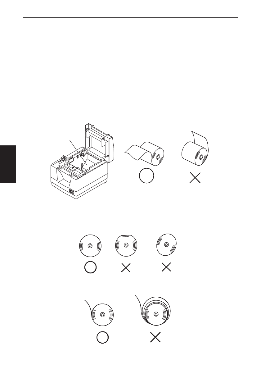
5. Caricamento della carta
5-1. Caricamento di un nuovo rotolo di carta
(1)Tirare la leva verso di sè per aprire il coperchio stampante.
Nota: Assicurarsi di tirare la leva fino a che si arresta al fermo. Se la leva non
viene tirata fino al fermo, il coperchio stampante può non aprirsi.
(2)Togliere l’adesivo dall’estremità della carta.
Nota: Assicurarsi di rimuovere completamente la parte adesiva, perché la
stampa non può essere eseguita su quella parte.
(3)Orientare la carta come indicato sotto e inserirla delicatamente nel comparto
carta.
Comparto carta
ITALIANO
Nota 1: Assicurarsi che il rotolo non sia deformato. Se si usa un rotolo come
quelli mostrati sotto, ne possono risultare problemi di funziona-
mento.
Nota 2: Se la carta è allentata come mostrato sotto dopo che è stata inserita
nel comparto carta, tenderla bene.
– 76 –
Page 81

(4)Assicurarsi che la carta sia collocata ben diritta e quindi chiudere delicatamen-
te il coperchio stampante.
Nota 1: Assicurarsi che la carta sia ben diritta. Se si chiude il coperchio
stampante con la carta storta come mostrato sotto, si può verificare
un inceppamento della carta.
Carta
Nota 2: Bloccare il coperchio della stampante premendo sul centro del
coperchio (indicato dalla freccia nella figura sotto). Se si preme una
parte del coperchio diversa dal centro, il coperchio può non
bloccarsi correttamente. Questo a volte rende impossibile la stam-
pa.
ITALIANO
– 77 –
Page 82

(5) Se l’interruttore di alimentazione è regolato su OFF, regolarlo su ON per
accendere la stampante. Assicurarsi che la spia ERROR non sia illuminata.
Nota: Mentre la spia ERROR è illuminata, la stampante non accetta alcun
comando come il comando di stampa, per cui assicurarsi che il
coperchio della stampante sia bloccato correttamente.
(6)Una volta che il coperchio stampante è stato bloccato, l’estremità della carta
fuoriesce e viene tagliata automaticamente.
5-2. Rimozione della carta rimanente
(1)Tirare la leva verso di sè per aprire il coperchio della stampante.
Nota: Assicurarsi di tirare la leva fino a che si arresta al fermo. Se la leva non
viene tirata fino al fermo, il coperchio stampante può non aprirsi.
(2)Estrarre la carta rimanente.
ITALIANO
– 78 –
Page 83
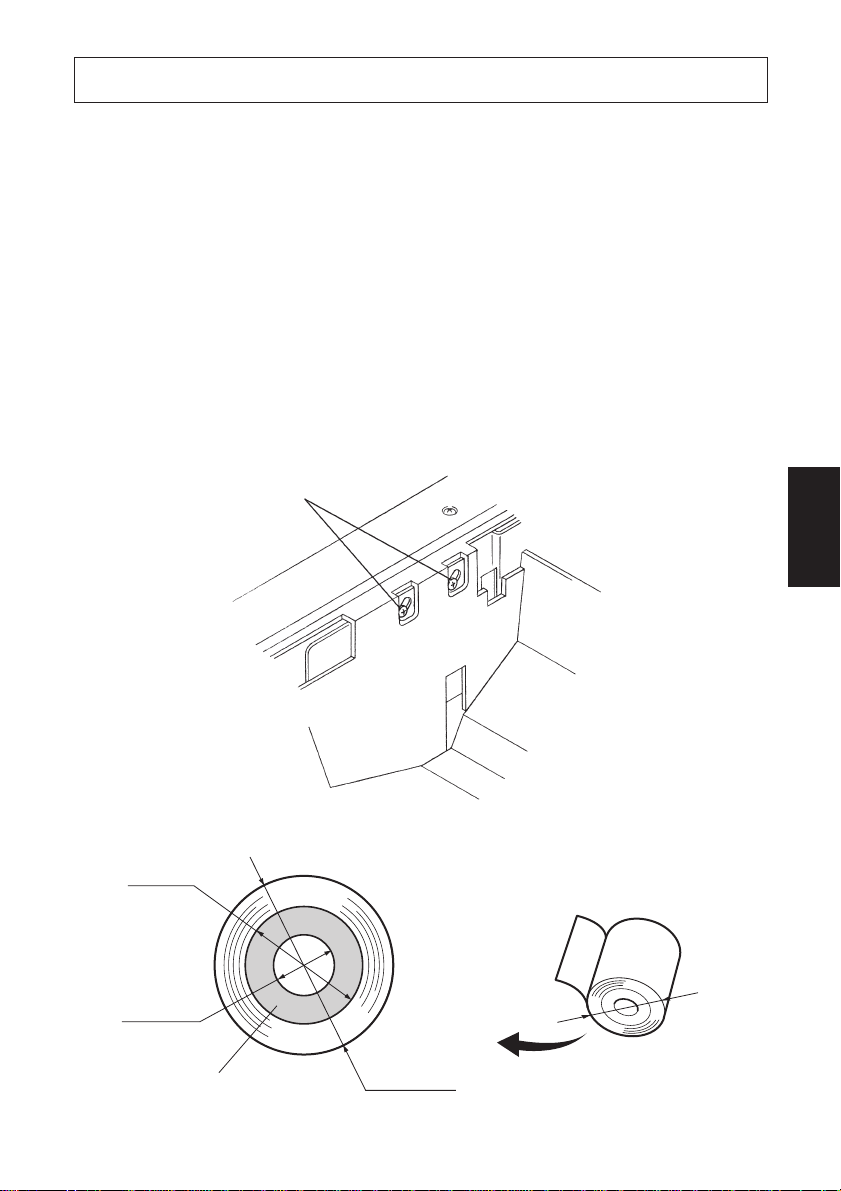
6. Sensore di rilevamento fine carta
Questa stampante è dotata di un sensore in grado di rilevare quando un rotolo di
carta sta per terminare. Leggere le seguenti istruzioni se si intende utilizzare
questa funzione.
(1)Tirare la leva nella direzione indicata su di essa e quindi aprire il coperchio
della stampante.
(2)Allentare le due viti di fissaggio del sensore.
(3)Spostare l’unità sensore in alto o in basso e quindi serrare bene le sue viti.
La seguente tabella mostra il diametro della carta che deve rimanere sul rullo
perché il sensore, installato alla specifica posizione di vite di fissaggio
sensore, possa individuarne la presenza.
Viti di fissaggio sensore
(Posizione 1)
ITALIANO
ø18 mm
ø12 mm
Centro del
rotolo di carta
A
A
– 79 –
Page 84

(4) Inserire il rotolo di carta e controllare che il sensore rilevi correttamente che
il rotolo sta per finire.
LED di errore Il LED non sia illuminata quando c’è carta.
Il LED lampeggia quando la carta è quasi esaurita.
Diametro della carta rimanente A Posizione vite
Circa ø22 mm Posizione 1 (fondo)
Circa ø26 mm Posizione 2 (cima)
Attenzione
1) L’impostazione di fabbrica è la posizione 1.
2) Per garantire un corretto rilevamento della quantità di carta rimanente,
utilizzare sempre rotoli di carta con una bobina avente un diametro interno di
12 mm ed un diametro esterno di 18 mm.
ITALIANO
– 80 –
Page 85
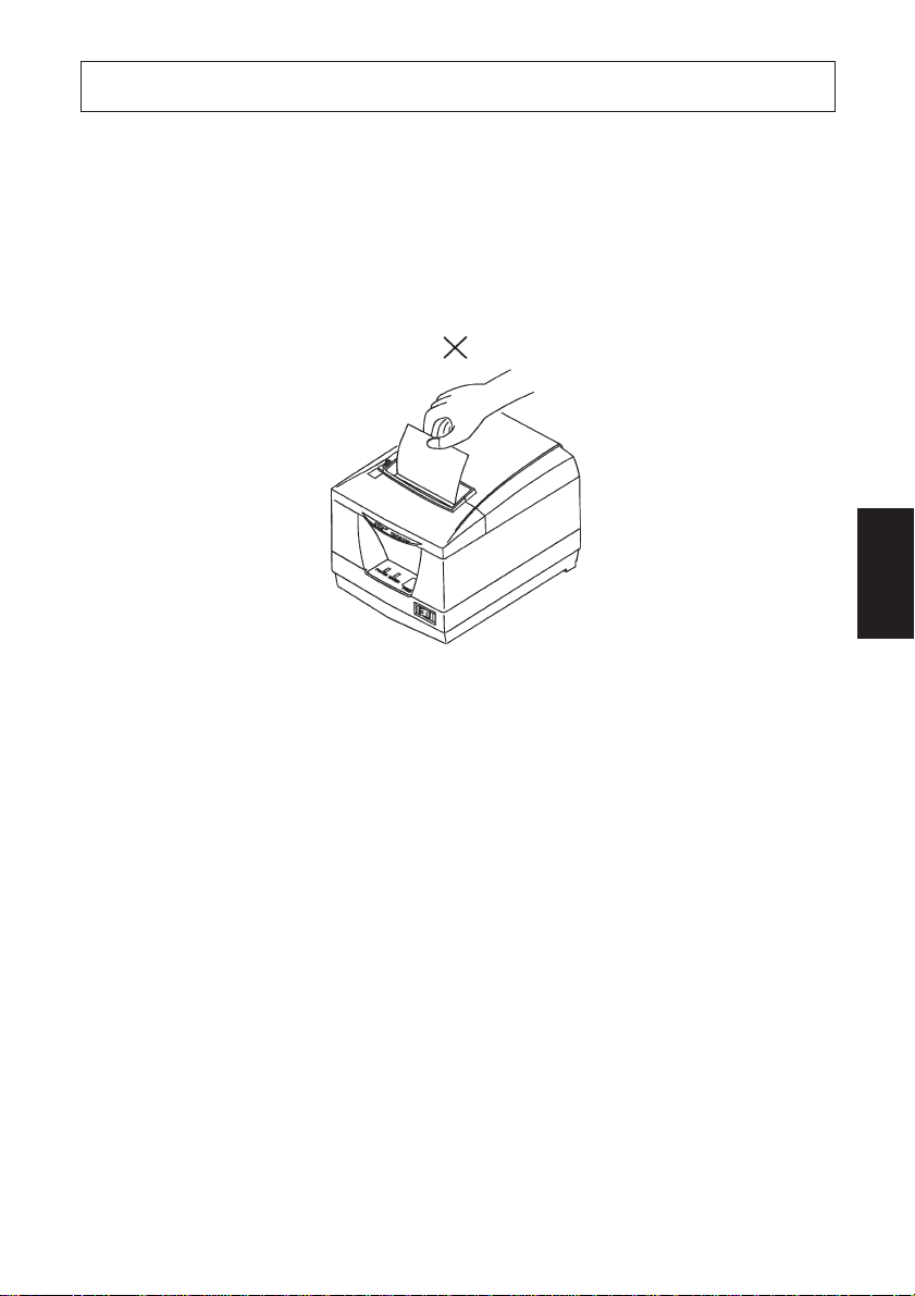
7. Prevenzione e soluzione degli inceppamenti della carta
7-1. Prevenzione degli inceppamenti della carta
La carta non deve essere toccata durante l’espulsione e prima che sia tagliata.
Se si preme o si tira la carta durante l’espulsione si può verificare un inceppamento
della carta, un mancato taglio della carta o un avanzamento di riga mancato. Non
aprire il coperchio stampante durante il taglio.
ITALIANO
7-2. Eliminazione degli inceppamenti della carta
Se si verifica un inceppamento della carta, eliminarlo come descritto di seguito.
(1)Regolare l’interruttore di alimentazione su OFF per spegnere la stampante.
(2)Tirare la leva verso di sè per aprire il coperchio stampante.
Nota: Assicurarsi di tirare la leva fino a che si arresta al fermo. Se la leva non
viene tirata fino al fermo, il coperchio stampante può non aprirsi.
(3)Rimuovere la carta inceppata.
Nota: Fare attenzione a non danneggiare la stampante quando si rimuove la
carta inceppata. Poiché la testina di stampa in particolare viene
danneggiata facilmente, fare attenzione a non toccarla.
– 81 –
Page 86

(4) Collocare diritto il rotolo di carta e chiudere delicatamente il coperchio
stampante.
Nota 1: Assicurarsi che la carta sia ben diritta. Se si chiude il coperchio
stampante con la carta storta, si può verificare un inceppamento
della carta.
Nota 2: Bloccare il coperchio della stampante premendo sul centro del
coperchio. Se si preme una parte del coperchio diversa dal centro,
il coperchio può non bloccarsi correttamente. Questo a volte rende
impossibile la stampa.
(5)Regolare su ON l’interruttore di alimentazione per accendere la stampante.
Assicurarsi che la spia ERROR non sia illuminata.
Nota: Mentre la spia ERROR è illuminata, la stampante non accetta alcun
comando come il comando di stampa, per cui assicurarsi che il
coperchio della stampante sia bloccato correttamente.
ITALIANO
7-3. Rilascio della taglierina bloccata
Se la taglierina automatica si blocca o non taglia la carta, procedere come segue.
Cautela:
Poiché lavorare con la taglierina può essere pericoloso, non dimenticare di
spegnere prima la stampante.
(1)Regolare l’interruttore di alimentazione su OFF per spegnere la stampante.
(2)Spostare il coperchio anteriore per scoprire la taglierina automatica.
(3)Rimuovere eventuale carta inceppata.
Nota: Fare attenzione a non danneggiare la stampante durante la rimozione
della carta inceppata.
Poiché la testina di stampa termica è particolarmente sensibile, fare
attenzione a non toccarla.
– 82 –
Page 87
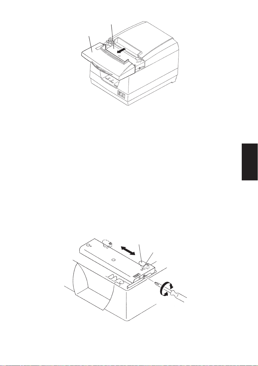
Taglierina automatica
Coperchio anteriore
(4)Se la lama mobile della taglierina sporge, usare un cacciavite Philips per girare
la vite a testa Philips e riportare la lama mobile alla sua posizione di partenza.
Quando la finestrella di controllo appare completamente bianca, la lama
mobile è nella sua posizione di partenza.
Nota 1: Non applicare estrema pressione alla lama mobile.
Nota 2: Se la lama mobile sporge eccessivamente, non è possibile aprire il
coperchio stampante. Se si tenta di aprire il coperchio stampante si
può danneggiare la taglierina.
(5)Aprire il coperchio stampante, rimuovere eventuale carta inceppata e quindi
reinstallare il rotolo di carta.
ITALIANO
(6)Installare il coperchio anteriore e quindi regolare l’interruttore di alimentazio-
ne su ON.
Lama mobile
Finestrella di controllo
– 83 –
Page 88

8. Metodo per la stampa di prova
8-1. Produzione di uno stampato di prova
Per avviare la stampa di prova, regolare su OFF l’interruttore di alimentazione,
inserire la carta e quindi regolare l’interruttore di alimentazione su ON tenendo
premuto il interruttore FEED. Rilasciare l’interruttore entro tre secondi.
Quando è stato eseguita una certa quantità di stampa, la stampante taglia la carta
e si ferma automaticamente.
8-2. Scaricamento esadecimali
Questo stampa i dati inviati dall’ospite in formato esadecimale e nei caratteri
ASCII corrispondenti. Questo è comodo per eliminare errori dalle applicazioni
e per analizzare caratteri confusi.
ITALIANO
Avvio ed arresto della stampa a scaricamento esadecimale
Tenendo premuto l’interruttore Feed, accendere l’unità. Tenere premuto
l’interruttore per cinque secondi; l’operazione di scaricamento esadecimale
inizia quando si rilascia l’interruttore. Se si rilascia l’interruttore entro tre
secondi, viene eseguito l’autocollaudo.
Spegnere l’unità per interrompere lo scaricamento esadecimale.
I dati ricevuti sono stampati come segue.
Indirizzo Dati esadecimali Dati ASCII
– 84 –
Page 89

9. Pulizia periodica
I caratteri stampati possono diventare parzialmente poco chiari a causa dell’accumulo di polvere di carta e sporcizia. Per evitare tale problema, è necessario
rimuovere periodicamente la polvere di carta accumulata nel comparto carta,
nella sezione di trasporto carta e sulla superficie della testina termica. Si consiglia
di eseguire questa pulizia una volta al mese.
9-1. Pulizia della testina termica
Per rimuovere la polvere nerastra accumulata sulla superficie della testina di
stampa, passarla con alcool (IPA)
Nota: La testina termica si danneggia facilmente, per cui pulirla delicatamen-
te con un panno morbido. Fare attenzione a non graffiarla durante la
pulizia.
9-2. Pulizia del comparto carta
Usare un panno morbido per eliminare la polvere di carta dal comparto carta e
dalla sezione di trasporto della carta.
ITALIANO
– 85 –
Page 90

ITALIANO
– 86 –
Page 91

Appendix A: Specifications
A-1. General Specifications
(1)Printing method Direct line thermal printing
(2)Print speed Max. 75 mm/s
(3)Dot density 203 dpi: 8 dots/mm (0.125 mm/dot)
(4)Number of print columns
48 (12 × 24 dots)
64 (9 × 24 dots): ESC/POS mode only
(5)Roll paper Refer to chapter 3 for details on the recommended
paper.
Paper width: 80 mm
Roll diameter: ø90 mm or less
External diameter of core: ø18 mm
Internal diameter of core: ø12 ± 0.5 mm
(6)Bar codes UPC-A, UPC-E, JAN 13 (EAN), JAN 8 (EAN),
CODE 39, CODE 93, CODE 128, ITF, CODA BAR
(7) Sensor Paper end, cover open, paper near end, abnormal
print head temperature
(8)Overall dimension 144 (W) × 195 (D) × 138 (W) (mm)
(9)Weight Approx. 1.48 kg
0
- 1.0
+0.5
0
Print Area
1 to 2
Paper feed direction
1 576
72±0.2
Print area
80
Paper width
0.125
0.125
576 dots
Print area 72±0.2
0
-1
Cutter position
*
1
Print head
4±14±1
printing position
Unit : mm
19.6±1
Note *1Since the firmware automatically feeds the paper 5 mm after it is cut,
the top cutter margin becomes 24.6±1.
– 87 –
APPENDIX
Page 92

A-2. Print Specifications
(1)Print width 72 mm (576 dots)
(2)Character size Front A: 1.50 × 3.00 mm
Front B (ESC/POS mode only): 1.13 × 3.00 mm
(3)Character structure Front A: 12 × 24 dots
Front B (ESC/POS mode only): 9 × 24 dots
(4)Character set ASCII: 96
Extended graphics: 128 × 8
International: 32
A-3. Auto Cutter Specifications
(1)Partial cut Cutting with one point left uncut
(2)Cutting frequency Max. 30 cuts per minute
(3)Thickness of paper Max. 0.08 mm
A-4. Interface
(1)Interface RS232C serial interface or Two-way parallel inter-
face (IEEE1284)
TM
(2)Command ESC/POS
APPENDIX
commands or Star commands
A-5. Power Supply
(1)AC Adaptor UP06021240, switching type
(2)Input 100 to 240V AC, 50/60 Hz
(3)Output DC 24V±5%, 2.5A MAX
(4)Power Consumption Operating: Approx. 65 VA (at print duty 14%)
Stand-by: Approx. 5 VA
(5)Power Connector
Signal
Pin No.
name direction
1 +24V Drive power IN
2 SG Signal GND
3 N.C.
Function
I/O
3
1
2
<Viewed from Connector Surface>
Note 1: This power connector is used to supply the control and mechanical
sections of the printer.
– 88 –
Page 93

Important!
• When using a printer power supply other than the optional AC adaptor
(UP06021240), be sure that the following cautions are observed.
• Use a power supply of DC 24 V ±5% and more than 2.5 A.
• Be careful about installing the printer in an area where there is noise.
Take the appropriate measures to protect against electrostatic AC line
noise, etc.
A-6. Environmental Requirements
(1)Operating
Temperature 5°C to 45°C
Humidity 10% to 90%
(%RH)
90
80
34°C 90%
60
40
Relative humidity
20
10
01020
Operating environment
range
30 40 50
Temperature (°C)
Operating temperature and humidity range
40°C 65%
45°C 50%
(2)Transport/storage (when packed)
Temperature -10°C to 50°C
Humidity 10% to 90%
A-7. Reliability
(1)MCBF 12.5 million lines
(2)Print head life Pulse durability: 100,000,000 pulses or more
Wear resistance: 50 km or more
(3)Cutter life 0.5 million cuttings (with designated paper)
APPENDIX
– 89 –
Page 94

Appendix B: Dip Switch Setting
Two DIP switches are provided at the bottom of the printer, and can be set as given
in the table below. Be sure to set the power switch to off before changing the
settings. It is recommended to use a pointed item like a pen or flat-blade driver
screw to change the settings. The settings will become effective when the power
switch is set to on again.
The following is the procedure for changing the settings on DIP switches.
1. Make sure the printer is turned off.
2. Remove the screw from the DIP switch cover. Then take off the DIP switch
cover, as shown in the illustration below.
APPENDIX
3. Set the switches using a pointed tool, such as a pen or flat-blade screwdriver.
– 90 –
Page 95

B-1. Serial Interface Type
ON ON
OFF OFF
No. 1
2 3 4 5 6 7 8
DIP-SW1
DIP-SW 1
Switch
1 Data receive error Error is ignored. “?” is printed.
2 Receive buffer size 68 bytes 4 k bytes
3 Handshaking XON/XOFF DTR/DSR
4 Data bit 7 bits 8 bits
5 Parity check Yes No
6 Parity Even Odd
7 Baud rate 19200 bps 9600 bps
8 Automatic status back function Valid Invalid
Function ON OFF
DIP-SW 2
Switch
1 Handshaking conditions Receive buffer full Offline or
(conditions for BUSY) receive buffer full
2 <FF> Code (Star mode) Cut Command Form Feed
Graphic Adjustment (ESC/POS mode) 180 DPI 203 DPI
3
Print density See Table 1.
4
5
Should not be changed (Should be set to off)
6 Command emulation ESC/POS mode Star mode
7 Pin #25 (INIT) reset signal Valid Invalid
8 Pin #6 (DSR) reset signal INIT DSR
Function ON OFF
No. 1
2 3 4 5 6 7 8
DIP-SW2
——
APPENDIX
Table 1 Print Density
Print Density SW2-3 SW2-4
Power economy mode ON ON
Standard OFF OFF
▼
▼
Dark OFF ON
ON OFF
– 91 –
Page 96
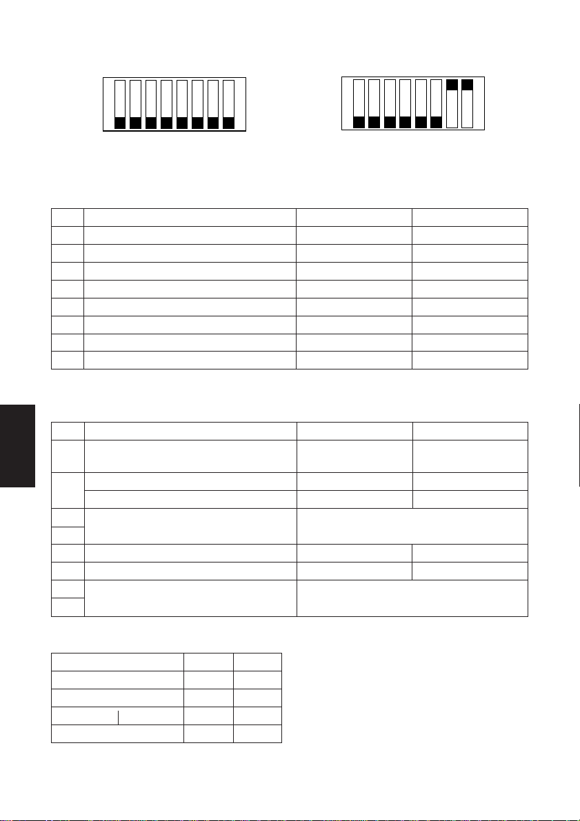
B-2. Parallel Interface Type
No. 1
DIP-SW2
2 3 4 5 6 7 8
ON ON
OFF OFF
No. 1
2 3 4 5 6 7 8
DIP-SW1
Switch
1 Auto CR Valid Invalid
2 Receive buffer size 68 bytes 4 k bytes
3
4 Device ID reply Valid Invalid
5 Automatic status back function Valid Invalid
6 Negotiation status back function Valid Invalid
7
8 Cut position adjust *
APPENDIX
Switch
1 Handshaking conditions Receive buffer full Offline or
2 <FF> Code (Star mode) Cut Command Form Feed
3
4
5
6 Command emulation ESC/POS mode Star mode
7
8
Should not be changed (Should be set to off)
Treatment of missing data during reverse mode
(conditions for BUSY) receive buffer full
Graphic Adjustment (ESC/POS mode) 180 DPI 203 DPI
Print density See Table 2.
Should not be changed (Should be set to off)
Always ON Should be set on
Function ON OFF
Function ON OFF
DIP-SW 1
——
Store Delete
1
Valid Invalid
*1 ESC/POS mode only
DIP-SW 2
——
Table 2 Print Density
Print Density SW2-3 SW2-4
Power economy mode ON ON
Standard OFF OFF
▼
▼
Dark OFF ON
ON OFF
– 92 –
Page 97
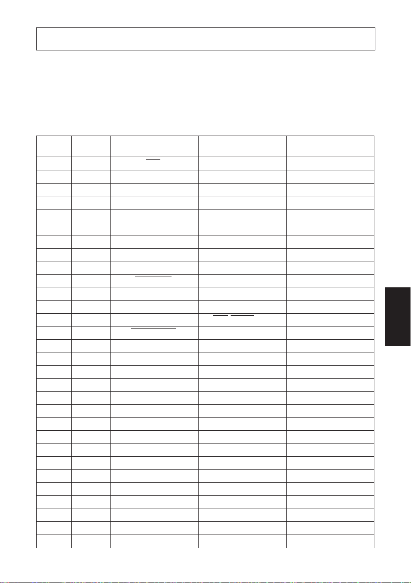
Appendix C: Parallel Interface
The two-way parallel interface is compatible with the IEEE1284 compatibility
mode, nibble mode and byte mode. Refer to the separate programmer’s manual
for details.
C-1. Table of Connection Signals for Each Mode
Pin No. Direction
Compatibility Mode Nibble Mode Byte Mode
Signal Name Signal Name Sginal Name
1 In STB Host Clock Host Clock
2 In/Out DATA0 DATA0 DATA0 *
3 In/Out DATA1 DATA1 DATA1 *
4 In/Out DATA2 DATA2 DATA2 *
5 In/Out DATA3 DATA3 DATA3 *
6 In/Out DATA4 DATA4 DATA4 *
7 In/Out DATA5 DATA5 DATA5 *
8 In/Out DATA6 DATA6 DATA6 *
9 In/Out DATA7 DATA7 DATA7 *
10 Out ACK OUT Ptr Clock *
11 Out BUSY OUT Busy/DATA3,7 *
12 Out PE OUT AkDR/DATA2,6 *
13 Out SELECT OUT Xflg/DATA1,5 *
14 In AUTOFD IN HOSTBUSY *
1
1
1
1
1
Ptr Clock *
HOSTBUSY *
15 NC NC NC
16 GND GND GND
17 FG FG FG
18 OUT Logic H Logic H Logic H
19 GND GND GND
20 GND GND GND
21 GND GND GND
22 GND GND GND
23 GND GND GND
24 GND GND GND
25 GND GND GND
26 GND GND GND
27 GND GND GND
28 GND GND GND
29 GND GND GND
30 GND GND GND
1
1
1
1
1
1
1
1
1
Busy
AkDR
Xflg
1
APPENDIX
– 93 –
Page 98

Pin No. Direction
31 In INT IN INT IN INT IN
32 Out ERROR OUT DATAAV/DATA0.4 *
33 GND GND GND
34 Out DKSTS — —
35 Out Logic H Logic H Logic H
36 In SELECT IN 1284 Active *
APPENDIX
Compatibility Mode Nibble Mode Byte Mode
Signal Name Signal Name Sginal Name
1
1
DATAAV
1284 Active *
*1 During Reverse mode
1
– 94 –
Page 99
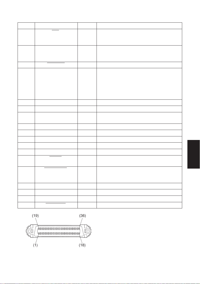
C-2. Function for Compatibility Mode
Pin No. Signal Name IN/OUT Function
1 STB IN Signals when data is ready to be read. Signal goes
from HIGH to LOW (for at least 0.5 microsec.) when
the data is available.
2-9 DATA0-7 IN These signals provide the information of the first to
eighth bits of parallel data. Each signal is at HIGH level
for a logical 1 and at a LOW level for a logical 0.
10 ACK OUT OUT LOW pulse acknowledges receipt of the data.
11 BUSY OUT OUT When this signal goes to LOW, the printer is ready
to accept data. When the printer is in one of the
conditions below, “HIGH” is set.
1. Data is being entered
2. Off line
3. Error condition
12 PE OUT OUT This signal indicates the status of the paper sensor.
13 SELECT OUT OUT This signal is HIGH when the printer is online.
14 AUTO IN IN This signals that the printer is processing a paper
feed command from a host computer.
15 NC Unused
16 GND Signal ground
17 FG Chassis ground, isolated from logic ground
18 Logic High
19-30 GND Twisted pair return the signal to ground level.
31 INT IN IN When this signal goes to LOW, the printer is reset to
its power-on condition.
32 ERROR OUT OUT This signal is normally HIGH. This signal goes to
LOW to signal that the printer cannot print due to an
error condition.
33 GND External ground
34 DKSTS OUT
35 Logic High
36 SELECT IN IN Puts printer in Select mode
APPENDIX
This connector mates with an
Amphenol 57-30360 connector
Parallel interface connector (printer side)
– 95 –
Page 100

Appendix D: Serial Interface
D-1. RS-232C Connector
Pin No.
1 FG Frame ground
2 TXD Send data OUT
3 RXD Receive data IN
4 RTS Request to send OUT
5–
6 DSR Data set ready IN
7 SG Signal GND
8–
9–
10 –
11 –
12 –
13 –
APPENDIX
Signal
name direction
Function
13 12 11 10 9 8 7 6 5 4 3 21
25 24 23 22 21 20 19 18 17 16 15 14
I/O
<Viewed from Connector Surface>
Signal
Pin No.
name direction
14 –
15 –
16 –
17 –
18 –
19 –
20 DTR Data terminal ready OUT
21 –
22 –
23 –
24 –
25 INIT Reset IN
Function
I/O
– 96 –
 Loading...