

Page 1

High-Precision Advanced
Tuning Fork Balance
MG-S
Operation
•
To ensure safe and proper use of the balance, please read this
manual carefully.
•
After reading this manual, store it in a safe place near the balance, so
you can review it as needed.
IMPORTANT
Series
Manual
S t a r M i c r o n i c s
450017M21
Page 2

Page 3

-i-
Preface
Thank you very much for having purchased our Tuning-Fork high precision electronic balance MG-S
series.
This document describes how to operate the product.
Instructions
●
The copyright of this document belongs to Star Micronics. Reprinting or duplicating of all or part
of this document without notice shall not be allowed.
●
Please note that product improvement or modification may cause partial discrepancy between
the product and the description of this document.
●
The description of this document is subject to change without notice.
●
This document has been created carefully. In case that, however, any error or imperfection is
found by any chance, please let us know.
●
Documents of which pages are missing or irregularly bound will be exchanged. Please inform
the store where you purchased the product.
●
Trouble related to the product or system will be dealt with in accordance with the individual
maintenance contract. Please note, however, that we will not take responsibility for
consequential trouble such as discontinuation of operation caused by the product trouble.
●
is the registered trademark of Star Micronics. Company names and product
names appearing in this document are the trademarks or registered trademarks of the
respective company concerned.
●
The Bluetooth® word mark and logos are registered trademarks owned by the
Bluetooth SIG, Inc. and any use of such marks by Star Micronics is under license. Other
trademarks and trade names are those of their respective owners.
●
Microsoft, Windows are either trademarks or registered trademarks of Microsoft Corporation in
the Unites States and/or other countries.
Page 4

-ii-
Important Notice
・It should be known that this product contains potential danger. And so
please be sure to observe this document when installing, operating or
servicing this product.
・Star Micronics will not take any responsibility for any injury or damage
caused by the non-observance of this document or misuse or unauthorized
modification of this product.
●
Potential dangers are increasing in the industrial equipment industries due to the advent
of new materials and processing methods, and speeding up of machines. It is
impossible to foresee all situations related to these dangers. In addition, there are so
many “impossible” and “don’ts” and so writing all of them in the operation manual is
impossible. Therefore, it is safe to think that what is not written in the operation manual
“cannot be performed” unless the operation manual positively writes “it is possible.”
When performing installation, operation, maintenance or inspection of this product, not
only observe what is written or indicated in this document or on the product surface but
also pay adequate consideration to safety measures.
●
The copyright of this document is held and reserved by Star Micronics. Duplicating or
disclosing its drawings and engineering materials without prior approval of Star
Micronics in writing is not permitted.
●
For any question or further information concerning this document, please contact the
store where you purchased the product or with its model (type) name and serial number
informed.
●
Manufacturer: Star Micronics America, Inc.
Address: 65 Clyde Road Suite G, Somerset, NJ 08873 U.S.A.
Tel: (800) 782-7636 / (848) 216-3300
Email: support@starmicronics.com
Page 5
-iii-
How to use this document
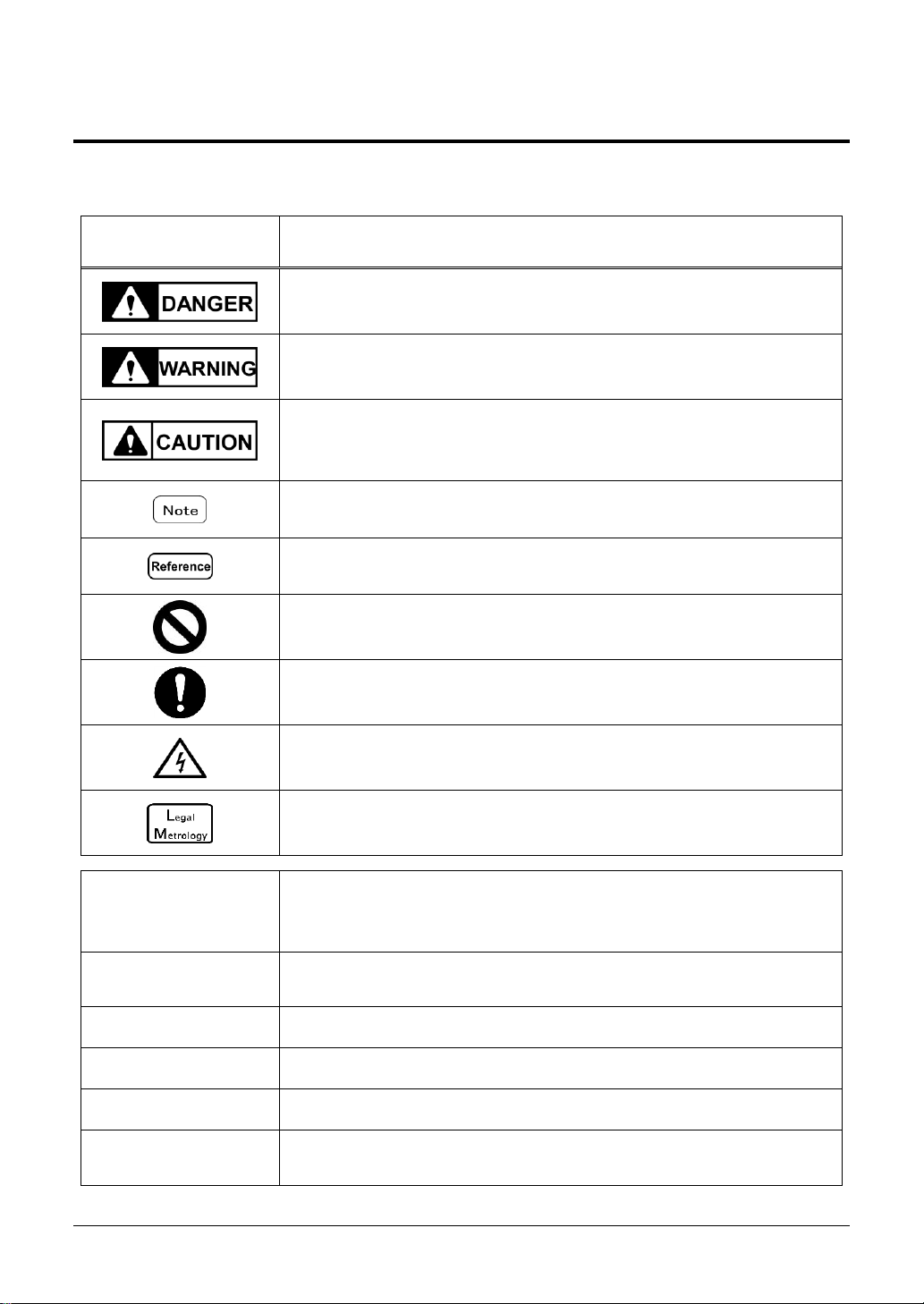
■Symbols used in this document
Understand the meaning of the following symbols and observe the instructions of this document.
Symbols
Meaning
Used for the situation that invites an imminent risk of death or severe injury if
proper precautions are not taken.
Used for the situation that invites a risk of death or serious injury if proper
precautions are not taken.
Used for caution concerning operations that may lead to a light physical
injury to persons or damage of the products/facilities if proper precautions
are not taken.
Used for notation for avoiding from delection, overwrite the weighing data or
for accurate weighing and appropriate usage of the equipment.
Used for reference information on operation
Used for “Prohibition” items
Used for “Mandatory” items requiring positive action
Used for prohibition items to avoid “Electrical shock”.
This symbol indicates the operation/specification related to NTEP approval
and verification.
This product/
The product/
The balance
Refers to the product.
[On/Off] key
The name of an operation key located in front of the main unit is
represented in square brackets “[ ]”.
<message>
A message on the display is represented in angle brackets “< >”.
<<F1>>
“Free key” or “Shortcut” is represented in double angle brackets “<< >>”.
Push the key
Signifies pushing lightly an operation key once.
Push the key long
Signifies keeping pushing an operation key until the designated indication
appears.
Page 6

-iv-
■About how to read this document
This document consists of the following contents:
1
Prior to use
Describes about operating precautions, names and functions of each
section, etc. Please be sure to read this section when using this product
for the first time.
2
Basic usage
Describes about basic usage related to weighing such as how to turn on
and off the power in addition to the setting procedures to set various
functions.
3
Functions related to the
operation
Describes about setting items to change the operation of the balance.
4
Function related to the
performance
Describes about setting items related to the indication stability and the
response speed of the balance.
5
User information
setting
Describes about setting items related to the upper and lower limits and
preset tare weight.
6
External input/output
functions
Describes about setting items related to the specifications and conditions
in regard to the external communication.
7
Functions related to the
lock
Describes about setting items related to change prohibitions and invalid
keystrokes on each menu item.
8
Controlling and
adjustment functions
Describes about setting items related to the product administrator.
9
Troubleshooting
Describes about methods of troubleshooting this product such as how to
respond to errors and when you are in need of help.
10
How to maintain
Describes how to maintain this product.
Appendix
Provides necessary data such as the specifications of this product.
Page 7

-v-
Contents
Preface ........................................................................................................................................ i
Important Notice ....................................................................................................................... ii
How to use this document ...................................................................................................... iii
Contents .................................................................................................................................... v
1 Prior to use .......................................................................................................................... 1
1-1 Operating precautions .................................................................................................... 1
1-2 For more accurate measurement ................................................................................... 3
1-2-1 Precautions related to measuring environment ........................................................... 3
1-2-2 Precautions related to measuring table ....................................................................... 3
1-2-3 Precautions related to a specimen .............................................................................. 4
1-2-4 Precautions related to the main unit of a balance ....................................................... 4
1-3 Check for the articles contained in the box..................................................................... 5
1-4 Name and function of each section ................................................................................ 6
1-5 Assembling and installation of the product ..................................................................... 7
1-5-1 Assembling the balance (Round pan type MG-S322) ................................................. 7
1-5-2 Assembling the balance (Square pan type MG-S1501, MG-S8200) ......................... 8
1-5-3 Level ........................................................................................................................... 9
1-6 Description of the operation keys ................................ ................................................. 10
1-6-1 Basic ......................................................................................................................... 10
1-6-2 Setting value and numeric value inputting................................................................. 11
1-7 How to interpret the display .......................................................................................... 12
1-7-1 Description of segment. ............................................................................................ 12
1-7-2 LCD character font .................................................................................................... 13
2 Basic usage ....................................................................................................................... 14
2-1 Turning on/off the power, and checking for the operation ............................................. 14
2-2 Zero-point adjustment .................................................................................................. 15
2-2-1 Zero-point adjustment range ..................................................................................... 15
2-3 Weighing a sample placed on a container (tare) .......................................................... 15
2-4 Weighing the additional sample ................................................................................... 17
2-5 Basic operation ............................................................................................................ 17
2-5-1 Hierarchy of a setting menu ...................................................................................... 17
2-5-2 Operation of the setting menu ................................................................................... 18
2-5-3 Numeric value input .................................................................................................. 19
2-5-4 [ F ] key switching at each measuring mode ............................................................. 20
3 Functions related to the operation .................................................................................. 21
3-1 Hierarchy of functions related to the operation ............................................................. 21
3-2 Various measuring modes of the balance .................................................................... 22
3-2-1 Weighing mode ......................................................................................................... 22
3-2-2 Counting mode .......................................................................................................... 23
3-2-2 (1) Actual value setting method ................................................................................. 23
3-2-2 (2) Numeric value setting method ............................................................................. 25
3-2-2 (3) Switching the display at Counting mode .............................................................. 26
3-3 Percentage mode ......................................................................................................... 27
3-3-1 Switching the display at percentage mode ................................................................ 29
3-4 Multiplied by Coefficient mode ..................................................................................... 30
3-4-1 Switching the display at Multiplied by Coefficient ...................................................... 31
3-5 Specific gravity mode ................................................................................................... 32
3-5-1 Switching the display at “Specific gravity mode” ....................................................... 33
3-6 Statistics mode ............................................................................................................. 34
Page 8

-vi-
3-6-1 Switching the display at “Statistics mode” ................................................................. 35
3-7 Animal mode ................................................................................................................ 36
3-8 Formulation mode ........................................................................................................ 38
3-8-1 Check the stored data of each component................................................................ 39
3-9 Unit setting ................................................................................................................... 40
3-10 Comparator function ................................................................................................... 40
3-10-1 How to perform discrimination ................................................................................. 40
3-10-2 Comparator function setting .................................................................................... 41
3-11 Adding function ........................................................................................................... 42
3-11-1 Weighing by means of the plus side addition .......................................................... 43
3-11-2 Weighing by means of the minus side addition ....................................................... 44
3-12 Tare-subtraction reminder function ............................................................................. 45
3-13 Zero-point-adjustment reminder function ................................................................... 46
3-14 Bar graph indication ................................................................................................... 46
3-15 Stabilization wait setting ............................................................................................. 47
3-16 Backlight setting ................................................................................................ ......... 47
3-17 Auto power-off ............................................................................................................ 48
3-18 “Simple SCS(Self Counting System) method” setting ................................................ 48
4 Functions related to the performance ............................................................................. 49
4-1 Hierarchy of functions related to the performance ........................................................ 49
4-2 Stability discrimination width ........................................................................................ 49
4-3 Response speed .......................................................................................................... 50
4-4 Zero tracking ................................................................................................................ 50
5 User information setting ................................................................................................... 51
5-1 Hierarchy of user information setting ............................................................................ 51
5-2 Preset tare .................................................................................................................... 52
5-2-1 Preset tare setting ..................................................................................................... 52
5-2-2 Inputting of a preset tare weight value ...................................................................... 52
5-2-2 (1) Actual value setting method ................................................................................. 53
5-2-2 (2) Numeric value setting method ............................................................................. 53
5-2-2 (3) Exiting the preset tare mode ................................................................................ 53
5-3 Setting of the discrimination value of the comparator function ..................................... 54
5-3-1 Actual value setting method ...................................................................................... 55
5-3-2 Numeric value setting method ................................................................................... 55
6 External input/output functions ....................................................................................... 56
6-1 Hierarchy of the external input / output functions ......................................................... 56
6-2 Standard RS-232C Connecter terminal numbers and their functions ........................... 59
6-3 Standard USB Connecter terminal numbers and their functions .................................. 59
6-4 Communication format ................................................................................................. 60
6-4-1 Basic communication specification ........................................................................... 60
6-4-2 Basic data output format / CSP format ...................................................................... 60
6-4-3 Generic format .......................................................................................................... 62
6-5 Input command ............................................................................................................ 64
6-5-1 Transmission procedure ............................................................................................ 64
6-5-2 Input command composition 1 .................................................................................. 65
6-5-2 (1) Zero-point adjustment/Tare/Output control setting command .............................. 65
6-5-2 (2) Date output request and time output request ....................................................... 65
6-5-3 Input command composition 2 .................................................................................. 66
6-5-3 (1) Comparator setting command ............................................................................. 66
6-5-3 (2) Preset tare value setting command ..................................................................... 66
6-5-3 (3) Interval (output) time setting command................................................................ 66
6-6 Response ..................................................................................................................... 67
Page 9

-vii-
6-6-1 Response command format (“A00”/“Exx” format) ..................................................... 67
6-6-1(1) Response command ............................................................................................. 67
6-6-2 Response command format (“ACK”/“NAK” format) ................................................... 67
6-6-2(1) Response command ............................................................................................. 67
6-7 External contact input ................................................................................................... 67
6-8 Communication setting ................................................................................................. 68
6-8-1 RS232C/USB/Bluetooth ............................................................................................ 68
6-8-2 Bluetooth initialization .................................................................................................. 70
7 Functions related to the lock............................................................................................ 71
7-1 Hierarchy of functions related to the lock ..................................................................... 71
7-2 Total lock release ......................................................................................................... 71
7-3 Key lock function ................................ ................................ .......................................... 72
7-4 Menu lock function ....................................................................................................... 72
8 Controlling and adjustment functions ............................................................................. 73
8-1 Hierarchy of controlling and adjustment functions ........................................................ 73
8-2 Shortcut setting for accessing various measuring modes ............................................ 75
8-3 Free key setting ............................................................................................................ 76
8-4 Maintenance settings ................................................................................................... 77
8-4-1 Span calibration and span test .................................................................................. 77
8-4-1(1) Span calibration with external weight.................................................................... 77
8-4-1(2) Span test with external weight .............................................................................. 79
8-5 Balance control setting ................................................................................................. 80
8-5-1 Balance ID setting ..................................................................................................... 80
8-5-2 Password control ...................................................................................................... 80
8-5-2 (1) Administrator password registration..................................................................... 81
8-5-2 (2) User password registration ................................ .................................................. 81
8-5-3 Outputting of the span calibration/ test result ............................................................ 82
8-5-4 Date indication format ............................................................................................... 82
8-5-5 Date setting ............................................................................................................... 82
8-5-6 Time setting............................................................................................................... 83
8-5-7 Direct start setting ..................................................................................................... 84
8-5-8 Initialize ..................................................................................................................... 84
9 Troubleshooting ................................................................................................................ 85
9-1 Error message .............................................................................................................. 85
10 How to maintain ............................................................................................................... 88
10-1 Simple Method for Maintenance (Round pan type MG-S322) .................................... 88
10-2 Simple Method for Maintenance (Square pan type MG-S1501, MG-S8200).............. 89
Appendix ................................................................................................................................. 90
Appendix 1 Specification .................................................................................................... 90
Appendix 1-1 Basic Specification ....................................................................................... 90
Appendix 1-2 Functional specification ................................................................................ 91
Appendix 2 Dimensional outline drawing ............................................................................ 93
Appendix 3 Unit indication and conversion table ................................................................ 94
Appendix 4 Installation of batteries ..................................................................................... 95
Appendix 5 USB communication and bus power input ....................................................... 96
Appendix 6 Balance operation with password control function ........................................... 97
Appendix 6-1 User’s authority setting ................................................................................. 97
Appendix 6-2 User/guest login ........................................................................................... 98
Appendix 7 Windshield assembly instructions .................................................................... 99
Index of Terms ....................................................................................................................... 102
Page 10

Page 11
MG-S series operation manual 1 Prior to use
-1-
1 Prior to use
1-1 Operating precautions
■Do not wet the AC adapter.
That may cause an electric shock, short-circuiting or failure.
■Do not handle the balance with wet hands.
That may cause short-circuiting or failure.
■Do not use the balance in a wet location.
That may cause an electric shock, short-circuiting or failure.
■Do not connect to the AC adapter cord or communication cable with its connector
or jack being wet.
That may cause an electric shock, short-circuiting or failure.
■Do not use the balance in a dusty location.
That may cause dust explosion or fire.
That may cause short-circuit or malfunction of the balance.
■Do not use the balance in explosive atmosphere.
That may cause explosion or fire.
Please order our explosive-proof balances to weigh in such a hazardous area.
■Never disassemble or modify the batteries. Make sure you insert batteries with the
positive and negative poles correctly inserted, and be careful of short circuits.
Such mishandling could damage the batteries, or cause the balance to fail.
■Obey the MSDS.
Measuring dangerous materials such as flammable liquid could cause an explosion or fire.
■Do not disassemble or modify the product.
Doing so could result in injury, electric shock, fire and other accidents or failures. For inspection and
adjustment, contact the retailer from whom the product was purchased.
■Do not move the product with a sample to be weighed set on the balance.
That may cause the sample to fall from the weighing pan, leading to a bodily injury or destruction of the
sample.
■Do not route the AC cord across passages.
The cord could be tripped on by a passerby and the balance could fall down and break or injure
someone.
■Do not use the product on an unstable table or a place that is subject to vibration.
That may cause the sample to fall from the weighing pan, leading to a bodily injury or destruction of the
sample. Besides inaccurate weighing may result.
■Do not place an unstable sample on the weighing pan.
The sample may fall down, giving rise to a danger. Put an unstable sample in a container (tare) before
weighing it.
■Only use the specified power supply.
Using any power supply other than that specified could cause overheating, fire or failure.
■Do not bring the balance by holding the windshield.
The main body could drop and break down or injury someone. Make sure to hold the main body to bring
the balance.
■Do not use the product in an abnormal condition.
If it should happen that an abnormal event such as smoking or unusual odor occurs, ask the store
where you purchased the product or our sales department for repair. Keeping using the product may
result in an electric shock or fire. In addition, do not ever try to repair it for yourself, or very dangerous
situation is likely to occur.
■Only use the dedicated AC adapter.
Use of other types of power or adapters may result in heat generation or malfunction of the balance.
Page 12
1 Prior to use MG-S series operation manual
-2-
■Do not mix old and new batteries, or batteries of different types or manufacturers.
■Do not use the batteries that leak.
■Do not apply excessive force to or impact the balance.
Doing so could damage or result in failure of the balance. Carefully place samples on the balance.
■Do not use volatile solvents.
The main unit could deform. Wipe the main unit using dry cloth or a cloth moistened with a small
amount of neutral detergent.
■ Dispose of batteries in accordance with local regulations.
■ If the balance is not going to be used for a long time, store it with the batteries
removed.
■Observe the precautions printed on the batteries used.
FCC
caution
■Changes or modifications not expressly approved by the party responsible for
compliance could void the user's authority to operate the equipment.
■Do not install the balance in a place where it is directly exposed to airflow from air-
conditioning or heating equipment.
Due to changes in the ambient temperature, the balance could fail to accurately weigh samples.
■Do not install the balance in a place exposed to direct sunlight.
The internal temperature of the balance could rise and the balance could fail to accurately weigh
samples.
■Do not install the balance where the floor is soft.
When a sample is placed on the balance, the balance could slant and fail to accurately weigh samples.
■Do not install the balance in a place where the ambient temperature or humidity
change significantly.
The balance could fail to accurately weigh samples.
■Adjust (calibrate) the balance when it is installed or relocated.
Failure to do so might result in measurement errors. To ensure accurate measurements be sure to
adjust (calibrate) the balance.
■Check for an error periodically.
Use environment and chronological change cause an error in measured value, leading to an inaccurate
measurement.
■Unplug the AC adapter from the receptacle when the balance is not going to be
used for a long period of time.
Unplug the balance from the receptacle to save energy and prevent degradation.
■Always adjust the level of the balance before use.
A tilted balance generates errors which might cause inaccurate weighting.
■For proper disposal
This product including accessories may not be disposed of in domestic waste in conformance with
the specific requirements in your country or state.
When you dispose of this product, please contact your local authorities or dealer and ask for the correct
method of disposal.
FCC
Note
This device complies with part 15 of the FCC Rules. Operation is subject to the following
two conditions:
(1) This device may not cause harmful interference, and
(2) this device must accept any interference received, including interference that may cause undesired
operation.
This equipment has been tested and found to comply with the limits for a Class A digital device,
pursuant to part 15 of the FCC Rules. These limits are designed to provide reasonable protection
against harmful interference when the equipment is operated in a commercial environment. This
equipment generates, uses, and can radiate radio frequency energy and, if not installed and used in
accordance with the instruction manual, may cause harmful interference to radio communications.
Operation of this equipment in a residential area is likely to cause harmful interference in which case
the user will be required to correct the interference at his own expense.
This product contains unlicensed transmitting module:
- Name: Stand-alone dual-mode Bluetooth module OBS421 series
- Model number: CB-OBS421i-i4-01B
- FCC ID: PVH0946
Page 13
MG-S series operation manual 1 Prior to use
-3-
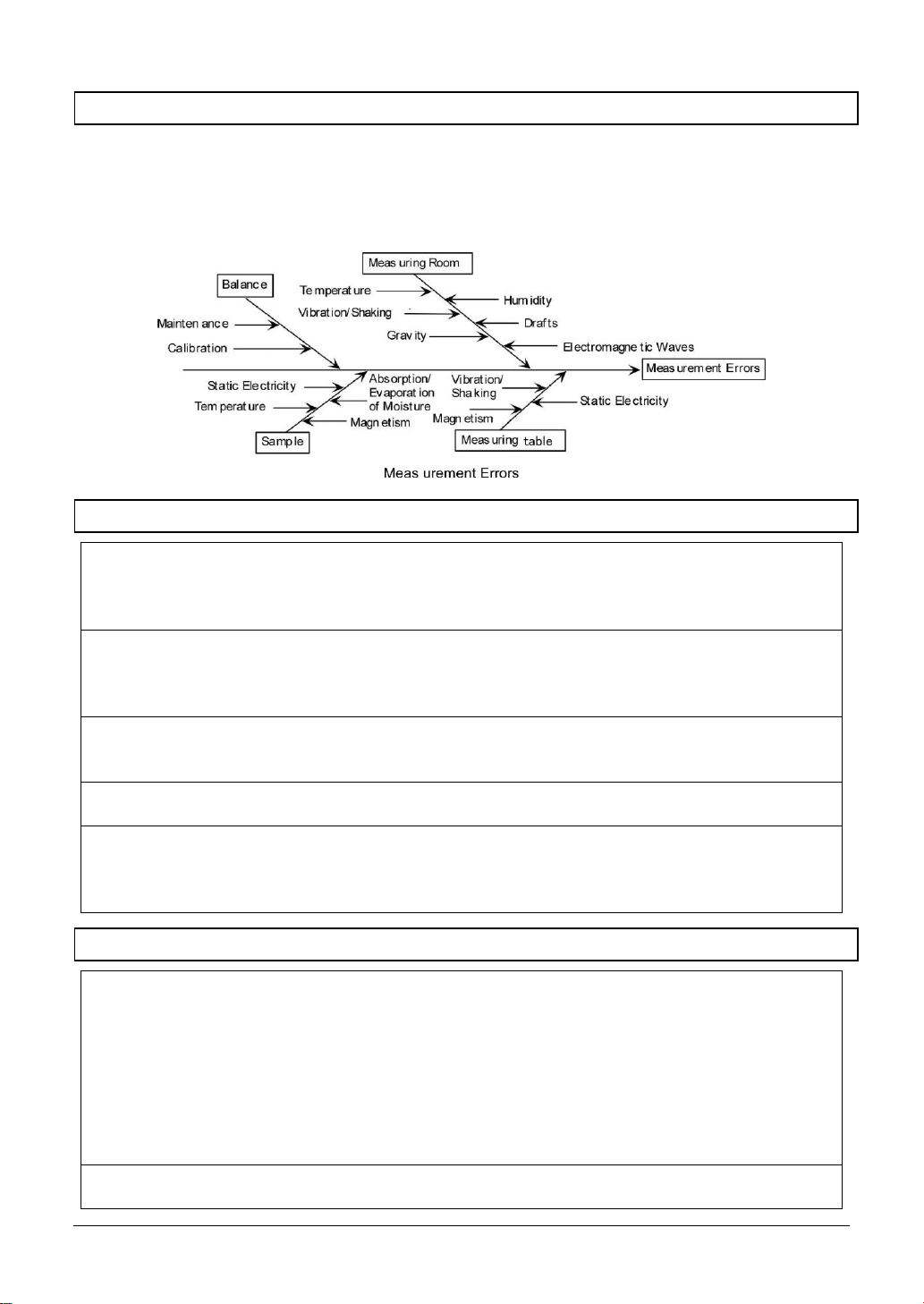
1-2 For more accurate measurement
To make more accurate measurement, it is necessary to lessen error-causing factors in measurement
to the extent possible. Error-causing factors include not only an instrument error and performance of
the balance itself but also the nature and condition of a specimen, measuring environment (vibration,
temperature, humidity, etc.) and the like. These factors will directly affect measurement result in the
case of a balance with high resolution capability.
1-2-1 Precautions related to measuring environment
Temperature/
humidity/
atmospheric
pressure
→
Try to keep the room temperature constant to the extent possible in order to
avoid condensation and indication drift due to change in temperature.
→
Low humidity is likely to cause generation of static electricity, resulting in
inaccurate measurement.
Vibration/shaking
→
It is preferable to locate a measuring room on the first floor or the basement. The
higher the room is, the larger the vibration and shaking become. Therefore, a
highly located room is not suitable for measurement. Rooms near the railway or
road side should also be avoided.
Air draft
→
Places directly exposed to air current from an air-conditioner or to direct sun
generate abrupt temperature change and resultantly cause unstable weight
indication, and therefore, should be avoided.
Gravity
→
The latitude and altitude of a measuring location differentiate the gravity that
affects a specimen, giving a different weight indication to the same specimen.
Electromagnetic
wave
→
At a location where a strong electromagnetic wave generating object is in the
proximity of a balance, the balance is affected by the electromagnetic wave,
making the balance unable to indicate accurate weight, and therefore, such a
location should be avoided.
1-2-2 Precautions related to measuring table
Vibration/shaking
→
Vibrations during measurement destabilizes the indication of measurement
value, leading to inability to make accurate measurement. And so use of a
measurement table that is robust and hardly affected by vibration is required (a
vibration-proof structured table or concrete or stone-made table is suitable). In
addition, placing a sheet of soft cloth or paper under the balance causes shaking
or makes keeping horizontal attitude difficult, and therefore should be avoided.
→
The measurement table should be installed in a position free from vibration to
the extent possible. A corner rather than the center of a room is less affected by
vibration and therefore more suitable for installation of the balance.
Magnetism/Static
electricity
→
Use of the balance on the table that is subject to magnetism or static electricity
should be avoided.
Page 14

1 Prior to use MG-S series operation manual
-4-
1-2-3 Precautions related to a specimen
Static electricity
→
In general, synthetic resin- and glass-made specimens are high in electric
insulation, and so easily charged electrically. Weighing an electrically charged
specimen makes the indication value unstable, reducing the reproducibility of
the test result. Therefore, neutralize an electrically charged specimen before
measurement.
Magnetism
→
Specimens affected by magnetism show different weight in a different position
of the weighing pan, reducing the reproducibility.
When weighing a magnetized specimen, either eliminate the magnetism from
the specimen or place a setting plate on the weighing pan to distance the
specimen from the weighing mechanism of the balance so that the mechanism
may not be affected by the magnetism.
Moisture
absorption/
Evaporation
→
Measuring a moist or evaporating (vaporizing) specimen increases or
decreases the indication value of the balance continuously. When this is the
case, put the specimen in a container equipped with a small mouth and closely
seal the mouth before measurement.
Specimen
temperature
→
Difference in temperature between the specimen and the windshield interior
generates convection flow within the windshield, causing a measurement error.
When the specimen temperature is excessively high or low, allow the specimen
temperature to stabilize at the room temperature before measurement. Also, to
prevent the convection flow from arising within the windshield, make the
windshield interior temperature equal to the room temperature before
measurement.
→
Measurer’s body temperature also affects measurement result. Handle a
specimen with tweezers instead of directly holding it with fingers and refrain
from putting your hands directly in the windshield during measuring operation.
1-2-4 Precautions related to the main unit of a balance
Operating
precautions
→
A dust cover, if equipped, for the balance may possibly make the weight
indication unstable due to static electricity charged on the cover at a low
humidity. When this is the case, wipe the cover with wet cloth or use antistatic
agent or use the balance with the cover removed.
→
For more stable measurement, it is recommended to energize the balance for
longer than 30 minutes and load the balance a few times with a weight
equivalent to the weighing capacity before measurement.
Calibration
→
Calibrate the balance periodically with an external calibration weight. For the
sake of precise calibration, use an external calibration weight weighing nearly
equal to the weighing capacity of the balance.
→
Energize the balance for longer than 30 minutes and load the balance a few
times with a weight equivalent to the weighing capacity before calibration.
→ Calibration is also needed in the following cases:
When using the balance for the first time,
When using the balance after a long period of non-use,
When changing a place of installation, and
When there was a large change in temperature, humidity or atmospheric
pressure.
Maintenance
→
Attachment of dirt such as powder or liquid to the weighing pan or pan base will
cause measurement error or unstable weight indication. For that reason,
frequent cleaning of the balance is required. In cleaning the balance, take care
for the dust or liquid not to enter into the balance.
Page 15
MG-S series operation manual 1 Prior to use
-5-
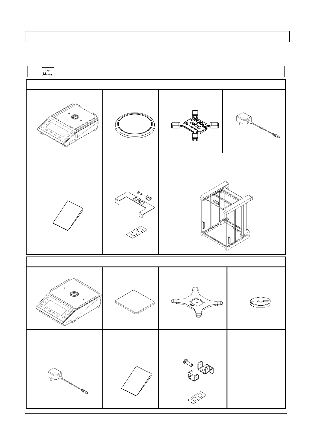
1-3 Check for the articles contained in the box
The package box contains the following;
If anything missing or broken should be found, please inform the store where you purchased the
product.
Sealing kit is already mounted on the verified balance.
Round pan type (MG-S322)
①
Main unit (Round): 1
②
Round pan: 1
③
Pan base (Round): 1
④
AC adapter: 1
⑤
Operation manual: 1
⑥
Sealing kit
(Wire sealing kit
and tamper-proof
stickers)
⑦
Windshield (Assembly type): 1
(Refer to “Appendix 7 Windshield assembly
instructions”)
Square pan type (MG-S1501, MG-S8200)
①
Main unit (Square): 1
②
Square pan: 1
③
Pan base (Square): 1
④
Pan base screw: 1
⑤
AC adapter: 1
⑥
Operation
manual: 1
⑦
Sealing kit
(Wire sealing kit and
tamper-proof stickers)
Page 16
1 Prior to use MG-S series operation manual
-6-
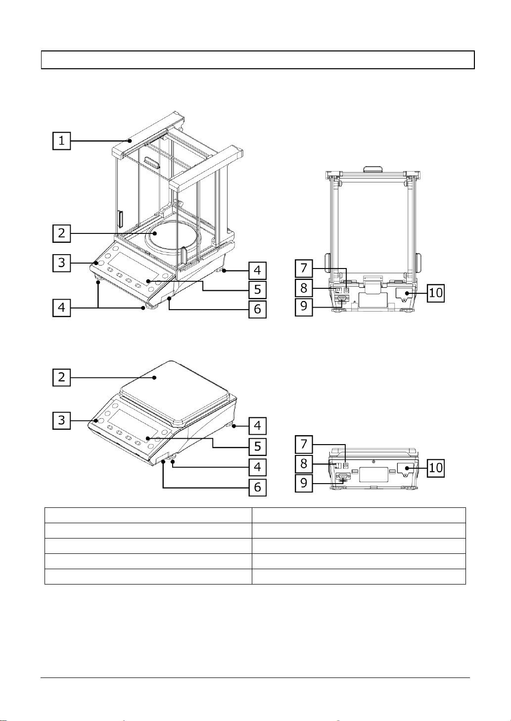
1-4 Name and function of each section
Round pan type (MG-S322)
Square pan type (MG-S1501, MG-S8200)
1
Windshield
2
Weighing pan
3
Level
4
Adjuster
5
Display
6
Battery case
7
AC adapter jack
8
USB connector (Type B)
9
RS-232C connector (D-sub 9 pin male)
10
Bluetooth module
Page 17
MG-S series operation manual 1 Prior to use
-7-
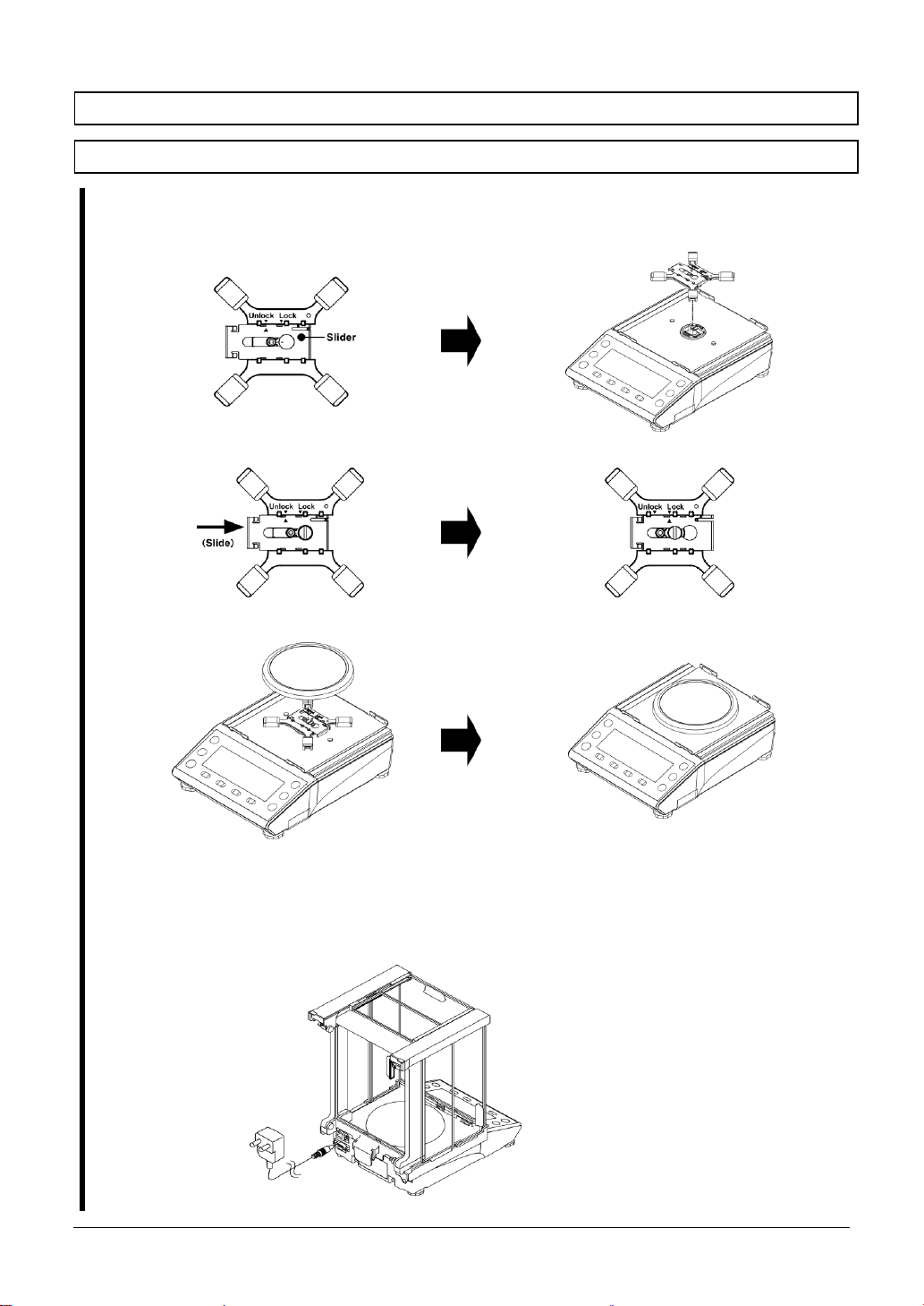
1-5 Assembling and installation of the product
1-5-1 Assembling the balance (Round pan type MG-S322)
1
Attach t he “Pan base”.
"Slider" to check that in the "Unlock” side, then attach to the balance.
2
Move the "Slider" to "Lock" side.
3
Mount the weighing pan.
4
Assemble the windshield.
Refer to “Appendix 7 Windshield assembly instructions” to assemble the windshield.
5
Connect the AC adapter.
Page 18
1 Prior to use MG-S series operation manual
-8-
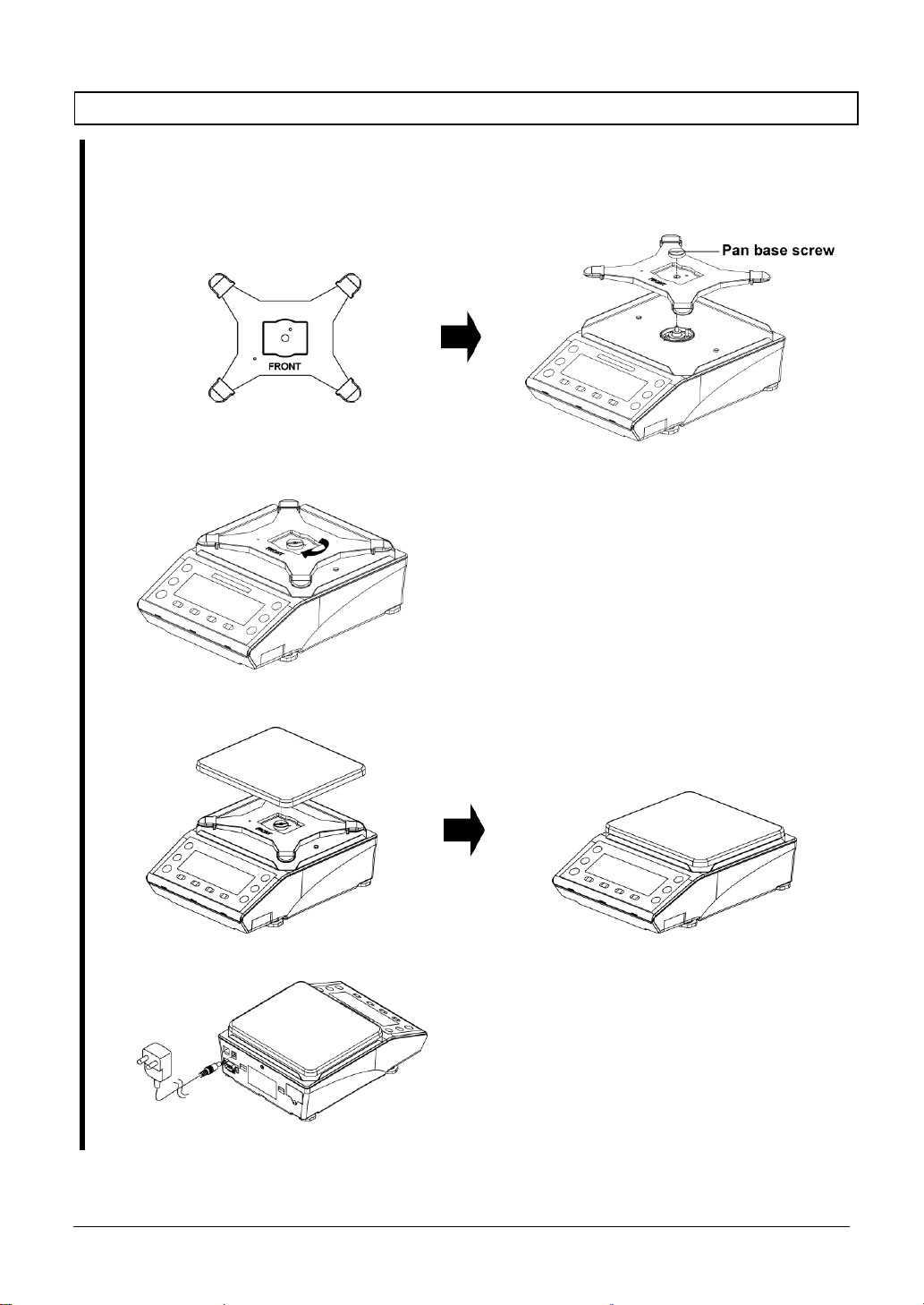
1-5-2 Assembling the balance (Square pan type MG-S1501, MG-S8200)
1
Attach t he “Pan base”.
(1) Direct "FRONT" to the display side.
(2) Attach to the balance, then turn the “Pan base screw” to fix.
2
Tight en the “Pa n ba se screw” firmly.
3
Mount the weighing pan.
4
Connect the AC adapter.
Page 19
MG-S series operation manual 1 Prior to use
-9-
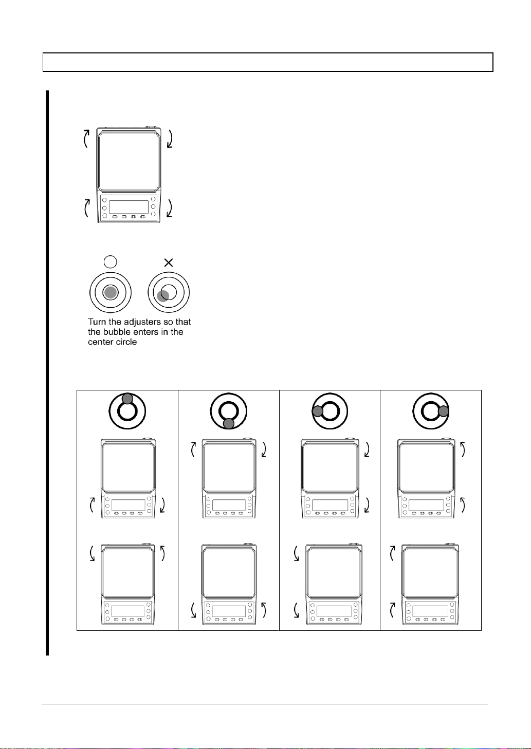
1-5-3 Level
1
Release the transportation lock of the
adjuster.
At the time of shipment, the adjusters provided
at the four corners of the bottom are locked.
Turn them in the direction shown in the figure on
the left to loosen them.
2
Level the balance.
(1)
While watching the level, turn the adjusters
provided on the bottom to level the main unit.
(2)
Bring the bubble enters in the center circle as
shown in the figure on the left.
(3)
When having leveled the main unit, slightly
push the four corners of the balance to make
sure that there is no rattle.
Turn the adjusters as shown below depending on the position of the bubble in the level.
or
or
or
or
Page 20
1 Prior to use MG-S series operation manual
-10-
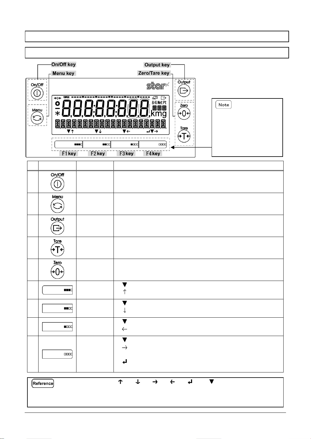
1-6 Description of the operation keys
1-6-1 Basic
No
Key
Name of key
Performance
1 [O n/Off]
Turns on and off the power for the balance.
On: Push the key, Off: Push the key long
2 [Menu]
Used for calling/exiting the setting menu.
Used for canceling the setting value selection and going back to the
measurering mode.
3 [Output]
Use for data outputting.
Use for data importing in the Statistics/Formulation mode.
4 [Tare]
Use for tare subtraction.
5 [Zero]
Use for zero-point adjustment.
6
[F1]
([F] key)
< < > > :
:
Use for selecting the mode, function and item.
Use for moving up to the menu/item selections, or use for
incrementing the numeric values.
7
[F2]
([F] key)
< <
> > : :
Use for selecting the mode, function and item.
Use for moving down to the menu/item selections, or use
for decrementing the numeric value.
8
[F3]
([F] key)
< <
> > : :
Use for selecting the mode, function and item.
Use for moving to the upper menu layer, or use for
selecting the digit to change.
9
[F4]
([F] key)
<
<
<
>
>
>
:
:
:
Use for selecting the mode, function and item.
Use for moving to the lower menu layer, or use for
selecting the digit to change.
Use for entering/executing the selected
menu/item/value, or use for returning to the setting
menu/measuring mode.
The [F] keys on which < >, < >, < >, < >, < > or < > are displayed above are
valid.
Shortcuts for various modes/functions can be assigned to [F] keys. Please refer to
“8-2 Shortcut setting for accessing various measuring modes” and “8-3 Free key setting”.
These keys are called [F]
keys or [F1]-[F4] key in
this manual as a matter of
convenience, while there
are not such indications
around them.
Page 21
MG-S series operation manual 1 Prior to use
-11-
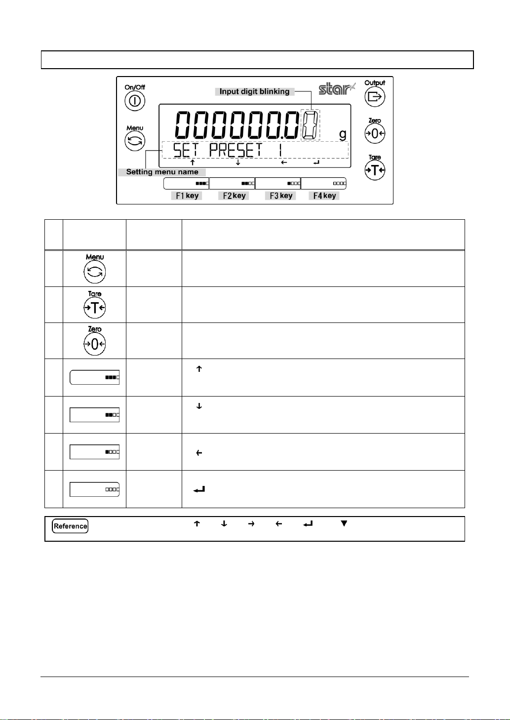
1-6-2 Setting value and numeric value inputting
No
Key
Name of
key
Performance
1 [Menu]
Cancel the input value and go back to the setting menu.
2 [Tare]
Input a decimal point < . > in “Specific Gravity mode”.
3 [Zero]
Use for changing polarity <+/->.
4
[F1]
([F] key)
< > : Use for incrementing the numeric values.
<0 → 1 → 2 →…→ 9 → 0>
5
[F2]
([F] key)
< > : Use for decrementing the numeric values.
<0 → 9 → 8 →…→ 1 → 0>
6
[F3]
([F] key)
< > : Use for selecting the digit to change.
7
[F4]
([F] key)
< > : Use for entering the value.
The [F] keys on which < >, < >, < >, < >, < > or < > are displayed above are
available.
Page 22
1 Prior to use MG-S series operation manual
-12-
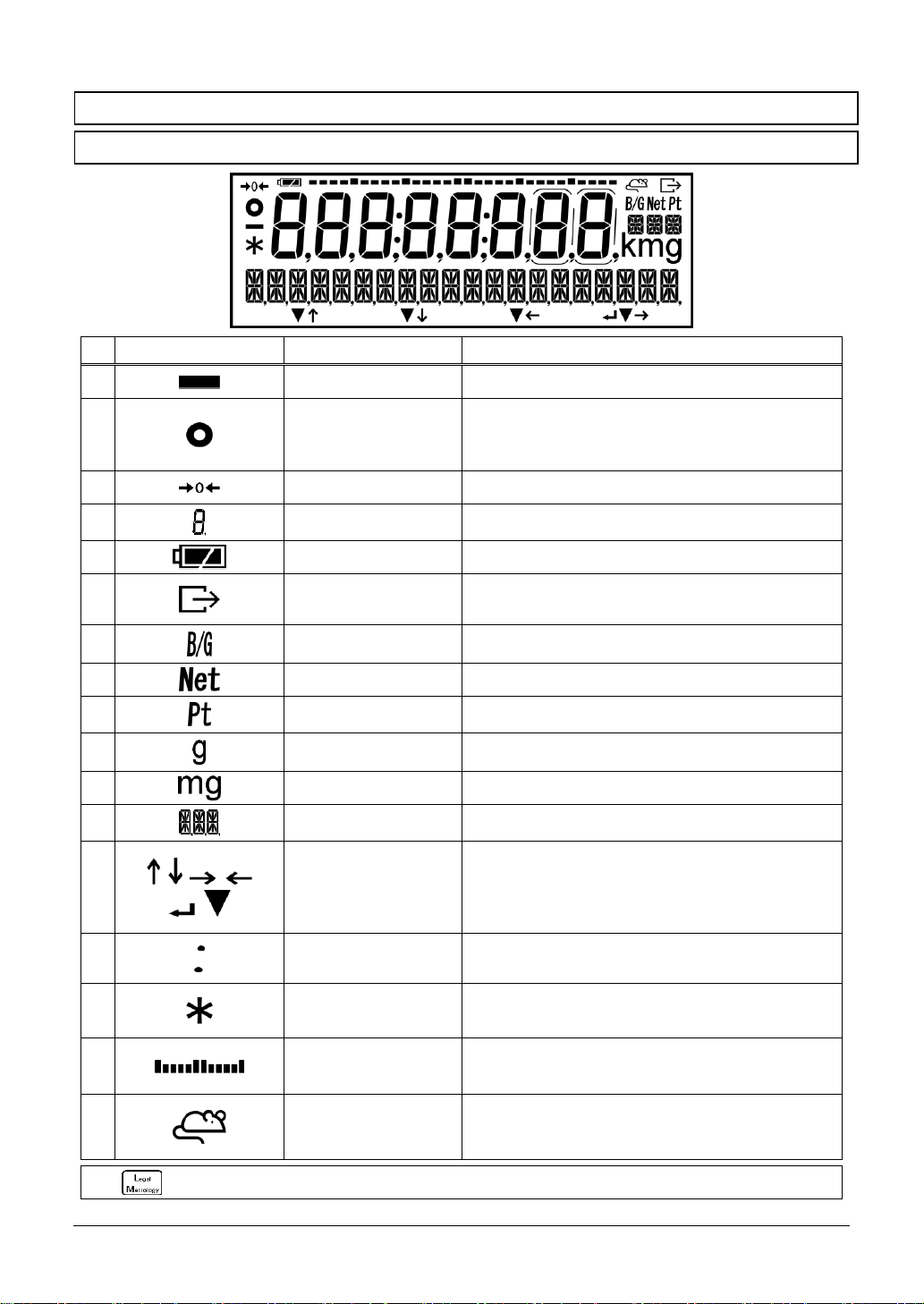
1-7 How to interpret the display
1-7-1 Description of segment.
No
Mark
Name
Description
1 Minus
Indicates the negative weight value and numeric.
2 Stable mark
-
-
When displayed: The balance is in the stable
condition.
When not displayed: The balance is not in the
stable condition.
3 Zero point
Indicates the zero point.
4 7 segment
- - Indicates the weight value
Indicates the simplified character.
5 Battery mark
Display when the balance is powered by batteries.
6 Output
Displayed when data are being output to external
devices.
7 Gross weight
Indicates gross weight.
8 Net weight
Indicates that the tare weight is being subtracted.
9 Preset tared weight
Indicates that the preset tare weight is being
subtracted.
10
Gram
Indicates the gram unit.
11 milligram
Indicates the milligram unit.
12
16 segment message
16 segment unit
- - Displays various messages.
Indicates the various units.
13
Operation of the [F]
key
Displayed when the [F1] – [F4] keys are effective.
14 Colon
Displayed when the date and time display.
15 Asterisk
- Lights in the standby status.
- Indicates addition available status when the
adding function is used.
16 Bar graph
Indicates the present total amount relative to the
weighing capacity defined as 100%.
17
Animal weighing
mode
Displayed when the animal weighing mode.
Nos. 9, 11 and 17 are not indicated on the verified balance.
Page 23
MG-S series operation manual 1 Prior to use
-13-
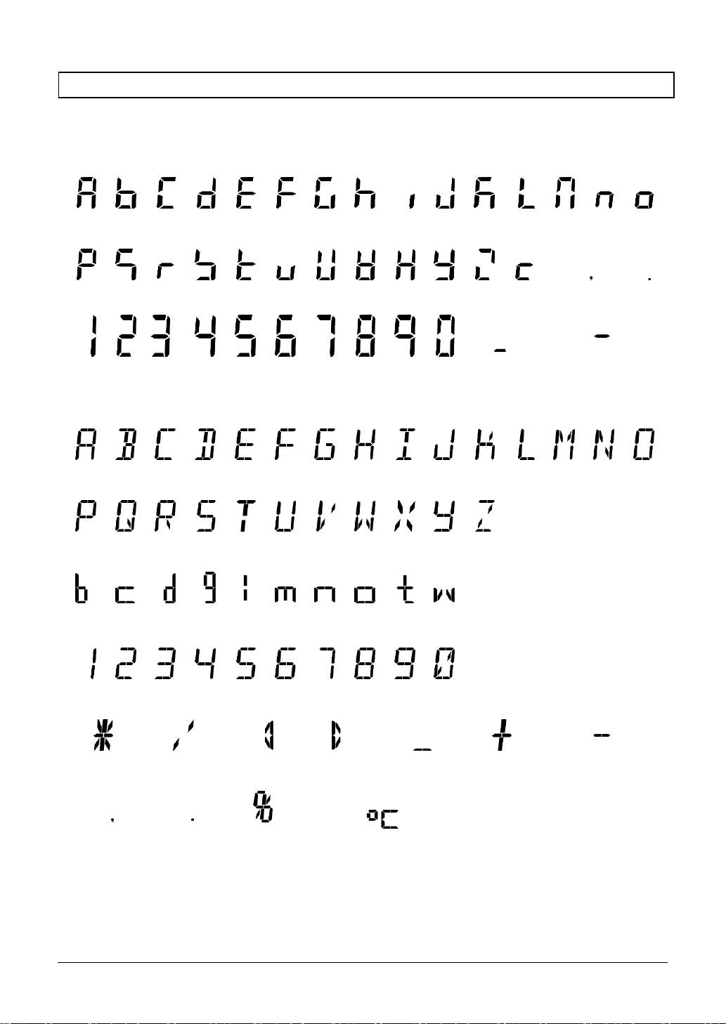
1-7-2 LCD character font
■7-segment
A B C D E F G H I J K L M N O
P Q R S T U V W X Y Z c comma
point
1 2 3 4 5 6 7 8 9 0 space
minus / hyphen
■16-segment
A B C D E F G H I J K L M N O
P Q R S T U V W X Y Z
b c d g l m n o t w
1 2 3 4 5 6 7 8 9
0
asterisk
slash
left arrow
right arrow
space
plus
minus / hyphen
comma
point
percent
Degree Celsius
Page 24
2 Basic usage MG-S series operation manual
-14-
2 Basic usage
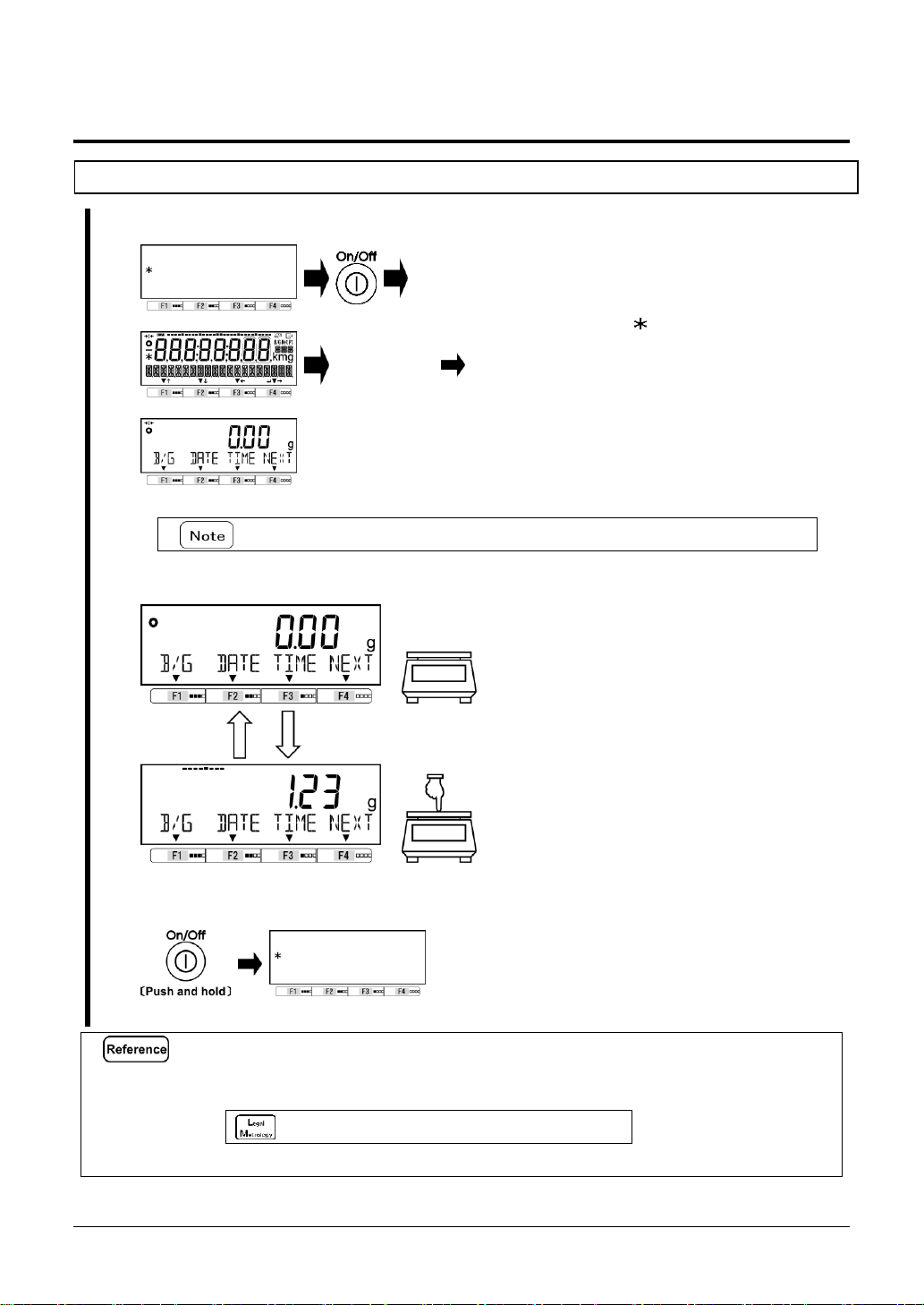
2-1 Turning on/off the power, and checking for the operation
1
Turn on the power for the balance.
“Self-check”
Connect the included AC adapter to the
balance.
When the AC adapter is plugged in, the
balance enters the standby state and an
asterisk < > appears.
Push [On/Off] key.
All displays on the LCD lights, followed by
the self-check of the balance. During the
self-check, the LCD display automatically
changes.
Completion of the self-check is followed by
the weight mode.
Do not push any key during the self-check.
2
Balance operation check.
Press the weighing pan lightly to check if
the indication changes.
3
Turn off the power for the balance.
Push and hold [On/Off] key (About 2
seconds)
(1)
Pushing and holding [On/Off] key obtains the standby status from any operation status.
(2)
When battery driven, the balance on/shutdowns without standby status.
(3)
The balance starts up in the last measuring mode before it was switched off.
Verified balance always starts up in weighing mode.
Page 25
MG-S series operation manual 2 Basic usage
-15-
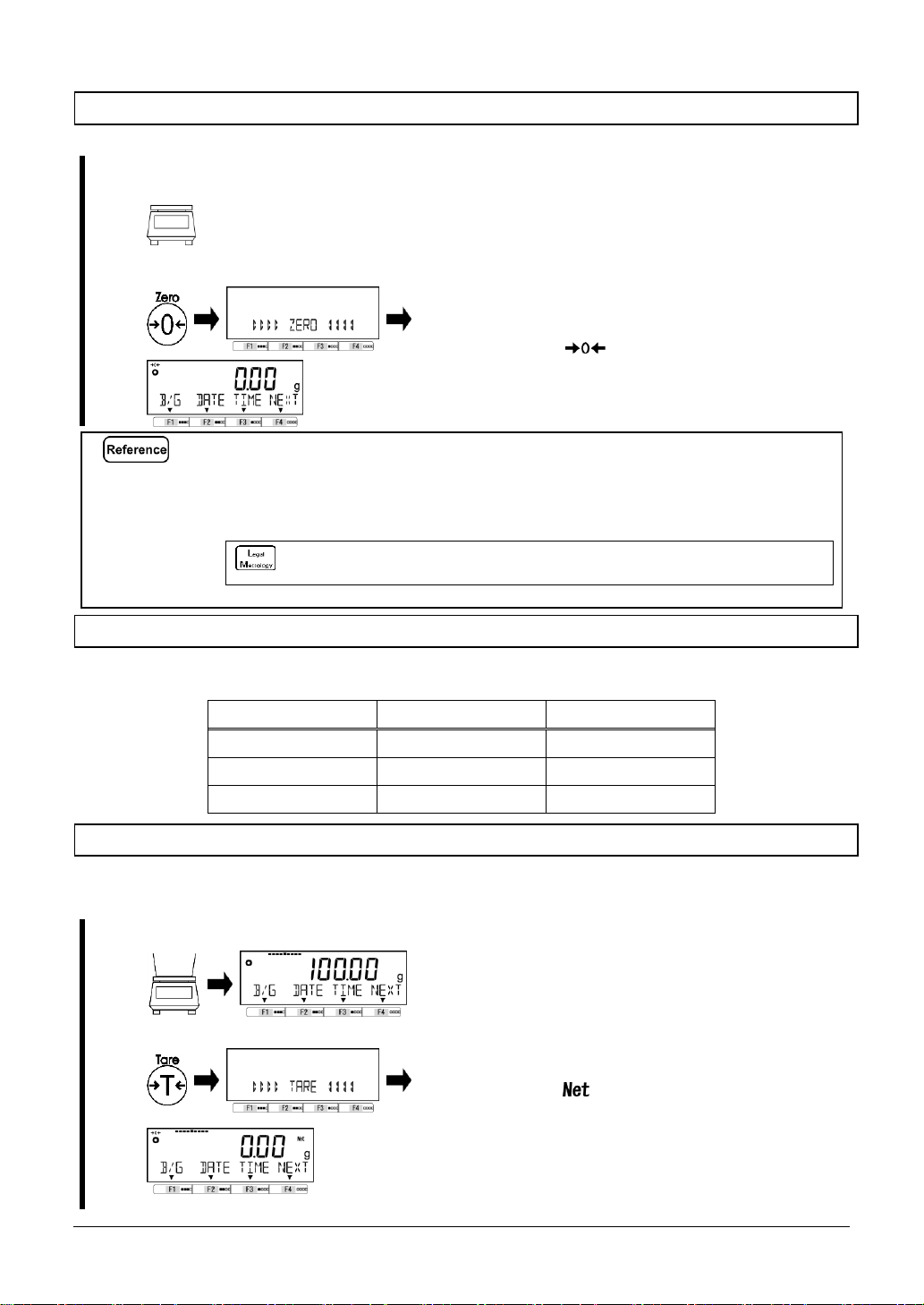
2-2 Zero-point adjustment
Adjusting the indication to zero is called "Zero-point adjustment".
1
Check the weighing pan.
Make sure that nothing is placed on the
weighing pan.
2
Execu te “Zer o-po int adjust ment”.
Push [Zero] key.
After the weight indication is stabilized, the
indication become zero and the symbol
“ ” lights.
(1)
Zero-point adjustment cannot not be performed when a sample whose weight is over the “Zero-
point adjustment range” is placed on the weighing pan. In that case, make the “tare” referring to
the “2-3 Weighing a sample placed on a container (tare)”
(2)
Stability waiting during the Zero-point adjustment can be set using the Setting menu
<17 WT STABLE>.
For verified balance, <17 WT STABLE> is not indicated and the balance always
wait stability during the zero-point adjustment.
2-2-1 Zero-point adjustment range
There is a Zero-point adjustment range (limit) in this product. When the weighing load (gross) exceeds
the upper or lower limit, “Zero-point adjustment” cannot be executed.
Model
Lower limit (g)
Upper limit (g)
MG-S322
-4.80
4.80
MG-S1501
-22.5
22.5
MG-S8200
-123
123
2-3 Weighing a sample placed on a container (tare)
When weighing a sample to be weighed with the object placed on a container (tare), the weight of the
container must be subtracted from the total weight to get the actual weight of the object to be weighed.
This is called “tare subtraction” or “tare”.
1
Place a container on the weighing pan.
The weight of the container is displayed.
2
Perform tare subtraction.
Push [Tare] key.
The indication changes to zero and the
< > symbol lights.
Page 26
2 Basic usage MG-S series operation manual
-16-
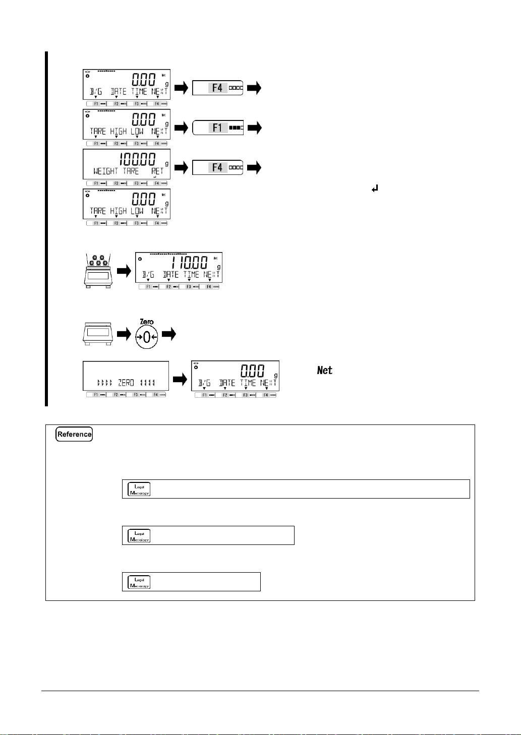
3
Check the tare weight.
The tare weight can be checked by operating
“Free keys” if the <TARE> is assigned to the
Free key.
Refer to “8 Controlling and adjustment
functions” for setting the Free keys.
Push [F4] key to switch the menu bar
and push [F1-F3] key on which <TARE>
is displayed above.
The tare weight is displayed on the display,
then push [F4] < > key to return to the
measuring mode.
4
Put the sample on the tare.
The net weight of the sample is displayed.
5
Clear the tare weight data.
Remove the sample and tare on the
weighing pan, then push [Zero] key.
Therefore, the indication becomes zero and
< > indication disappears.
(1)
Performing the tare narrows the weighing range as much as the amount
of the tare weight mass (tare weight).
Weighable range = weighing capacity - tare weight
(2)
Tare weight can be output at “3 Check the tare weight” by pushing [Output] key.
Check “External input/output functions” to refer the output setting.
(3)
Stability waiting during the tare can be set using the Setting menu <17 WT STABLE>.
The setting of <17 WT STABLE> is not changeable and the balance always wait
stability during tare-subtraction.
(4)
When using a tare whose tare weight is already known, the tare can be performed in advance by
inputting its tare weight (preset tare). For its setting method, refer to “5 User information setting”.
Preset tare function is not available.
(5)
When turning on the power placing a tare that exceeds the initial zero-adjustment range at the
time of power supply, the tare subtraction is executed.
This operation is not valid.
Page 27
MG-S series operation manual 2 Basic usage
-17-
2-4 Weighing the additional sample
Weigh the first sample and the additional sample separately.
1
Place a sample to be weighed.
The mass of the sample to be weighed placed is
indicated.
2
Perform the tare.
Push [Tare] key.
The indication changes to zero and the < >
symbol appears.
3
Place an additional sample to be
weighed.
The mass of the added sample alone is indicated.
2-5 Basic operation
Shortcuts for various modes/functions can be assigned to [F] keys. Please refer to
“8-2 Shortcut setting for accessing various measuring modes” and “8-3 Free key setting”.
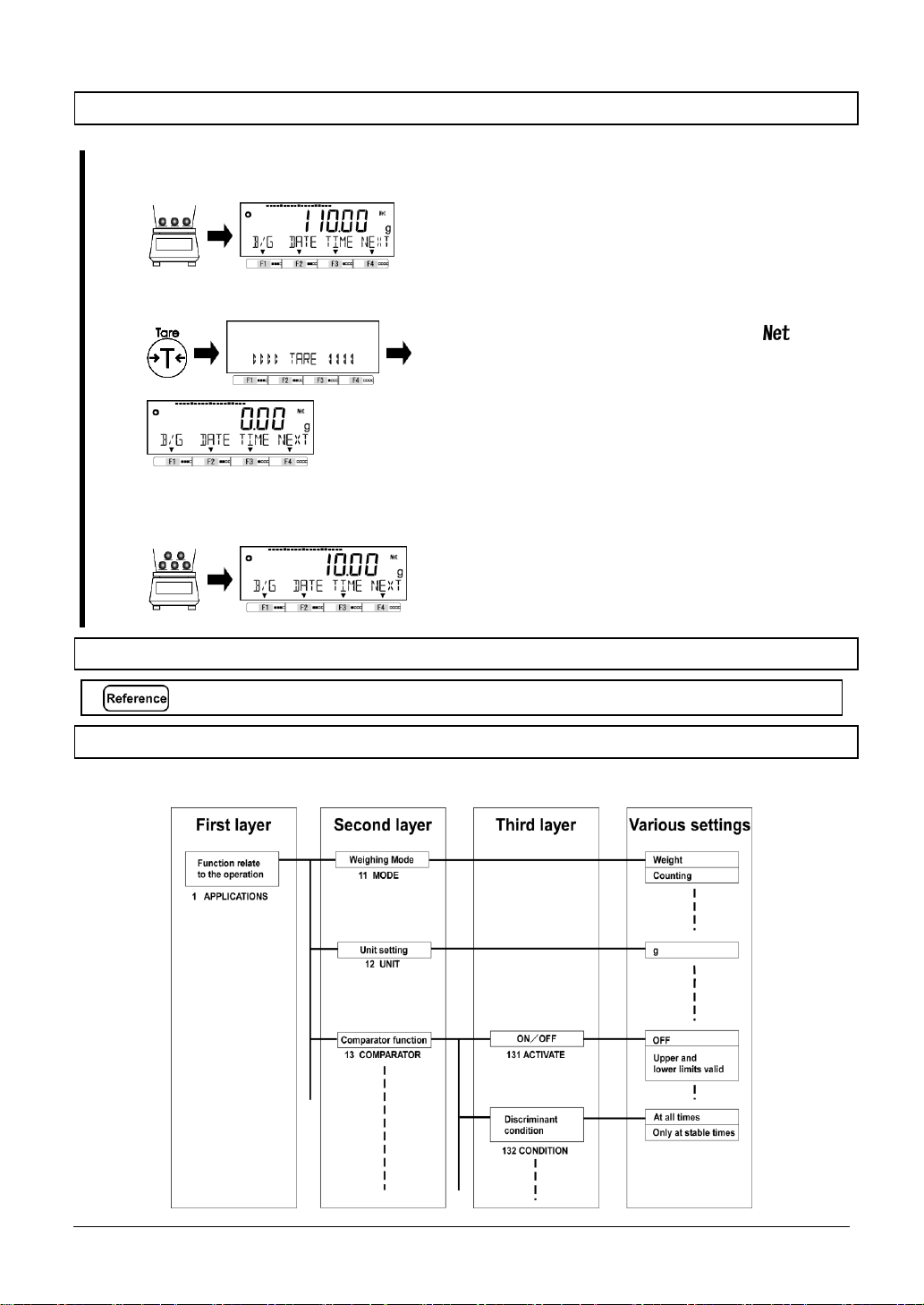
2-5-1 Hierarchy of a setting menu
The setting menu of this product is divided into four, from the first layer to the third layer and for various
setings.
Page 28
2 Basic usage MG-S series operation manual
-18-
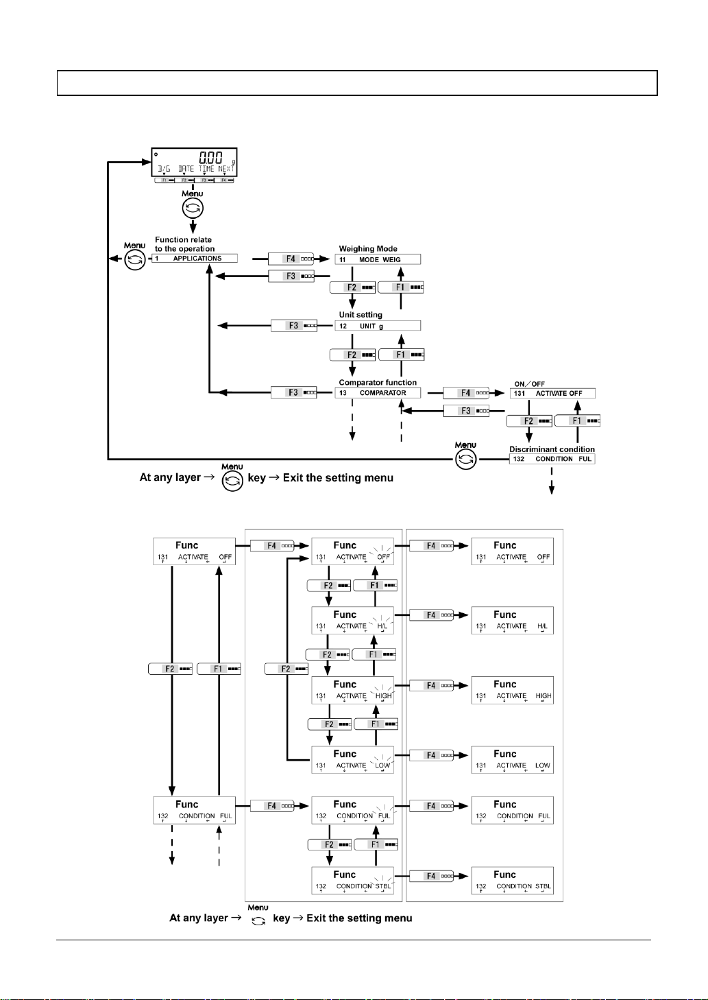
2-5-2 Operation of the setting menu
To perform settings for various functions from the state of weighing, chiefly execute the following
procedure.
■Go to the menu item to set
■Select the setting value and execute/fix.
Page 29
MG-S series operation manual 2 Basic usage
-19-
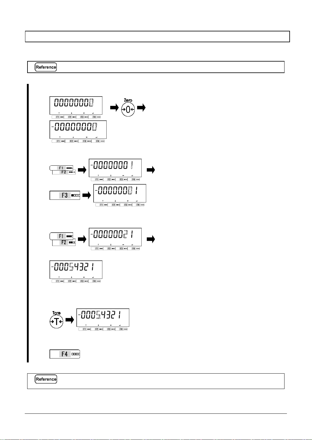
2-5-3 Numeric value input
Input upper/lower limit, reference weight, preset tare weight, coefficient, specific gravity of the media
liquid, water temperature, date/time and ID/password at each mode.
Numeric value inputting is limited to eight digits at a maximum.
e.g.) When inputting “-5.4321”.
1
Input “– “.
Push [Zero] key to change the polarity to
“-”.
2
Input “1 “.
The digit for inputting is blinking.
Push [F1, F2] key to
increment/decrement the digit to “1”.
Push [F3] key to input the next digit.
3
Input “2, 3, 4, 5 “ .
・・・
Input “2, 3, 4, 5” by the procedure above.
4
Input “.” .
Push [Tare] key to input “.” on the
immediately right of the blinking digit.
5
Fix the input value.
Push [F4] key to fix the input value.
“-5.4321” is saved on the balance.
“-” and “ . ” cannot be input in ID or Password setting.
cf. “8-5-1 Balance ID setting”
Page 30
2 Basic usage MG-S series operation manual
-20-
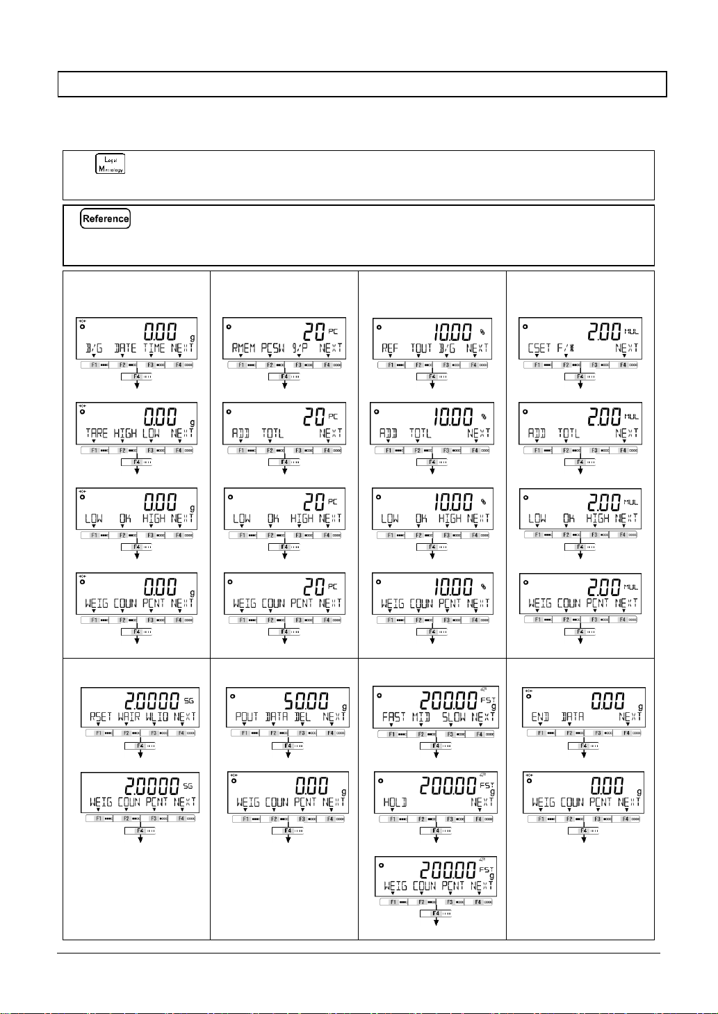
2-5-4 [ F ] key switching at each measuring mode
You can switch the measuring mode, or select and set the function, by operating the [F] keys at each
measuring mode.
This chapter shows the [F] keys switching by pushing the [F4] key.
Refer to “3 Function related to the operation” for the [F1-F3] keys operation.
For verified balance:
-
-
“Adding execution, Sum total” is not available;
“Multuplied by Coefficient mode”, “Statistics mode”, “Animal mode” and “Formulation mode” are
not available.
“"
(1)
In weighing mode, <<F1-F6>> (Free keys) are assigned to [F] keys as described follow;
<<F1>> and <<F4>>: [F1] key, <<F2>> and <<F5>>: [F2] key, <<F3>> and <<F4>>: [F3] key.
Please take care not to confuse <<F1-F4>> to [F1-F4] keys.
(2)
Refer to “8 Controlling and adjustment functions” for assigning “Free keys” and “Modes” to
[F] keys.
Weighing mode
Counting mode
Percentage mode
Multiplied by
Coefficient mode
<<F1-F3>> (Free key)
Counting mode menu
Percentage mode menu
Multiplied by coefficient
mode menu
<<F4-F6>> (Free key)
Adding execution, Sum total
Adding execution, Sum total
Adding execution, Sum total
Comparator setting menu
Comparator setting menu
Comparator setting menu
Comparator setting menu
Measuring mode switching
Measuring mode switching
Measuring mode switching
Measuring mode switching
Return to the first menu item
Return to the first menu item
Return to the first menu item
Return to the first menu item
Specific gravity mode
Statistics mode
Animal mode
Formulation mode
Specific gravity mode menu
Statistics mode menu
Animal mode menu
Formulation mode menu
Measuring mode switching
Measuring mode switching
Animal mode menu
Measuring mode switching
Return to the first menu item
Return to the first menu item
Measuring mode switching
Return to the first menu item
Return to the first menu item
Page 31

MG-S series operation manual 3 Functions related to the operation
-21-
3 Functions related to the operation
Settings to change the balance operations.
3-1 Hierarchy of functions related to the operation
For verified balance:
- Gray shaded items ( ) are not indicated;
- <17 WT STABLE> is not indicated and fixed to be <ON>;
- <141 ACTIVATE> is not indicated and fixed to be <OFF>;
- “grain” is not selectable on MG-S1501 and MG-S8200;
- “carat” is not selectable on MG-S8200.
Initial setting value of <12 UNIT> is:
- <g>(gram) on MG-S322, MG-S1501, and non-verified MG-8200;
- <LB>(pound) on verified MG-S8200.
★: Initial setting value in a verified balance
Page 32

3 Functions related to the operation MG-S series operation manual
-22-
3-2 Various measuring modes of the balance
Refer to “6 External input/output functions” to output the measuring data to other devices.
3-2-1 Weighing mode
Weighing mode is the basic mode for weighing.
Various functions can be used with weighing mode by pushing the “Free key”. Please refer to “8-3
Free key setting”.
1
Select the weighing mode.
Push [Menu] key, then push [F1-F4] keys
to go to <11 MODE>.
Push [F4] key to change the setting
value.
Push [F1/F2] key to select.
WEIG
:
Weighing mode
Push [F4] key to fix.
2
Exit the setting menu.
Push [Menu] key to shift to the weighing
mode.
3
Execute tare-subtraction
Place the container on the weighing pan if
necessary.
Push [Tare] key
Tare-subtraction is executed, then the
indication changes to zero and the
< > symbol lights.
4
Weigh the sample.
Place the weighed.
The weighing result is displayed.
Page 33

MG-S series operation manual 3 Functions related to the operation
-23-
3-2-2 Counting mode
Counting mode can count the number of items by placing the items for which sampling has been
completed on the balance and dividing the total weight of those items by the recorded unit weight.
(1)
When to use for prescription counting in USA, Class II unit shall be selected.
Class III units are not legal for trade for prescription counting.
Please refer to “Appendix 1-1 Basic Specification” for metrological specification in each weighing unit.
(2)
For verified balance:
- Numeric value setting method is not available;
- Measuring unit indication of pieces is “PC” instead of “PCS”.
The unit weight is inputted by following method:
-
Actual value setting method:
Place the specified number of samples on the balance to record the
average unit weight.
-
Numeric value setting method:
Input numeric value of the unit weight by key operation.
1
Select the Counting mode.
Push [Menu] key, then push [F1-F4]
keys to go to <11 MODE>.
Push [F4] key to change the setting
value.
Push [F1/F2] key to select.
COUN
:
Counting mode
Push [F4] key to fix.
2
Exit the setting menu.
Push [Menu] key to shift to the Counting
mode.
3-2-2 (1) Actual value setting method
Place the specified number of samples on the balance to record the average unit weight internally.
For verified balance:
-
-
-
-
Minimum sample size in pieces “MSS” is 10 PC;
<On 5> in Step 2 is not available;
1 to 9 PC cannot be selected on <on VAR>;
The unit weight (individual piece weight “MPW”) less than 3d and total sample weight
less than 30d cannot be adopted.
1
Select whether or not employ the previous
recorded unit weight.
Push [F3/F4] key to select whether or not
employ the previous data.
When there is no data record, this step is
skipped.
Push [F3/F4] key to select.
NO
:
Change
YES
:
Not Change
When <YES> is selected, go to step 6.
2
Select the “ number of samples mode” .
Place a container (tare) on the weighing pan if
necessary.
Push [F1/F2] key to select.
on 5
:
5 PC
on 10
:
10 PC
on 30
:
30 PC
on 50
:
50 PC
on 100
:
100 PC
on VAR
:
1 – 999 PC
PCSWGT
:
Numeric value setting method
See 3-2-2(2)
Push [F4] key to fix.
Tare-subtraction or zero-point adjustment is
executed automatically.
Page 34

3 Functions related to the operation MG-S series operation manual
-24-
3
Place the samples.
Place the set number of samples on the
container.
4
Record the unit weight.
Push [F4] key to fix.
The unit weight is recorded.
5
Simple SCS method (When enabled).
・・・
When <1C Simple SCS> is valid, Simple SCS
method is activated and the sample counting
indication blinks during this function.
Add more samples, then the number of
samples and unit weight is automatically
updated when the indication becomes stable.
The number of additional samples can be up to
two times the number of the samples of the
latest update.
For example, when “10 PC” is set, add 20 or
less samples.
Repeat this step until the number of the
samples has reached approximately one-fifth
to one-half of the total numbers that you are
intended to count.
Push [F4] key to fix the updated unit
weight.
6
Put samples in place to count them.
Place the samples.
Count result is displayed.
(1)
When <on VAR> is selected in step 2, select the specified number of the sample among 1 to 999
by operating [F1/F2] keys.
For verified balance, 1 to 9 PC cannot be selected on <on VAR>.
(2)
When simple SCS is operating, if the weight of the samples is less
than the “SCS weight” ― 99 times of the minimum readability
(d x 99) ―, <Add> blinks on the display and unit weight cannot be
updated.
In this case, add samples until <Add> indication disappears, or select
the larger number of samples in step 2.
Model
Readability d (g)
SCS weight (g)
MG-S322
0.01
0.99
MG-S1501
0.1
9.9
MG-S8200
1
99
(3)
When simple SCS is operating, if the number of the additional
samples is larger than two times of the sample number of latest
update, <Sub> blinks on the display and unit weight cannot be
updated.
In this case, decrease the number of additional samples.
Page 35

MG-S series operation manual 3 Functions related to the operation
-25-
3-2-2 (2) Numeric value setting method
Input numeric value of the unit weight by key operation.
This moethod is not available for verified balance.
1
Select whether or not employ the previous
recorded unit weight.
Push [F3/F4] key to select whether or
not employ the previous data.
When there is no data record, this step is
skipped.
Push [F3/F4] key to select.
NO
:
Change
YES
:
Not Change
When <YES> is selected, go to step 4.
2
Select the “ unit weight va lue input mode”.
Push [F1/F2] key to select.
PCSWGT
:
Unit weight value input
Push [F4] key to fix.
3
Input the unit weight.
Numeric value input
(Refer to “2-5-3 Numeric value input”)
Input the unit weight.
Push [F4] key to fix.
4
Put samples in place to count result.
Place a container (tare) on the weight pan.
Push [Tare] key.
Place the samples.
The count result is displayed.
Page 36

3 Functions related to the operation MG-S series operation manual
-26-
3-2-2 (3) Switching the display at Counting mode
1
Push [F1-F4] keys to switch the display.
For non
<ADD> and <TOTL> can be used when <14 ADDITION> is activated.
For
Page 37

MG-S series operation manual 3 Functions related to the operation
-27-
3-3 Percentage mode
The weight of a sample to be weighed is indicated in percent relative to the reference weight.
There are two methods to input the reference weight;
-
Actual value setting method ([onW]):
Place the reference weight on the balance to record the
weight.
-
Numeric value setting method ([NUM]):
Input numeric value of the reference weight by key
operation.
(1)
Weight limit.
Models
d (g)
Weight limit (g)
MG-S322
0.01
0.10
MG-S1501
0.1
1.0
MG-S8200
1
10
(2)
The minimum percent to be displayed is automatically set according to the recorded reference
weight.
Readability (%)
Range of reference weight
1
Lower weight limit
<=
Reference weight
<
Lower weight limit X 10
0.1
Lower weight limit X 10
<=
Reference weight
<
Lower weight limit X 100
0.01
Lower weight limit X 100
<=
Reference weight
1
Select the percentage mode.
Push [Menu] key, then push [F1-F4] keys to go
to <11 MODE>.
Push [F4] key to change the setting value.
Push [F1/F2] key to select.
PCNT
:
Percentage mode
Push [F4] key to fix.
2
Exit the setting menu.
Push [Menu] key to shift to the percentage
mode.
3
Select whether or not employ the
previous recorded reference value.
Push [F3/F4] key to select whether or not
employ the previous data.
When there is no data record, this step is skipped.
Push [F3/F4] key to select.
NO
:
Change
YES
:
Not Change
When <YES> is selected, go to step 6.
4
Select the method of setting the
reference value.
Push [F3/F4] key to select.
onW
:
Actual value
NUM
:
Numeric value
Page 38

3 Functions related to the operation MG-S series operation manual
-28-
5
Save the reference value.
In the case of [onW].
Place the reference weight on the balance.
Push [F4] key to record.
In the case of [NUM].
Numeric value input
(Refer to “2-5-3 Numeric value input”)
Input the reference value.
Push [F4] key to fix.
6
Weigh the samples.
The ratio of the weight of the sample to the reference
weight is indicated in percent.
Page 39

MG-S series operation manual 3 Functions related to the operation
-29-
3-3-1 Switching the display at percentage mode
1
Push [F1-F4] keys to switch the display.
For non
<ADD> and <TOTL> can be used when <14 ADDITION> is activated.
For
Page 40

3 Functions related to the operation MG-S series operation manual
-30-
3-4 Multiplied by Coefficient mode
Measured weight is multiplied by the preset coefficient, and the result be displayed.
This mode is not available for verified balance.
1
Select the Multiplied by Coefficient mode.
Push [Menu] key, then push [F1-F4]
keys to go to <11 MODE>.
Push [F4] key to change the setting
value.
Push [F1/F2] key to select.
MULT
:
Multiplied by Coefficient mode
Push [F4] key to fix.
2
Exit the setting menu.
Push [Menu] key to shift to the
Multiplied by Coefficient mode.
3
Select whether or not employ the previous
recorded coefficient.
Push [F3/F4] key to select whether or
not employ the previous data.
When there is no data record, this step is
skipped.
Push [F3/F4] key to select.
NO
:
Change
YES
:
Not Change
When <YES> is selected, go to step 6.
4
Set the coefficient.
Numeric value input
(Refer to “2-5-3 Numeric value input”)
Input the coefficient.
Push [F4] key to fix.
5
Weigh the samples.
The weight of the sample is multiplied by the
coefficient and the result is displayed.
Page 41

MG-S series operation manual 3 Functions related to the operation
-31-
3-4-1 Switching the display at Multiplied by Coefficient
1
Push [F1-F4] keys to switch the display.
<ADD> and <TOTL> can be used when the <14 ADDITION> is activated.
Page 42

3 Functions related to the operation MG-S series operation manual
-32-
3-5 Specific gravity mode
In the specific gravity mode, the ratio of the density of a substance to the density of water at its densest
(4°C) for liquids is calculated.
Specific gravity mode is NOT legal for trade.
Purchase the optional “specific gravity measurement kit” or prepare the equipments ― a water tank,
hanging string/wire, net/basket for placing the sample, thermometer etc.― in accordance with the
samples to be measured.
When purchased with “specific gravity measurement kit”, please refer to the option’s manual.
Procedure to measure the specific gravity:
1.
Prepare the equipments or specific gravity measurement kit
2.
Input the water temperature or the specific gravity of the reference liquid.
3.
Measure the sample weight in the air.
4.
Compensate the buoyancy acting on the net/basket.
5.
Measure the sample weight in the water/liquid.
6.
The specific gravity of the sample is displayed.
1
Select the specific gravity mode.
Push [Menu] key, then push [F1-F4]
keys to go to <11 MODE>
Push [F4] key to change the setting
value.
Push [F1/F2] key to select.
SPGR
:
specific gravity mode
Push [F4] key to fix.
2
Exit the setting menu.
Push [Menu] key to shift to the specific
gravity mode.
3
Select the reference liquid.
Push [F3/F4] key to select the reference
liquid.
OTHER
:
Liquid other than water
H20
:
water
4
Input the specific gravity of the reference
liquid or the temperature of the water.
<OTHER>: Liquid other than water
Numeric value input
(Refer to “2-5-3 Numeric value input”)
Enter the specific gravity of the
reference liquid and push [F4] key to fix.
<H20>: Water
Numeric value input
(Refer to “2-5-3 Numeric value input”)
Enter the temperature of the water and
push [F4] key to fix.
Page 43

MG-S series operation manual 3 Functions related to the operation
-33-
5
Measure the sample weight in the air.
Set the net/basket on the balance and
push [Tare] key.
Load the on the net/basket to measure
the weight of the sample in the air, then
push [F4] key to record it.
6
Compensate the buoyancy acting on the
net/basket.
Remove the sample on the net/basket
and push [Tare] key to tare, then sink
the net/basket into the water/liquid.
Push [Tare] key to compensate the
buoyancy acting on the net/basket.
7
Measure the sample weight in the
water/liquid.
Put the sample on the net/basket in the
water/liquid, then push [F4] key to
record.
The specific gravity of the sample (for the
4°C water) is automatically calculated and
displayed.
3-5-1 Switching the display at “Specific gravity mode”
1
Push [F1-F4] keys to switch the display.
Page 44

3 Functions related to the operation MG-S series operation manual
-34-
3-6 Statistics mode
The statistical operation function collects weight data and indicates maximum, average, and other
statistical values.
This mode is not available for verified balance.
(1)
Only “mg” or “g” can be used.
(2)
Each calculation result except “CV” follows the smallest readability among which are used to
record the weighing data.
(3)
Up to 999 weight data can be saved.
The output timing is fixed to “Once at stable/immediately after [Output] key is pushed” regardless
of the setting value of <413/423 CONDITION> of “6 External input/output function”.
The setting of <17 WT STABLE>
The output condition
ON
Once at stable after [Output] key is pushed
OFF
Once immediately after [Output] key is pushed
1
Select the statistics mode.
Push [Menu] key, then push [F1-F4] keys to
go to <11 MODE>.
Push [F4] key to change the setting value.
Push [F4] key to select.
STAT
:
Statistics mode
Push [F4] key to fix.
2
Exit the setting menu.
Push [Menu] key to shift to the statistics
mode.
3
Choose whether or not clear all the
data.
Push [F3/F4] key to select whether or not
clear all the data.
When there is no data stored, this step is skipped.
YES
:
Clear
NO
:
Not clear
When <NO> is selected, weighing step of the next
statistics data starts.
4
Store weighing data.
Place the sample in the weighing pan.
Push [Output] key to store the sample weight.
Weighing data is collected and then output.
Page 45

MG-S series operation manual 3 Functions related to the operation
-35-
5
Collect more weighing data.
Store data in the same way as in step 4.
Repeat placing samples, storing data, and
removing the samples until the required number of
data items are collected.
6
Display the statistical operation result.
・・・
Push [F2] key (<DATA>).
The display changes to the statistical operation
display
Push [F1/F2] key to switch to another
calculated item.
Sum total
Maximum value
Minimum value
Range (Max – Min)
Average value
Standard deviation
Coefficient of variation
3-6-1 Switching the display at “Statistics mode”
1
Push [F1-F4] keys to switch the display.
Page 46

3 Functions related to the operation MG-S series operation manual
-36-
3-7 Animal mode
The balance can accurately weigh animals and other samples that move during measurement.
Even when animals and other samples move during measurement, when weight variations fit within the
set value range, the indication is held (hold) and the measurement result can be read.
This mode is not available for verified balance.
(1)
When the external output is activated, the output condition is fixed as following;
- Output once after the indication is held except when the <HOLD> is pushed
(step 5-b).
- Output once after the [Output] key is pushed during the indication is held.
(2)
Only “g” can be used.
1
Select the animal mode.
Push [Menu] key, then push [F1-F4]
keys to go to <11 MODE>.
Push [F4] key to change the setting
menu.
Push [F1/F2] key to select.
ANIM
:
Animal mode
Push [F4] key to fix.
2
Exit the setting menu.
Push [Menu] key to shift to the
animal mode.
3
Select the activity level .
Push [F1-F3] keys to select.
FAST
:
Wild
MID
:
In-between
SLOW
:
Quiet
4
Execute tare-subtraction
Place the container on the weighing pan.
Push [Tare] key
Tare-subtraction is executed, then the
indication changes to zero and the
< > symbol lights.
Page 47

MG-S series operation manual 3 Functions related to the operation
-37-
5
a) Weigh the animal.
Place the animal on the weighing pan.
After the weight variations fit within the
set range, the weighing indication is held
and < > indication appears.
b) When the animal is too wild, weigh the
animal using manual <HOLD> key.
Push [F4] <NEXT> key to display the
<HOLD> menu on [F1] key.
Place the animal on the weighing pan.
Push [F1] <HOLD> key, then the
weighing indication is held and
< > indication appears.
6
Remove the animal.
Remove the animal, then automatically
tare subtracted.
Page 48

3 Functions related to the operation MG-S series operation manual
-38-
3-8 Formulation mode
“Formulation mode” can store and refer the weight of each component compounded.
This mode is not available for verified balance.
(1)
Only “mg” or “g” can be used.
(2)
Up to 30 components can be stored.
(3)
“Preset tare function” cannot be used.
The output timing is fixed to “Once at stable/immediately after [Output] key is pushed” regardless
of the setting value of <413/423 CONDITION> of “6 External input/output function”.
The setting of <17 WT STABLE>
The output condition
ON
Once at stable after [Output] key is pushed
OFF
Once immediately after [Output] key is pushed
1
Select the formulation mode.
Push [Menu] key, then push [F1-F4]
keys to go to <11 MODE>.
Push [F4] key to change the setting
value.
Push [F1/F2] key to select.
FORM
:
Formulation mode
Push [F4] key to fix.
2
Exit the setting menu.
Push [Menu] key to shift to the
Formulation mode.
3
Choose whether or not clear all the data.
Push [F3/F4] key to select whether or
not clear the data. When there is no
data stored, this step is skipped.
<YES>
:
Clear
<NO>
:
Not clear
When <NO> is selected, weighing step of
the next component starts.
4
Zero point adjust.
Make sure that nothing is placed on the
weighing pan, then push [Zero] key.
Displays become zero and the symbol
“ ” lights.
5
Store the tare weight.
Load the tare and push [Tare] key to
store the tare weight.
Page 49

MG-S series operation manual 3 Functions related to the operation
-39-
6
Store the sample weight.
Put the sample on the tare and push
[Output] key to store the sample
weight.
Repeat the step 6 for all the samples to be
compounded.
When to set the tare individually for each
sample, repeat steps 4-6.
3-8-1 Check the stored data of each component
1
Push [F1-F4] keys to check the weight of each component.
Page 50

3 Functions related to the operation MG-S series operation manual
-40-
3-9 Unit setting
Various units can be selected. Please also refer to "Appendix 1-1 Basic specifications" and "Appendix 3
Unit indication and conversion table".
For verified balance, selectable measuring units are limited to:
- MG-S322: “gram”, “carat”, “pound”, “ounce” and “grain”;
- MG-S1501: “gram”, “carat”, “pound” and “ounce”;
- MG-S8200: “gram”, “pound” and “ounce.”
“”
1
Select the unit setting.
Push [Menu] key, then push [F1-F4] keys
to go to <12 UNIT>.
Push [F4] key to change the setting value.
Push [F1/F2] key to select the unit (Refer
to Unit Setting Menu List).
Push [F4] key to fix.
Unit Setting Menu List
mg
:
milligram
g
:
gram
ct
:
carat
LB
:
pound
OZ
:
ounce
OZT
:
troy ounce
GN
:
grain
DWT
:
pennyweight
MOM
:
momme
MSG
:
mesghal
TLH
:
Hong Kong tael
TLT
:
Taiwan tael
TLS
:
Singapore, Malaysia tael
TOLA
:
tola
BAT
:
baht
2
Exit the setting menu.
Push [Menu] key to shift to the measuring
modes.
3-10 Comparator function
It is possible to preset threshold values (limits) and determine whether or not a measured value is
within the range defined by the preset values.
The comparator function can be used in Weighing mode, Percentage mode, and Counting mode.
3-10-1 How to perform discrimination
Set the lower and the upper limits. Then, whether the weight of a sample to be weighed is “LOW”
(lower than the lower limit), “OK” (appropriate) or “HIGH” (higher than the upper limit), is indicated on
the LCD with “16-segment messages”.
16-segment messages
Discrimination
Single point setting
(lower limit)
Single point setting
(upper limit)
Two-point setting
(upper and lower limits)
Over the upper limit
< >
Blinking
< >
Blinking
< >
Blinking
Appropriate amount
< >
Blinking
< >
Blinking
< >
Blinking
Below the lower limit
< >
Blinking
< >
Blinking
< >
Blinking
The discrimination is performed according to the following criteria:
-
Absolute value:
The discrimination is performed based on the upper and lower limit values that have
been set in advance.
-
Relative value:
A reference numeric value is set in advance, and the discrimination is performed
based on the range defined by the upper and lower limit values that have been set
for the reference numeric value.
(For example)
Two-point (upper and lower limits) setting, Reference value = 1000.0g,
Lower limit value = 900.0 g, Upper limit value = 1200.0 g
Discrimination
method
Reference value
Lower limit value
Upper limit value
1000.0 g
900.0 g
1200.0 g
Absolute value 900.0 g
1200.0 g
Relative value
1000.0 g
-100.0 g
200.0 g
Page 51

MG-S series operation manual 3 Functions related to the operation
-41-
3-10-2 Comparator function setting
For the setting of the reference value and upper and lower limit values, refer to “5 User
information setting”.
1
Select the comparator function.
Push [Menu] key, then push [F1-F4] keys to
go to <131 ACTIVATE>
Push [F4] key to change the setting value.
Push [F1/F2] key to select.
OFF
:
OFF
H / L
:
Upper and lower limits valid
HIGH
:
Upper limit alone valid
LOW
:
Lower limit alone valid
Push [F4] key to fix.
2
Select the discriminant condition.
Push [F1-F4] keys to go to
<132 CONDITION>
Push [F4] key to change the setting value.
Push [F1/F2] key to select.
FULL
:
At all times
STBL
:
Only at stable times
Push [F4] key to fix.
3
Select the discriminant range.
Push [F1-F4] keys to go to
<133 RANGE>
Push [F4] key to change the setting value.
Push [F1/F2] key to select.
5
:
+5 d or more
50
:
+50 d or more
FULL
:
Entire area
Push [F4] key to fix.
4
Select the discriminant method.
Push [F1-F4] keys to go to
<134 METHOD>
Push [F4] key to change the setting value.
Push [F1/F2] key to select.
ABSOL
:
Absolution value method
RELAT
:
Relative value method
Push [F4] key to fix.
Page 52

3 Functions related to the operation MG-S series operation manual
-42-
3-11 Adding function
Weigh a plurality of samples to be weighed in sequence and indicates its total value.
The adding function includes two ways of calculating method.
This function is not available for verified balance.
The adding function can be used in Weighing mode, Percentage mode, Counting mode, and
Multiplied by Coefficient mode.
1
Select the adding function.
Push [Menu] key, then push [F1-F4] keys to
go to <141 ACTIVATE>
Push [F4] key to change the setting value.
Push [F1/F2] key to select.
OFF
:
Invalid
ON
:
Valid
Push [F4] key to fix.
2
Select the adding operation.
Push [F1-F4] keys to go to
<142 OPERATION>
Push [F4] key to change the setting value.
Push [F1/F2] key to select.
TOTAL
:
Addition accumulated
NET
:
Net addition
Push [F4] key to fix.
3
Select the adding direction.
Push [F1-F4] keys to go to
<143 DIRECTION>
Push [F4] key to change the setting value.
Push [F1/F2] key to select.
PLUS
:
Plus side addition
MINUS
:
Minus side addition
Push [F4] key to fix.
4
Set the “Free k e y”.
Set the following function to the <<F1-F6>> (Free
keys).
<62* F* KEY ADD>
:
Adding execute
<62* F* KEY TOTL>
:
Total indication
(Refer to “8 Controlling and adjustment functions”
for setting the free keys.)
Step 4 is required only when you are using an adding function on the weighing mode.
-
Method of weighing samples to be weighed while replacing the samples:
Addition accumulating
function.
-
Method of weighing samples to be weighed without replacing the samples:
Net adding function.
Page 53

MG-S series operation manual 3 Functions related to the operation
-43-
3-11-1 Weighing by means of the plus side addition
When <<ADD>> is assigned to [F1] key and <<TOTL>> is assigned to [F2] key.
1
Place a first sample to be weighed.
Place a first sample to be weighed.
After < > appears, push
[F1](<<ADD>>) key.
The weighed value is stored and <SUM
TOTAL> is indicated for a few seconds.
2
In the case of the addition accumulating
Replace a sample to be weighed with a new
one.
Remove the previous sample to be
weighed to return the indication to zero
and then place the next sample to be
weighed.
After < > appears, push
[F1](<<ADD>>) key.
The weighed value is stored and <SUM
TOTAL> is indicated for a few seconds.
Repeat this operation to perform addition.
In the case of the net addition
Add a sample to be weighed.
The indication automatically returns to
zero. Then add the next sample to be
weighed.
After < > appears, push
[F1](<<ADD>>) key.
After indicating <SUM TOTAL> and the
accumulated value for a few seconds, the
balance returns to the weight indication,
followed by the automatic tare.
Repeat this operation to perform addition.
3
Indicate the total value.
Push [F2](<<TOTL>>) key.
Total value is indicated.
4
Delete the total value.
Push [F3](<DEL>) key.
The total value is deleted.
Page 54

3 Functions related to the operation MG-S series operation manual
-44-
3-11-2 Weighing by means of the minus side addition
When <ADD> is assigned to [F1] key and <TOTL> is assigned to [F2] key.
1
Place a sample to be weighed.
Place a sample to be weighed.
Push [Tare] key.
2
In the case of the addition accumulating
Remove the sample to be weighed and
perform adding.
Remove the sample to be weighed.
After < > appears, push
[F1](<<ADD>>) key.
The weighed value is stored and <SUM
TOTAL> is indicated for a few seconds.
Repeat this operation to perform addition.
In the case of the net addition
Remove the sample.
Remove the sample to be weighed.
After < > appears, push
[F1](<<ADD>>) key.
After indicating <SUM TOTAL> and the
accumulated value for a few seconds, the
balance returns to the weight indication,
followed by the automatic tare.
Repeat this operation to perform addition.
3
Indicate the total value.
Push [F2](<<TOTL>>) key.
Total value is indicated.
4
Delete the total value.
Push [F3](<DEL>) key.
The total value is deleted.
Page 55

MG-S series operation manual 3 Functions related to the operation
-45-
3-12 Tare-subtraction reminder function
When the “tare-subtraction reminder” is activated, <PUSH TARE> alert is displayed when the tare
(container) is loaded.
When the zero-point-adjustment reminder operates at the same time, the zero-point adjustment
reminder has priority.
There are two modes in the tare-subtraction reminder function;
(1)
1 (Mode 1):
<PUSH TARE> is indicated when the weighing indication is over the zero-point-
adjustment range.
(2)
2 (Mode 2):
<PUSH TARE> is indicated when the weighing indication is over the zero-point-
adjustment range before tare subtraction, and when the net indication is negative
after tare subtraction.
1
Select the “ tare -subtraction reminder
funct ion ”.
Push [Menu] key, then push [F1-F4] keys to
go to <15 T REMINDER>.
Push [F4] key to change the setting menu.
Push [F1/F2] key to select.
OFF
:
Invalid
1
:
Activate the “Mode 1”
2
:
Activate the “Mode 2”
Push [F4] key.
2
Exit the setting menu and operate with
“tare -subtra cti on remi nder funct ion” .
Push [Menu] key to exit the setting menu.
Place a tare (container) on the weighing pan,
then <PUSH TARE> alert is displayed.
The alert disappears after [Tare] key is pushed
and tare-subtraction is completed.
Therefore, the indication becomes zero and
< > indication appears.
Page 56

3 Functions related to the operation MG-S series operation manual
-46-
3-13 Zero-point-adjustment reminder function
When the “zero-point-adjustment reminder” is activated, <PUSH ZERO> alert is displayed when the
load return to within the “zero-point adjustment range” after the load is once over the range.
1
Acti vate th e “z ero -point-adjustment
remin der”.
Push [Menu] key, then push [F1-F4]
keys to go to <16 Z REMINDER>, and
then push [F4] key to change the setting.
Push [F1/F2] key to select activate or
disable the function.
OFF
:
Disable
ON
:
Activate
Push [F4] key to fix.
2
Exit the setting menu and operate with
“z ero -point adjustm ent rem inder”.
Push [Menu] key to exit the setting
menu.
Put the samples on the weighing pan
then remove it, then the <PUSH ZERO>
alert is displayed.
The alert disappears after [Zero] key is
pushed and zero-point adjustment is
completed.
3-14 Bar graph indication
Set the indication/non-indication of the bar graph.
1
Select the bar graph indication.
Push [Menu] key, then push [F1-F4] keys
to go to <17 BARGRAPH>.
Push [F4] key to change the setting value.
Push [F1/F2] key to select.
OFF
:
Invalid
ON
:
valid
Push [F4] key to fix.
2
Exit the setting menu.
Push [Menu] key to shift to the measuring
mode.
Page 57

MG-S series operation manual 3 Functions related to the operation
-47-
3-15 Stabilization wait setting
Set when to indicate the weighed value after the zero-point adjustment or tare;
either after or before the weighed value stabilizes.
For verified balance:
-
This setting menu is not available;
-
The balance always wait stabilization before indicating weighed value after the zero-point
adjustment or tare.
1
Select the stabilization wait setting.
Push [Menu] key, then push [F1-F4] keys
to go to <17 WT STABLE>.
Push [F4] key to change the setting value.
Push [F1/F2] key to select.
OFF
:
Invalid
ON
:
Valid
Push [F4] key to fix.
2
Exit the setting menu.
Push [Menu] key to shift to the measuring
mode.
3-16 Backlight setting
Setting the backlight control.
1
Select the backlight setting.
Push [Menu] key, then push [F1-F4] keys
to go to <1A BACKLIGHT>.
Push [F4] key to change the setting value.
Push [F1/F2] key to select.
Refer to the “Set List”.
Push [F4] key to fix.
Set List
OFF
:
Invalid
3MIN
:
3 minutes
5MIN
:
5 minutes
10MIN
:
10 minutes
30MIN
:
30 minutes
ON
:
Always ON
2
Exit the setting menu.
Push [Menu] key to shift to the measuring
mode.
For accurately weighing, please set <1A BACKLIGHT> to continuously “ON” or “OFF”.
When the balance is battery powered, it is recommended to set backlight settings to continuously
“OFF” to save the power.
Page 58

3 Functions related to the operation MG-S series operation manual
-48-
3-17 Auto power-off
This function is to automatically turn off the power for the balance.
1
Select the auto power-off.
Push [Menu] key, then push [F1-F4] keys to
go to <1B AUTO OFF>.
Push [F4] key to change the setting value.
Push [F1/F2] key to select.
Refer to the “Set List”.
Push [F4] key to fix.
Set List
OFF
:
Invalid
3MIN
:
3 minutes
5MIN
:
5 minutes
10MIN
:
10 minutes
30MIN
:
30 minutes
2
Exit the setting menu.
Push [Menu] key to shift to the measuring
mode.
The “Backlight setting” and “Auto power-off” function does not work under the following conditions:
(1)
Setting menu is being displayed.
(2)
A sample is placed on the weighing pan and the display is not stable (When < > is not
displayed).
3-18 “Simple SCS(Self Counting System) method” setting
“Simple SCS method” is auxiliary function for Counting mode.
First, put a set number of samples in place. Next, put up to two times the set number of additional
samples in place. The balance will automatically update the average sample weight. Repeating this
step allows accurate counting.
1
Select the simple SCS.
Push [Menu] key, then push [F1-F4] keys
to go to <1C SIMPLE SCS>.
Push [F4] key to change the setting value.
Push [F1/F2] key to select.
OFF
:
Invalid
ON
:
valid
Push [F4] key to fix.
2
Exit the setting menu.
Push [Menu] key to shift to the measuring
mode.
Page 59

MG-S series operation manual 4 Functions related to the performance
-49-
4 Functions related to the performance
Set the balance indication stability and response speed.
4-1 Hierarchy of functions related to the performance
For verified balance, gray shaded items ( ) are not indicated.
★: Initial setting value in a verified balance
4-2 Stability discrimination width
When the larger numeric value is set in this setting menu, the laxer stability judgement is applied and
the balance indicate “Stable mark” < > in more unstable conditions.
For verified balance, <21 STABLE 2, 4> are not available.
1
Select the stability discrimination width.
Push [Menu] key, then push [F1-F4] keys
to go to <21 STABLE>.
Push [F4] key to change the setting value.
Push [F1/F2] key to select.
0.5
:
0.5d 1 :
1.0d 2 :
2.0d 4 :
4.0d
Push [F4] key to fix.
2
Exit the setting menu.
Push [Menu] key to shift to the measuring
mode.
Page 60

4 Functions related to the performance MG-S series operation manual
-50-
4-3 Response speed
The larger numeric value is set in this setting menu, the more stable the balance indication becomes in
unstable conditions.
1
Select the response speed.
Push [Menu] key, then push [F1-F4] keys
to go to <22 RESPONSE>.
Push [F4] key to change the setting value.
Push [F1/F2] key to select.
Refer to Set List.
Push [F4] key to fix.
Set list
0
:
Senstive mode
1
:
Fast 2 :
Medium fast
3
:
Medium
4
:
Medium slow
5
:
Slow
2
Exit the setting menu.
Push [Menu] key to shift to the measuring
mode.
4-4 Zero tracking
Setting to the zero tracking function makes it possible to automatically correct the zero-point fluctuation
caused by the temperature fluctuation, etc. when “0” is indicated, through which the “0” indication is
maintained.
For verified balance, <23 ZERO TRAC 1, 2, 4> are not available.
1
Select the zero tracking.
Push [Menu] key, then push [F1-F4] keys
to go to <23 ZERO TRAC>.
Push [F4] key to change the setting
value.
Push [F1/F2] key to select.
Refer to Set List.
Push [F4] key to fix.
Set list
OFF : Invalid
0.5
:
0.5d 1 :
1.0d 2 :
2.0d 4 :
4.0d
2
Exit the setting menu.
Push [Menu] key to shift to the measuring
mode.
Page 61

MG-S series operation manual 5 User information setting
-51-
5 User information setting
Describes about setting items related to the comparator function.
5-1 Hierarchy of user information setting
For verified balance, gray shaded items ( ) are not indicated.
★: Initial setting value in a verified balance
Page 62

5 User information setting MG-S series operation manual
-52-
5-2 Preset tare
When using a tare whose tare weight is already known, the tare subtraction can be performed in
advance by inputting its tare weight (preset tare weight). Five preset tare weight values can be
registered.
This function is not available for verified balance.
5-2-1 Preset tare setting
1
Select the Preset tare setting.
Push [Menu] key, then push [F1-F4] keys
to go to <31 PT MODE>.
Push [F4] key to change the setting value.
Push [F1/F2] key to select.
Refer to Set List.
Push [F4] key to fix.
Set list
OFF
:
Invalid
1
:
Setting 1 execute
2
:
Setting 2 execute
3
:
Setting 3 execute
4
:
Setting 4 execute
5
:
Setting 5 execute
2
Exit the setting menu.
Push [Menu] key to shift to the measuring
mode.
Preset tared value is displayed with
< > indication when preset tare
value is available.
5-2-2 Inputting of a preset tare weight value
There are two ways of inputting a preset tare weight value. described below:
-
Actual value setting method:
Weighing a sample with a balance and then making it a setting value.
-
Numeric value setting method:
Inputting a setting value directly via key operation.
1
Select the preset tare weight setting.
Push [Menu] key, then push [F1-
F4] keys to go to <32 PT INPUT>.
Push [F4] key.
2
Selec t t he “ Actual value sett ing met hod” or “Numeric val ue sett ing met hod” .
Page 63

MG-S series operation manual 5 User information setting
-53-
5-2-2 (1) Actual value setting method
1
Set a preset tare weight value.
Push [F3] key to select.
onW
:
Actual value
< > is indicated.
Place a sample to be weighed that is
equivalent to the tare weight value.
Push [F4] key to fix.
The preset tare weight value is stored.
2
Exit the setting menu.
Push [Menu] key to shift to the
measuring mode.
< > is indicated.
5-2-2 (2) Numeric value setting method
1
Set a preset tare weight value.
Numeric value input
(Refer to “2-5-3 Numeric value input”)
Push [F4] key to select.
NUM
:
Numeric value
Input the preset tare value.
Push [F4] key to fix.
The preset tare weight value is stored.
2
Exit the setting menu.
Push [Menu] key to shift to the
measuring mode.
< > is indicated.
5-2-2 (3) Exiting the preset tare mode
1
To exit the preset tare mode.
Make sure that nothing is placed on the
weighing pan.
Push [Zero] key.
Then < > disappears and the preset
tare mode has exited.
Page 64

5 User information setting MG-S series operation manual
-54-
5-3 Setting of the discrimination value of the comparator function
There are two ways of inputting a reference value and upper and lower limit values as described below:
-
Actual value setting method:
Weighing a sample with a balance and then making it a setting value.
-
Numeric value setting method:
Inputting a setting value directly via key operation.
The discrimination is performed according to the following criteria:
-
Absolute value:
The discrimination is performed based on the upper and lower limit values that have
been set in advance.
-
Relative value:
A reference numeric value is set in advance, and the discrimination is performed
based on the range defined by the upper and lower limit values that have been set
for the reference numeric value.
(For example)
Two-point (upper and lower limits) setting, Reference value = 1000.0g,
Lower limit value = 900.0 g, Upper limit value = 1200.0 g
Discrimination
method
Reference value
Lower limit value
Upper limit value
1000.0 g
900.0 g
1200.0 g
Absolute value 900.0 g
1200.0 g
Relative value
1000.0 g
-100.0 g
200.0 g
1
Selec t t he “ Actual value se tting m ethod” or “ Numeric value setting
metho d”.
(1)
Reference value, Lower limit value and Upper limit value can be set also via Setting menu below.
-
Comparator setting for Weighing mode: 33 COMPARE WEIGHT
-
Comparator setting for Percentage mode: 34 COMPARE PERCENT
-
Comparator setting for Counting mode: 35 COMPARE COUNT
-
Comparator setting for Multiplied by Coefficient mode: 36 COMPARE MULT
(2)
Comparator function is available in Weighing mode, Percentage mode, Counting mode and
Multiplied by Coefficient mode.
Page 65

MG-S series operation manual 5 User information setting
-55-
5-3-1 Actual value setting method
1
Set a lower limit value.
Push [F3] key to select.
onW
:
Actual value
Place a sample to be weighed that is
equivalent to the lower limit value.
Push [F4] key to fix.
The lower limit value is recorded.
2
Set a reference value.
(In the case of the relative value discrimination)
Push [F3] key to select.
onW
:
Actual value
Place a sample to be weighed that is
equivalent to the reference limit value.
Push [F4] key to fix.
The reference value is recorded.
3
Set an upper limit value.
Push [F3] key to select.
onW
:
Actual value
Place a sample to be weighed that is
equivalent to the upper limit value.
Push [F4] key to fix.
The upper limit value is recorded.
5-3-2 Numeric value setting method
1
Set a lower limit value.
Numeric value input
(Refer to “2-5-3 Numeric value input”)
Push [F4] key to select.
NUM
:
Numeric value
Input the lower limit value.
Push [F4] key to fix.
The lower limit value is saved.
2
Set a reference value.
(In the case of the relative value discrimination)
Numeric value input
(Refer to “2-5-3 Numeric value input”)
Push [F4] key to select.
NUM
:
Numeric value
Input the reference value.
Push [F4] key to fix.
The reference value is saved.
3
Set an upper limit value.
Numeric value input
(Refer to “2-5-3 Numeric value input”)
Push [F4] key to select.
NUM
:
Numeric value
Input the upper limit value.
Push [F4] key to fix.
The upper limit value is saved.
Page 66

6 External input/output functions MG-S series operation manual
-56-
6 External input/output functions
This function is used for communication through the external peripheral devices. There are RS-232C
(D-SUB 9P), USB (Type B) and Bluetooth v4.0 interface as standard equipment.
6-1 Hierarchy of the external input / output functions
(1)
(2)
(3)
(4)
(5)
Gray shaded items ( ) are not indicated for verified balance.
The initial setting value of <411/421/431 ACTIVATE> are:
- <OFF> for non-verified balance;
- <ON> for verified balance.
<412/422/432 FORMAT> are not indicated and fixed to be <CBM> for verified balance.
The initial setting value of <413/423/433 CONDITION> are:
- <7> for non-verified balance;
- <2> for verified balance.
<41A/42A/43A STATUS> are:
- Initially set to <OFF> for non-verified balance;
- Not indicated and fixed to be <ON> for verified balance.
-
When connect with USB, communication setting of your PC is required.
Please refer to “Appendix 5 USB communication and bus power input”.
★: Initial setting value in a verified balance
Page 67

MG-S series operation manual 6 External input/output functions
-57-
Page 68

6 External input/output functions MG-S series operation manual
-58-
Page 69

MG-S series operation manual 6 External input/output functions
-59-
6-2 Standard RS-232C Connecter terminal numbers and their functions
The RS-232C connector pin alignment for this product is as shown below:
Terminal no
Signal name
Input/output
Function
1
- - - 2 RXD
Input
Receiving data
3
TXD
Output
Transmitting data
4
DTR
Output
HIGH (When the
balance is powered
ON) 5 GND
-
Signal grounding
6
- - - 7 - - - 8 - - -
9
EXT. TARE
Input
External tare
subtraction/zero-
point adjustment
Use shielded RS232 crossover cable up to 15 m length.
(1)
Use the following examples as a guide to connect the
balance to external devices using the cable.
- Sample connection with a PC/AT compatible machine
(2)
D-sub9P Connecter can execute tare subtraction or zero-point adjustment from an external
device by connecting a contact or a transistor switch between Pin 9 (EXT.TARE) and Pin 5
(GND).
When doing so, allow at least 400 ms for connection (ON) time (Maximum voltage: 15 V when
the balance is turned OFF, sink current: 20 mA when it is turned ON).
6-3 Standard USB Connecter terminal numbers and their functions
The USB (Type B) connector pin alignment for this product is as shown below:
Terminal no.
Signal name
Function
1
V
BUS
Bus power input
Rating: 4.75 V - 5.25 V
2
D-
Data signal
3
D+
Data signal
4
GND
Signal grounding
Page 70

6 External input/output functions MG-S series operation manual
-60-
6-4 Communication format
6-4-1 Basic communication specification
Items
Description
Communication
method
RS-232C: Full-duplex communication method
USB: Half-duplex communication method
Bluetooth V4.0
Synchronization
method
Asynchronous communication method
Electrical
specification
RS-232C: EIA-232-D/E
USB: USB2.0
Bluetooth: Class 1
Baud rate
(RS-232C, USB)
1200/2400/4800/9600/
19200/38400/57600/115200 bps
Transmission code
Start bit
1 bit
Composition
Parity bit
None/Odd number/Even number
(RS-232C, USB)
Data bit
8 bit
Stop bit
1 bit/2 bit
6-4-2 Basic data output format / CSP format
These formats are not available for verified balance.
1. Data composition
・Measurement result (except specific gravity and statistics):
- 6-digit numeric format, CSP 6-digit format
Consists of 14 characters, including terminators (CR=0xDH/LF=0xAH).
1 2 3 4 5 6 7 8 9
10
11
12
13
14
P1
D1
D2
D3
D4
D5
D6
D7
U1
U2
S1
S2
CR
LF
- 7-digit numeric format, CSP 7-digit format
Consists of 15 characters, including terminators (CR=0xDH/LF=0xAH).
1 2 3 4 5 6 7 8 9
10
11
12
13
14
15
P1
D1
D2
D3
D4
D5
D6
D7
D8
U1
U2
S1
S2
CR
LF
- 8-digit numeric format
Consists of 16 characters, including terminators (CR=0xDH/LF=0xAH).
1 2 3 4 5 6 7 8 9
10
11
12
13
14
15
16
P1
D1
D2
D3
D4
D5
D6
D7
D8
D9
U1
U2
S1
S2
CR
LF
・Others (Date, Time, Specific Gravity etc.):
- 6-digit numeric format, 7-digit numeric format, 8-digit numeric format
The message “M1 M2 … Mn” is suffixed with terminators (CR=0x0D/LF=0x0A).
1 2 … n n+1
n+2
M1
M2
Mn
CR
LF
- CSP 6-digit format, CSP 7-digit format
The message “M1 M2 … Mn” is:
preffixed with device control code (DC2=0x12); and
suffixed with terminators (CR=0x0D/LF=0x0A) and device control code (DC4=0x14).
1 2 3 … n+1
n+2
n+3
n+4
DC2
M1
M2 … Mn
CR
LF
DC4
Page 71

MG-S series operation manual 6 External input/output functions
-61-
Meaning of the data
Symbol
Code
Description
[P1] (one character) Indicates the polarity of data.
+
0x2B
Zero or positive data
-
0x2D
Negative data
[D1 to D7/D8/D9] (seven or eight or nine characters) Stores numeric data.
0-9
0x30-0x39
0 to 9(numeric)
0 is also used for zero padding.
.
0x2E
-
Decimal point (floating)
(SP)
0x20
-
-
-
A space at the top of a numeric value
Output to the least significant digit in the absence of
a decimal point
Unused high-order digit
[U1, U2] (two characters) Indicates the unit used to show numeric data.
M G 0x4D
0x47
milligram
(SP)
G
0x20
0x47
gram C T
0x43
0x54
carat M O
0x4D
0x4F
momme O Z
0x4F
0x5A
ounce L B
0x4C
0x42
pound O T
0x4F
0x54
troy ounce
D W 0x44
0x57
pennyweight
G R 0x47
0x52
grain T L
0x54
0x4C
Hong Kong tael
T L 0x54
0x4C
Singapore, Malaysia tael
T L 0x54
0x4C
Taiwan tael
t o 0x74
0x6F
tola M S
0x4D
0x53
mesghal B A
0x42
0x41
baht P C
0x50
0x43
parts counting
(SP)
%
0x20
0x25
% (percentage weighing)
(SP)
#
0x20
0x23
# (Multiplied by Coefficient)
[S1] (one character) Indicates the judgment result when the limit function is used.
L
0x4C
Shortage(LOW)
G
0x47
proper(OK)
H
0x48
Over(HIGH)
(SP)
0x20
No judgment result or data type specified
e
0x65
Net weight f 0x66
Tare weight P 0x50
Preset tare weight
T
0x54
Total value (Accumulated value)
U
0X55
Unit weight d 0x64
Gross
[S2] (one character) Indicates the status.
S
0x53
Data stable U 0x55
Date unstable
E
0x45
Data error (Indicates that data other than S2 is invalid)
(SP)
0x20
No status specified
Page 72

6 External input/output functions MG-S series operation manual
-62-
6-4-3 Generic format
Measuring data except Specific Gravity:
Composed of 26 characters including a terminator (CR=0x0D/LF=0x0A)
1 2 3 4 5 6 7 8 9
10
11
12
13
(SP): space
S1
C1
(SP)
T1
T2
T3
T4
T5
T6
D1
D2
D3
D4
14
15
16
17
18
19
20
21
22
23
24
25
26
D5
D6
D7
D8
D9
D10
D11
D12
U1
U2
(SP)
CR
LF
ERROR:
Composed of 26 characters including a terminator (CR=0x0D/LF=0x0A)
1 2 3 4 5 6 7 8 9
10
11
12
13
(SP): space
* * (SP) E R R O R (SP) * * * *
14
15
16
17
18
19
20
21
22
23
24
25
26 * * * * * * * * * *
(SP)
CR
LF
Others (Date, Time, Specific Gravity etc.):
The message “M1 M2 … Mn” is output with a terminator (CR=0x0D/LF=0x0A)
1 2 n 12
13
M1
M2 … Mn
CR
LF
Meaning of the data
Symbol
Code
Description
[S1] (1 character): Represents the status.
(SP)
0x20
Data stable * 0x2A
Data unstable
[C1] (1 character): Represents the result of comparator function.
(SP)
0x20
Comparator
result:
Proper(OK) or
No result
H
0x48
Over(HIGH) L 0x4C
Shortage(LOW)
[T1-T6] (6 characters): Represents the type of the data.
For non :
(SP)
(SP)
(SP)
(SP)
(SP)
(SP)
0x20
0x20
0x20
0x20
0x20
0x20
Net weight (<41A STATUS>: <OFF>)
N
(SP)
(SP)
(SP)
(SP)
(SP)
0x4E
0x20
0x20
0x20
0x20
0x20
Net weight (<41A STATUS>: <ON>)
P
T
(SP)
(SP)
(SP)
(SP)
0x50
0x54
0x20
0x20
0x20
0x20
Preset tare weight
T
(SP)
(SP)
(SP)
(SP)
(SP)
0x54
0x20
0x20
0x20
0x20
0x20
Tare weight
T O T A L
(SP)
0x54
0x4F
0x54
0x41
0x4C
0x20
Total value (Accumulated value)
G
(SP)
(SP)
(SP)
(SP)
(SP)
0x47
0x20
0x20
0x20
0x20
0x20
Gross weight
U N I
T
(SP)
(SP)
0x55
0x4E
0x49
0x54
0x20
0x20
Unit weight
For :
N
(SP)
(SP)
(SP)
(SP)
(SP)
0x4E
0x20
0x20
0x20
0x20
0x20
Net weight (tared)
T
(SP)
(SP)
(SP)
(SP)
(SP)
0x54
0x20
0x20
0x20
0x20
0x20
Tare weight
G
(SP)
(SP)
(SP)
(SP)
(SP)
0x47
0x20
0x20
0x20
0x20
0x20
Gross weight
U N I
T
(SP)
(SP)
0x55
0x4E
0x49
0x54
0x20
0x20
Unit weight
[D1-D12] (12 characters): Numeric value data is stored.
+
0x2B
When the data are 0 or positive
-
0x2D
When the data are negative
0 – 9
0x30 – 0x39
Numeric value (0 - 9)
0 is also used for zero padding.
.
0x2E
Decimal point (floating decimal point)
(SP)
0x20
-
-
-
Spaces fill the top of the data.
Output to the least significant
digit in the absence of a
decimal point
Unused high-order digit
Page 73

MG-S series operation manual 6 External input/output functions
-63-
Symbol
Code
Description
[U1, U2] (2 characters): Represents the unit of numeric value data.
For non :
m g 0x6D
0x67
milligram
(SP) g 0x20
0x67
gram
c t 0x63
0x74
carat
m o 0x6D
0x6F
momme
o z 0x6F
0x7A
ounce
l b 0x6C
0x62
pound
O T 0x4F
0x54
troy ounce
d w 0x64
0x77
pennyweight
G R 0x47
0x52
grain
t l 0x64
0x6C
Hong Kong tael
t l 0x64
0x6C
Singapore, Malaysia tael
t l 0x64
0x6C
Taiwan tael
t o 0x74
0x6F
tola
M S 0x4D
0x53
mesghal
B A 0x42
0x41
baht
P C 0x50
0x43
parts counting
(SP) % 0x20
0x25
% (percentage weighing)
(SP) # 0x20
0x23
# (Multiplied by Coefficient)
For :
(SP) g 0x20
0x67
gram
(SP) c 0x20
0x63
carat
o z 0x6F
0x7A
ounce
l b 0x6C
0x62
pound
g r 0x67
0x72
grain
P C 0x50
0x43
parts counting
(SP) % 0x20
0x25
% (percentage weighing)
Page 74

6 External input/output functions MG-S series operation manual
-64-
6-5 Input command
6-5-1 Transmission procedure
1
Send an input command from an external device to the balance.
The table below shows the enable/disable of input commands in each measuring mode.
Commands
Measuring
mode
Zero-point adjustment,
Tare subtraction,
Date/Time output
Output control,
Comparator setting,
Interval time setting
External contact input
Weighing x x
x
Counting x x
x
Percentage x x
x
Multiplied by
Coefficient
x x x
Specific gravity x -
x
Statistics x -
x
Animal x -
x
Formulation - -
-
2
Upon successful completion of an input command, the balance will send either a normal
completion response or the result data requested by the command to the external device.
-
If the operation has not resulted in successful completion, or if the command is invalid (an error), the
balance will transmit an error response.
-
When the balance is in normal display mode, it usually sends a response to a command within one
second of receiving the command. For the tare range, a response is sent after the commands are
completely processed.
(1)
After you have sent an input command, the balance return the response command
approximately in 1 second.
(2)
Do not send another command to the balance until the external device receives a response
from the balance.
(3)
If the balance receives a command when you are setting a function, when the balance is
under span calibration, or the balance is busy for other reasons, the command is ignored.
In the case that <17 WT STABLE> is <ON>, the balance waits the weighing stability after receiving
Tare-subtraction command/Zero-point adjustment command.
For verified balance, <17 WT STABLE> is fixed to <ON> and the balance always waits
the weighing stability after receiving such a command.
Page 75

MG-S series operation manual 6 External input/output functions
-65-
6-5-2 Input command composition 1
Composed of four characters including a terminator (CR=0x0D/LF=0x0A).
1 2 3 4 C1
C2
CR
LF
6-5-2 (1) Zero-point adjustment/Tare/Output control setting command
Please take care not to take alphabetical “O” for Arabic number “0”.
C1
C2
Code
(C1)
Code
(C2)
Description
Response
A00/Exx
format
ACK/NAK
format
T
(SP)
0x54
0x20
Tare subtraction
A00:
Normal
response
E01:
Abnormal
response
ACK:
Normal
response
NAK:
Abnormal
response
Z
(SP)
0x5a
0x20
Zero-point adjustment
O 0 0x4f
0x30
Stop output.
O 1 0x4f
0x31
Continuous output at all times
O 2 0x4f
0x32
Continuous output at stable times
(Output stop at unstable times)
O 3 0x4f
0x33
Push down [Output] key for one-time
instant output.
O 4 0x4f
0x34
Auto output
O 5 0x4f
0x35
One-time output at stable times
(Output stop at unstable times)
O 6 0x4f
0x36
One-time output at stable times
(Continuous output at unstable times)
O 7 0x4f
0x37
Push down [Output] key for one-time
output at stable times.
O 8 0x4f
0x38
One-time instant output
O 9 0x4f
0x39
One-time output after stability is obtained
O A 0x4f
0x41
Interval function (Output once each time
the output time has elapsed)
O B 0x4f
0x42
Interval function (Output once during
stabilization, each time the output time has
elapsed)
(1)
Commands O8 and O9 are used to request data from the balance.
(2)
Once the O0 to O7 commands are executed, that state is maintained. However, the status is
reset to the setting menu when the balance is turned on again.
(3)
When the OA or OB command is input, the interval function starts, and when input again, the
interval function ends.
(4)
After the O8 or O9 command is executed, it returns to “O0.”
6-5-2 (2) Date output request and time output request
C1
C2
Code
(C1)
Code
(C2)
Description
Response
D D 0x44
0x44
Date output request
Date data
D T 0x44
0x54
Time output request
Time data
Page 76

6 External input/output functions MG-S series operation manual
-66-
6-5-3 Input command composition 2
Composed of 15 characters including a terminator (CR=0x0D/LF=0x0A)
1 2 3 4 5 6 7 8 9
10
11
12
13
14
15
C1
C2 , C3
C3
C3
C3
C3
C3
C3
C3
C3
C3
CR
LF
(1)
‘C3’ is maximum ten-digit (including the polarity +/-, comma and point) numeric data.
Example) Upper limit input 120.00g: “LA,120.00”
Preset tare input 100.00g: “PT,100.00”
Interval time input 12:34:56: “IA,12,34,56” (marked off by commas)
(2)
Make sure not input the measuring unit (g, c, etc.).
(3)
Input the command when Weighing mode, Percentage mode, Counting mode or Multiplied by
Coefficient mode is operating.
If it is input while the other mode operation, the balance output an abnormal response.
(4)
If the input value is invalid, the balance output an abnormal response.
(5)
When the normal response, the preset tare value is input in <321 PRESET 1> and the balance
operates Preset tare.
(6)
If the input value is “0” at Preset tare setting value command, the preset tare operation is
canceled.
6-5-3 (1) Comparator setting command
C1
C2
Code
(C1)
Code
(C2)
Description
C3
Response
A00/Exx
format
ACK/NAK
format
L A 0x4C
0x41
Upper limit
value setting
Numeric
value setting
A00:
Normal response
E01:
Abnormal response
ACK:
Normal response
NAK:
Abnormal response
L B 0x4C
0x42
Lower limit
value setting
Numeric
value setting
L C 0x4C
0x43
Reference
value setting
Numeric
value setting
6-5-3 (2) Preset tare value setting command
This command is invalid for verified balance.
C1
C2
Code
(C1)
Code
(C2)
Description
C3
Response
A00/Exx
format
A00/Exx
format
P T 0x50
0x54
Preset tare
value setting
Numeric
value setting
A00:
Normal response
E01:
Abnormal response
ACK:
Normal response
NAK:
Abnormal response
(1)
When the normal response, the preset tare value is input in <321 PRESET 1> and the balance
operates Preset tare.
(2)
If the input value is “0” at Preset tare setting value command, the preset tare operation is canceled.
6-5-3 (3) Interval (output) time setting command
C1
C2
Code
(C1)
Code
(C2)
Description
C3
Response
A00/Exx
format
A00/Exx
format
I A 0x49
0x41
Interval
(output) time
setting
Numeric
value setting
A00:
Normal response
E01:
Abnormal response
ACK:
Normal response
NAK:
Abnormal response
(1)
If the input value is “0” at interval time setting command, the interval output operation is canceled.
(2)
The initial setting value of interval time is “0”.
Page 77

MG-S series operation manual 6 External input/output functions
-67-
6-6 Response
6-6-1 Response command format (“A00”/“Exx” format)
Consists of five characters including terminators.
1 2 3 4 5
A1
A2
A3
CR
LF
6-6-1(1) Response command
A1
A2
A3
code(A1)
code(A2)
code(A3)
Description
A 0 0
0x41
0x30
0x30
Normal response
E 0 1
0x45
0x30
0x31
Abnormal response
6-6-2 Response command format (“ACK”/“NAK” format)
Consists of one character without a terminator.
1
A1
6-6-2(1) Response command
A1
code(A1)
Description
ACK
0×06
Normal response
NAK
0×15
Abnormal response
6-7 External contact input
D-sub9P Connecter can execute tare subtraction or zero-point adjustment from an external device by
connecting a contact or a transistor switch between the pin for externally setting a tare range (Pin 9)
and the signal ground pin (Pin 5). When doing so, allow at least 400 ms for connection (ON) time
(Maximum voltage: 15 V when the balance is turned OFF, sink current: 20 mA when it is turned ON).
(1)
While external contact input is selected, command input is not available.
(2)
There is no response command corresponding to external contact input.
(3)
When the load is within the zero-point adjustment range, zero-point adjustment is executed.
When the load exceeds the zero-point adjustment range, tare-subtraction is executed.
(Refer to “2-2-1 Zero-point adjustment range” for zero-point adjustment range)
Page 78

6 External input/output functions MG-S series operation manual
-68-
6-8 Communication setting
6-8-1 RS232C/USB/Bluetooth
For verified balance:
-
-
-
Setting menus <412/422/432 FORMAT> are not available. They are fixed to <CBM> (Gereric
format), and output formats <6>, <7>, <8>, <CSP6> and <CSP7> are not available;
Output conditions <413/423/433 CONDITION 1, 3, 6> are not available;
Setting menus <41A/42A/43A STATUS> are not available. They are fixed to <ON> and the net
value status is always appended.
When connect with USB, communication setting of your PC is required.
Please refer to “Appendix 5 USB communication and bus power input”.
1
Select the RS-232C communication
operation.
Push [Menu] key, then push [F1-F4] keys
to go to <411 ACTIVATE>.
Push [F4] key to change the setting value.
Push [F1/F2] key to select.
OFF
:
Stop
ON
:
Operation
Push [F4] key to fix.
Select the USB communication operation.
Push [Menu] key, then push [F1-F4] keys
to go to <421 ACTIVATE>.
Push [F4] key to change the setting value.
Push [F1/F2] key to select.
OFF
:
Stop
ON
:
Operation
Push [F4] key to fix.
Select the Bluetooth operation.
Push [Menu] key, then push [F1-F4] keys
to go to <431 ACTIVATE>.
Push [F4] key to change the setting value.
Push [F1/F2] key to select.
OFF
:
Stop
ON
:
Operation
Push [F4] key to fix.
Page 79

MG-S series operation manual 6 External input/output functions
-69-
2
Select the communication setting.
Refer to the step 1 to key operation for setting.
Select the output format.
/ /
Set list
6
:
6-digit numeric
format
7
:
7-digit numeric
format
8
:
8-digit numeric
format
CSP6
:
CSP 6-digit format
CSP7
:
CSP 7-digit format
CBM
:
Generic format
Select the output conditions.
/
/
Set list
0 : Output stop
1
:
Continuous output at all
times
2
:
Continuous output at stable
times (Output stop at unstable
times)
3
:
Push down [Output] key for
one-time instant output
4 : Auto output
(One-time output when the
balance is loaded and stabilized.
The next output for another
sample loading is executed once
the indication becomes stabilized
at less than or equal to zero by
unloading, zero-point adjustment
or tare-subtraction.)
5
:
One-time output at stable times
(Output stop at unstable times)
6
:
One-time output at stable
times (Continuous output at
unstable times)
7
:
Push down [Output] key for
one-time output at stable
times
Select the comparator output.
/
/
Set list
0 : As per the output setting
1 : Output when discrimination result is OK or absent
Select the baud rate.
/
Set list
1200
:
1200 bps
2400
:
2400 bps
4800
:
4800 bps
9600
:
9600 bps
19200
:
19200 bps
38400
:
38400 bps
57600
:
57600 bps
115.2 k
:
115200 kbps
Select the parity bit.
/
Set list
OFF
:
None
ODD
:
Odd number
EVEN
:
Even number
Select the stop bit.
/
Set list
1BIT
:
1 bit
2BIT
:
2 bit
Select unused high order digit.
/
/
Set list
ZERO
:
Fill with 0 (0x30)
SPACE
:
Fill with a blank space (0x20)
Select the response command format.
/
/
Set list
1
:
“A00/Exx” format
2
:
“ACK/NAK” format
Select the net value status.
OFF
:
Not append
ON
:
Append
Page 80

6 External input/output functions MG-S series operation manual
-70-
6-8-2 Bluetooth initialization
This function is used to initialize pairing with external Bluetooth device.
1
Select Bluetooth initialization
Push [Menu] key, then push [F1-F4] keys
to go to <44 BLUETOOTH/BLE>, then
push [F4] key to go to <441 INIT>.
2
Initialize Bluetooth pairing
Push [F4] key to execute initialization of
Bluetooth pairing.
3
Exit the setting menu.
Push [Menu] key to shift to the measuring
mode.
Page 81

MG-S series operation manual 7 Functions related to the lock
-71-
7 Functions related to the lock
Impose limitations on key operation and accessing the menu items, etc.
7-1 Hierarchy of functions related to the lock
★: Initial setting value
7-2 Total lock release
All locks that have been set can be released.
1
Select the total lock release.
Push [Menu] key, then push [F1-F4] keys
to go to <51 ALL UNLOCK>.
Push [F4] key.
Push [F1/F2] key to select.
YES
:
Execute
NO
:
NO execute
Unlock all the settings.
2
Exit the setting menu.
Push [Menu] key to shift to the measuring
mode.
Page 82

7 Functions related to the lock MG-S series operation manual
-72-
7-3 Key lock function
Key operation can be locked.
1
Select the key lock function.
Push [Menu] key, then push [F1-F4] keys
to go to <52 KEY LOCK>.
Push [F4] key to change the setting value.
Push [F1/F2] key to select.
OFF
:
No restriction
1
:
[On/Off] key invalid for power off
2
:
Measuring indication:
All keys excluding [Menu] key
invalid
Setting menu:
[On/Off] key invalid
Push [F4] key to fix.
2
Exit the setting menu.
Push [Menu] key to shift to the measuring
mode.
7-4 Menu lock function
Various setting menus can be locked.
1
Select the menu lock function.
Push [Menu] key, then push [F1-F4] keys to
go to <53 MENU LOCK>.
Push [F4] key to change.
Push [F1/F2] key to select.
Refer to Set List.
Set list
531 OPERATION
:
Function related to the operation
<1 APPLICATIONS>
532 PERFORM
:
Function related to the
performance
<2 PERFORMANCE>
533 USER
:
User information setting
<3 USER INFO>
534 I/O
:
External input/output functions
<4 EXTERNAL I/O>
2
Select modifiable/unmodifiable of each
menu.
Push [F4] key to change the setting value.
Push [F1/F2] key to select.
OFF
:
Modifiable
ON
:
Unmodifiable
Push [F4] key to fix.
Push [Menu] key to shift to the measuring
mode.
Page 83

MG-S series operation manual 8 Controlling and adjustment functions
-73-
8 Controlling and adjustment functions
Perform setting of the Balance ID (Scale ID), the span calibration/test and the date and time.
8-1 Hierarchy of controlling and adjustment functions
For verified balance, gray shaded items ( ) are not available.
★: Initial setting value
Page 84

8 Controlling and adjustment functions MG-S series operation manual
-74-
Page 85

MG-S series operation manual 8 Controlling and adjustment functions
-75-
8-2 Shortcut setting for accessing various measuring modes
Shortcuts for various measuring mode can be
assigned to <<F1-F3>> which are displayed
above [F1-F3] key.
For verified balance, <MULT>, <STAT>, <ANIM> and <FORM> are not available.
1
Select <<F1-F3>>.
Push [Menu] key, then push [F1-F4] keys to
go to <611 F1 KEY>.
Push [F4] key to change.
Push [F1/F2] key to select.
611 F1 KEY
:
<<F1>> above [F1] key
612 F2 KEY
:
<<F2>> above [F2] key
613 F3 KEY
:
<<F3>> above [F3] key
Push [F4] key to fix.
2
Select the measuring modes.
Push [F4] key to change the setting value.
Push [F1/F2] key to select.
Refer to Set List.
Push [F4] key to fix.
Set list
WEIG
:
Weighing mode
COUN
:
Counting mode
PCNT
:
Percentage mode
MULT
:
Multiplied by
Coefficient mode
SPGR
:
Specific gravity mode
STAT
:
Statistics mode
ANIM
:
Animal mode
FORM
:
Formulation mode
3
Exit the setting menu.
Push [Menu] key to shift to the measuring
mode.
Page 86

8 Controlling and adjustment functions MG-S series operation manual
-76-
8-3 Free key setting
Free key setting is valid only in the weighing mode.
For verified balance:
- <mg>, <CAL>, <ADD>, <TOTL> and <HOLD> are not available;
- <ct> is available only on MG-S322.
Various function can be assigned to the <<F1-F6>> (Free key), which are displayed above the [F1-F3] keys.
Display1 (<<F1-F3>>
)
Display2 (<<F4-F6>>
)
1
Select the <<F1-F6>> setting menu.
Push [Menu] key, then push [F1-F4] keys to go
to <621 F1 KEY>.
Push [F1/F2] key to select each Free key
setting menu.
Refer to “Free key setting menu list”.
Free key setting menu list
621 F1 KEY
:
<<F1>>
622 F2 KEY
:
<<F2>>
623 F3 KEY
:
<<F3>>
624 F4 KEY
:
<<F4>>
625 F5 KEY
:
<<F5>>
626 F6 KEY
:
<<F6>>
2
Select the function to assign to the
Free key.
Push [F4] key to change the setting value.
Push [F1/F2] key to select.
Refer to Set List.
Push [F4] key to fix.
Set list
NONE
:
OFF
B/G : Gross/Net
Date : DAte indication
TIME : Time indication
TARE
:
Tare value indication
HIGH
:
Upper limit value
LOW : Lower limit value
ID : Balace ID indication
g : Unit set “gram”
mg : Unit set “milligram”
ct : Unit set “carat”
CAL
:
External span calibration
ADD : Adding execute
TOTL
:
Total value indication
HOLD
:
Measurement
indication hold
GLPH
:
GLP header output
GLPF
:
GLP footer output
READ
:
* Invalid item
RESP
:
Response speed
setting
3
Exit the setting menu.
Push [Menu] key to shift to the weighing
mode.
Page 87

MG-S series operation manual 8 Controlling and adjustment functions
-77-
8-4 Maintenance settings
8-4-1 Span calibration and span test
Span calibration is to “decrease” the difference between an indicated value and the true value (mass),
and span test is to “check” the difference between an indicated value and the true value.
This must be performed without fail in the case of doing high-accuracy weighing work.
Because an electronic balance is affected by the acceleration of gravity, calibration/test is needed at
every weighing location. The calibration/test is also needed when (1) using a long period and (2) an
accurate indication does not appear any longer.
(1)
An external weight used for the span calibration shall be the one equivalent to the OIML F1 class.
(2)
The span calibration significantly affects the weighing accuracy. Please read this procedure
carefully before getting to the calibration.
8-4-1(1) Span calibration with external weight
(1) This mode is not available for verified balance.
(2) <SELECT MIN 1> shall be selected at span calibration during the verification.
1
Select the span calibration with external
weight.
Push [Menu] key, then push [F1-F4]
keys to go to <631 EX CAL>.
Push [F4] key to execute.
2
Select the minimum interval for rounding the
weight of the external weight.
Push [F1/F2] key to select
1
:
1d 2 :
2d 5 :
5d
10
:
10d
Push [F4] key to fix.
3
Select a weight used for the span calibration.
Push [F1/F2] key and select a weight
used for the span calibration.
(Refer to List of “weights used for the
span calibration by model”)
Push [F4] key to fix.
4
Zero-point adjustment starts.
Display changes to the order of <on 0>
→ “blinking of <on 0>”.
On completion of the zero-point
adjustment, the display automatically
changes to <on FS>.
Page 88

8 Controlling and adjustment functions MG-S series operation manual
-78-
5
The span calibration starts.
Place the weight in the center of the
weighing pan.
Display changes to the order of <on FS>
→ “blinking of <on FS>”.
Start of the span calibration.
On completion of the span calibration,
the display automatically changes to
<631 EX CAL>.
Unload the weight from the weighing
pan.
6
Exit the setting menu.
Push [Menu] key to shift to the
measuring mode.
(1)
List of weights used for the span calibration by model (Unit: g).
Model
MG-S322
MG-S1501
MG-S8200
Selectable
weight on
the menu
320
1500
8200
300
1000
8200
200
1000
5000
100
500
5000
50
200
2000 5 20
200
set
1
to 320
1
to 1500
1
to 8200
(2)
The span calibration by the use of a weight less than the weighing capacity may possibly indicate
<UC> on the display. When this is the case, the weighing accuracy is not guaranteed.
Conditions under which <UC> is indicated when:
- A sample that is more than two times heavier than
the weight that was used for the span calibration is
weighed; and/or
- Other than <1> is selected at <SELECT MIN>.
Page 89

MG-S series operation manual 8 Controlling and adjustment functions
-79-
8-4-1(2) Span test with external weight
Make sure to use the external weight which is equal to the weighing capacity of each model.
1
Select the span test with external weight.
Push [Menu] key, then push [F1-F4]
keys to go to <632 EX SPAN TEST>.
Push [F4] key to execute.
2
Zero-point adjustment starts.
Display changes to the order of <on 0> →
“blinking of <on 0>”.
On completion of the zero-point
adjustment, the display automatically
changes to <on FS>.
3
The span test starts.
Place the weight in the center of the
weighing pan.
Display changes to the order of <on FS>
→ “blinking of <on FS>”.
Start of the span test.
On completion of the span test, the display
automatically changes to
< INSTRUMENTAL ER> and the
instrumental error of the balance is
displayed.
Push [F4] key.
<632 EX SPAN TEST> is displayed.
Unload the weight from the weighing pan.
4
Exit the setting menu.
Push [Menu] key to shift to the
measuring mode.
Page 90

8 Controlling and adjustment functions MG-S series operation manual
-80-
8-5 Balance control setting
8-5-1 Balance ID setting
A balance ID (Scale ID) can be set to discriminate the balance. The balance ID is output with GLP
header output and external span calibration/test result output. Balance ID is checked by free key
<<ID>>.
1
Select the balance ID setting.
Push [Menu] key, then push [F1-F4] keys to
go to <641 SCALE ID>.
Push [F4] key.
2
Input the balance ID.
Repeat the input
The digit for inputting is blinking.
Push [F1/F2] key to increment/decrement
the digit to select.
Push [F3] key to input the next digit.
Push [F1/F2] key.
Repeat the input by the procedure above.
Push [F4] key to fix the balance ID and shift
to <641 SCALE ID>.
3
Exit the setting menu.
Push [Menu] key to shift to the measuring
mode.
8-5-2 Password control
Enable/disable the password protection.
(1)
Refer to “8-5-2(1) Administrator password registration” and “8-5-2(2) User password registration”
for password registration/changing.
(2)
Refer to “Appendix 6 Balance operation with password control function” for using the balance
with password control.
1
Enable/disable the password protection.
Push [Menu] key, then push [F1-F4] keys
to go to <642 PASSWORD>.
Push [F4] key to change.
Push [F1/F2] keys to select;
OFF
:
Disable
ON
:
Enable
Push [F4] key to fix.
2
Exit the setting menu.
Push [Menu] key to shift to the measuring
mode.
Password input display appears from next
power on.
Page 91

MG-S series operation manual 8 Controlling and adjustment functions
-81-
8-5-2 (1) Administrator password registration
(1)
(2)
Make sure not to forget the administrator password.
In case that the administrator password is lost, please contact the store where you purchased
the product.
(1)
(2)
Only one password can be set for administrator.
The initial administrator password is “0000”.
1
Select the Administrator password registration.
Push [Menu] key, then push [F1-F4]
keys to go to <643 SET ADMIN
PASS>.
Push [F4] key to input the password.
2
Input the password to register.
Numeric value input
(Refer to “2-5-3 Numeric value input”)
Input to set the password.
Four digits of 0-9 can be selected.
Push [F4] key to fix.
3
Exit the setting menu.
Push [Menu] key to shift to the
measuring mode.
8-5-2 (2) User password registration
Administrator can register the user password for each user(operator).
(1)
Refer to “Appendix 6 Balance operation with password control function” for setting each user’s
authority.
(2)
User password can be set only for User 1 and User 2.
(3)
The initial user password is “0000”.
1
Select the User password registration.
Push [Menu] key, then push [F1-F4]
keys to go to <644 SET USER
PASS>.
Push [F4] key to input the password.
2
Input the password to register.
Numeric value input
(Refer to “2-5-3 Numeric value input”)
Input to set the password.
Four digits of 0-9 can be selected.
Push [F4] key to fix.
3
Exit the setting menu.
Push [Menu] key to shift to the
measuring mode.
Page 92

8 Controlling and adjustment functions MG-S series operation manual
-82-
8-5-3 Outputting of the span calibration/ test result
After span calibration/test, the result can be output automatically.
Make sure to activate <41 RS232C> and/or <42 USB> and/or <43 BLUETOOTH> to output
the data.
1
Select the outputting.
Push [Menu] key, then push [F1-F4] keys
to go to <645 SPAN OUT>.
Push [F4] key to change the setting menu.
Push [F1/F2] key to select.
OFF
:
Disable
ON
:
Enable
Push [F4] key to fix.
2
Exit the setting menu.
Push [Menu] key to shift to the measuring
mode.
8-5-4 Date indication format
Date indication format can be selected.
1
Select the Date indication format.
Push [Menu] key, then push [F1-F4] keys
to go to <646 DATE DISP>.
Push [F4] key to change the setting value.
Push [F1/F2] key to select.
Y/M/D
:
Year, Month, Day
D/M/Y
:
Day, Month, Year
M/D/Y
:
Month, Day, Year
Push [F4] key to fix.
2
Exit the setting menu.
Push [Menu] key to shift to the measuring
mode.
8-5-5 Date setting
1
Select the date setting.
Numeric value input
(Refer to “2-5-3 Numeric value input”)
Push [Menu] key, then push [F1-F4]
keys to go to <647 DATE
SETTING>.
Push [F4] key to change the setting
value.
The digit for inputting is blinking.
Input the date.
Push [F4] key to fix the date setting.
Page 93

MG-S series operation manual 8 Controlling and adjustment functions
-83-
2
Exit the setting menu.
Push [Menu] key to shift to the
measuring mode.
3
Indication of the date.
Push [F2] (<<DATE>>) key.
The date is indicated.
Push [F4] key to return to the
measuring mode.
8-5-6 Time setting
1
Select the time setting.
Numeric value input
(Refer to “2-5-3 Numeric value input”)
Push [Menu] key, then push [F1-F4] keys
to go to <648 TIME SETTING>.
Push [F4] key to change the setting menu.
The digit for inputting is blinking.
Input the time.
Push [F4] key to fix the time setting.
2
Exit the setting menu.
Push [Menu] key to shift to the measuring
mode.
3
Indication of the time.
Push [F3] (<<TIME>>) key.
The time is indicated.
Push [F4] key to return to the measuring
mode.
Page 94

8 Controlling and adjustment functions MG-S series operation manual
-84-
8-5-7 Direct start setting
This is a function to turn on the balance automatically without pushing [On/Off] key when it is
connected to the AC power or USB bus powered from PC. You can use this function when the balance
is used in conjunction with other devices.
This function does not operate when the balance is power-supplied ONLY from dry-cell
batteries.
1
Select the direct start.
Push [Menu] key, then push [F1-F4] keys
to go to <64C DIRECT ST>.
Push [F4] key to change the setting value.
Push [F1/F2] key to select.
OFF
:
Disable
ON
:
Enable
Push [F4] key to fix.
2
Exit the setting menu.
Push [Menu] key to shift to the measuring
mode.
8-5-8 Initialize
This function is to initialize the balance to the factory settings except span calibration, Bluetooth
pairing, the date and time setting.
1
Select the initialize.
Push [Menu] key, then push [F1-F4] keys
to go to <64D INITIALIZE>.
Push [F4] key.
Push [F3/F4] key to select.
NO
:
Cancel
YES
:
Execute
<64D INITIALIZE> is displayed.
2
Exit the setting menu.
Push [Menu] key to shift to the measuring
mode.
Page 95

MG-S series operation manual 9 Troubleshooting
-85-
9 Troubleshooting
If the trouble persists after following the procedures below, please contact the store you
purchased.
9-1 Error message
Error Message/
Error Code
Cause
Coping method
OVER
ERROR
-
The weight of the sample to be weighed is in
excess of the maximum capacity.
-
Split the sample into several pieces and
weigh them.
-
Replace the tare with a lighter one.
-
The addition result or calculation result has
exceeded the maximum display digit.
-
Clear the calculation result, and then reexecute the addition/computation while
being careful of the display digit.
UNDER
ERROR
The negative load is below the lower limit.
-
-
Improper setting of the weighing pan or
pan base is suspected.
Check for contact with other object.
Use the dedicated weighing pan and
pan base only.
UC
The weighing accuracy is not guaranteed
because of span calibration setting.
-
-
Select <SELECT MIN 1> at span
calibration.
Select the external calibration weight
which is 1/2 times heavier than the
weighing sample.
DATA MAX
ERROR
Number of the data is over the memory
Clear the data
DISPLAY
ERROR
/ DSP OVER
The calculation result has exceeded the
maximum display digit.
Clear the calculation result, and then
reexecute the computation while being
careful of the display digit.
LOWER
ERROR
The unit/reference weight in Counting/Percentage
mode is below the lower limit.
Choose the samples of which unit
weight/reference weight is larger than
the lower limit.
ERR001~
ERR099
System error
Record the error code and notify the
store where you purchased the product.
ERR703
-
The operation key was pushed at the time of
starting from the standby status.
If the error message is displayed nevertheless the
operation key wasn’t pushed, there is something
wrong with the hardware.
Do not push the operation key while the
balance is in the process of starting
from the standby status.
ERR705
Initial zero adjustment error.
The initial zero adjustment was not completed in
the process of starting from the standby status
because of the unstable load.
-
-
Improper setting of the weighing pan or
pan base is suspected.
Check for contact with other object.
-
Check for any wind or vibration.
ERR706
The load is out of the initial zero adjustment
range.
-
Do not put any load on the weighing pan
at the power-on of the balance.
ERR709
ERR710
ERR711
-
-
The load is unstable at the zero adjustment/tare
subtraction.
Span calibration time-out error.
-
-
Improper setting of the weighing pan or
pan base is suspected.
Check for contact with other object.
-
Check for any wind or vibration.
ERR717
The mass of the calibration weight is 1% differ
from the designated mass at the external span
calibration.
Check the calibration value of the
weight and use the proper calibration
weight.
ERR718
The mass of the calibration weight is under 50%
of the maximum capacity at “span calibration” by
external calibration weight.
Use the calibration weight of which
weight is equal to the maximum
capacity.
ERR719
The adjust value by “external span calibration” is
over 1% of the maximum capacity.
-
Check the mass of the weight used for
the external span calibration.
ERR722
Tare key is pushed during the Preset tare
operation.
Do not push the Tare key during the
Preset tare operation.
Page 96

9 Troubleshooting MG-S series operation manual
-86-
Error Message/
Error Code
Cause
Coping method
ERR723
Out of Zero adjustment range (1.5% of the
maximum capacity)
Make sure nothing on the weighing pan
while executing zero adjustment.
ERR724
Out of Tare subtraction range (0g to the maximum
capacity)
Chose the tare of which weight is within
the tare subtraction range.
ERR734
Weight of the sample is out of the importing range
at actual value setting method at Percent
weighing mode (lower limit to maximum capacity).
Load the sample of which weight is
within the importing range.
ERR735
Time-out error of importing the sample weight in
the actual value setting method at Percent
weighing mode.
-
-
Improper setting of the weighing pan or
pan base is suspected.
Check for contact with other object.
-
Check for any wind or vibration.
ERR736
The setting value is out of the setting range at
numeric value setting method at Percent weighing
mode (lower limit to maximum capacity).
Set the value within the range.
ERR737
-
Sample weight in the air is out of the importing
range at specific gravity mode (over 0g to
maximum capacity).
-
Divide the sample so as to its weight in
the air is within the importing range.
-
Sample weight in the water/liquid is out of the
importing range at specific gravity mode (“0 –
maximum capacity” to “maximum capacity”).
-
Divide the sample so as to its weight in
the air is within the importing range.
ERR738
Time-out error of importing the sample weight in
the water/liquid at specific gravity mode.
-
-
Improper setting of the weighing pan or
pan base is suspected.
Check for contact with other object.
-
Check for any wind or vibration.
ERR739
Time-out error of importing the sample weight in
the actual value setting method at Preset tare
setting.
-
Improper setting of the weighing pan or
pan base is suspected.
-
Check for contact with other object.
-
Check for any wind or vibration.
ERR740
The setting value is out of the setting range at
numeric value setting method or actual value
setting method at Preset tare setting (0g to
maximum capacity).
Set the tare of which weight is within the
tare subtraction range.
ERR746
Invalid date or time was input at <647 DATE
SETTING> or <648 TIME SETTING>.
Set the date and time correctly.
ERR747
Time-out error of importing the sample weight in
the actual value setting method at Comparator
function.
-
-
Improper setting of the weighing pan or
pan base is suspected.
Check for contact with other object.
-
Check for any wind or vibration.
ERR748
The setting value is out of the setting range at
numeric value setting method or actual value
setting method at Comparator mode (“0 –
maximum capacity” to “maximum capacity”).
Set the value within the range.
ERR749
Time-out error of importing the sample weight in
the actual value setting method at Adding
function.
-
Improper setting of the weighing pan or
pan base is suspected.
-
Check for contact with other object.
-
Check for any wind or vibration.
ERR750
-
Weight of the sample to add is out of the
importing range (“0 – maximum capacity” to
“maximum capacity”).
-
Choose the sample of which weight is
within the importing range.
-
The total value has exceeded the maximum
display digit.
-
Clear the total value.
ERR751
The unit weight of the samples is lighter than the
minimum piece weight (MPW) of the balance at
Counting mode.
Choose the samples of which unit
weight is larger than the Minimum Piece
Weight (MPW) of the balance.
Page 97

MG-S series operation manual 9 Troubleshooting
-87-
Error Message/
Error Code
Cause
Coping method
ERR752
The unit weight of the samples is 0g and under at
Counting mode.
-
-
Choose the samples of which unit
weight is larger than the minimum
interval of the balance.
Counting mode cannot operate
subtractive counting.
ERR753
Time-out error of importing the unit weight at
Counting mode.
-
-
-
Improper setting of the weighing pan or
pan base is suspected.
Check for contact with other object.
Check for any wind or vibration.
ERR754
Deleted the latest data then executed deleting
operation of the second latest data at statistics
mode.
-
Only the latest data can be deleted.
-
Select <ALL> to delete all the other
data.
ERR755
Time-out error of importing the sample weight at
Statistics/Formulation mode.
-
Improper setting of the weighing pan or
pan base is suspected.
-
Check for contact with other object.
-
Check for any wind or vibration.
ERR756
Weight of the sample is out of the importing range
at Statistics/Formulation mode (0g to maximum
capacity).
Choose the sample of which weight is
within the importing range.
ERR757
Bluetooth connection error.
Disconnect and then reconnect the
Bluetooth communication.
ERR758
Bluetooth hardware error.
Contact the store where you purchased
the product.
ERR763
The calculation error of the specific gravity of the
sample at specific gravity mode.
Re-execute the specific gravity function.
ERR764
External weight used for <631 EX CAL> is
different from the selected weight range at
<SELECT WEIGHT>.
Use the external weight of which weight
is within the selected range.
Page 98

10 How to maintain MG-S series operation manual
-88-
10 How to maintain
Take care that no dust or liquid gets in the balance.
10-1 Simple Method for Maintenance (Round pan type MG-S322)
1
Remove the windshield.
(1) Refer to “Appendix 7 Windshield assembly instructions” to remove the windshield.
2
Remove the round pan.
3
Move the slider to “Un lock” side.
4
Remove the pan-base.
5
Maintenance method.
(1) Wipe dirt from the balance with dry and soft cloth.
(2) In the case of heavy soil, dismount the weighing pan and/or the pan-base and clean them with
a piece of cloth slightly wet with neutral detergent or solvent.
Page 99

MG-S series operation manual 10 How to maintain
-89-
10-2 Simple Method for Maintenance (Square pan type MG-S1501, MG-S8200)
1
Remove the square pan.
2
Remove the pan-base.
3
Maintenance method.
(1) Wipe dirt from the balance with dry and soft cloth.
(2) In the case of heavy soil, dismount the weighing pan and/or the pan-base and clean them with
a piece of cloth slightly wet with neutral detergent or solvent.
Page 100

Appendix MG-S series operation manual
-90-
Appendix
Appendix 1 Specification
Appendix 1-1 Basic Specification
MPW: Minimum indivisual piece weight for counting mode
MSS: Minimum sample size in pieces for counting mode
For non
Model
Capacity
d
MPW
MSS
Indication limit
Windshield
Span calibration
MG-S322
320 g
1600 ct
0.7 lb
11 oZ
10 oZt
4900 GN
200 dwt
85 mom
69 MSG
8.5 tlH
8.4 tlS
8.5 tlT
27 to
21 BAt
320000 mg
0.01 g
0.1 ct
0.0001 lb
0.001 oZ
0.001 oZt
1 GN
0.01 dwt
0.01 mom
0.01 MSG
0.001 tlH
0.001 tlS
0.001 tlT
0.001 to
0.001 BAt
10 mg
0.01 g
0.1 ct
0.0001 lb
0.001 oZ
0.001 oZt
1 GN
0.01 dwt
0.01 mom
0.01 MSG
0.001 tlH
0.001 tlS
0.001 tlT
0.001 to
0.001 BAt
10 mg
1 PC
320.09 g
1600.9 ct
0.7009 lb
11.009 oZ
10.009 oZt
4909 GN
200.09 dwt
85.09 mom
69.09 MSG
8.509 tlH
8.409 tlS
8.509 tlT
27.009 to
21.009 BAt
320090 mg
X
External
MG-S1501
1500 g
7500 ct
3.3 lb
52 oZ
48 oZt
23000 GN
960 dwt
400 mom
320 MSG
40 tlH
39 tlS
40 tlT
120 to
98 BAt
1500000 mg
0.1 g
1 ct
0.001 lb
0.01 oZ
0.01 oZt
10 GN
0.1 dwt
0.1 mom
0.1 MSG
0.01 tlH
0.01 tlS
0.01 tlT
0.01 to
0.01 BAt
100 mg
0.1 g
1 ct
0.001 lb
0.01 oZ
0.01 oZt
10 GN
0.1 dwt
0.1 mom
0.1 MSG
0.01 tlH
0.01 tlS
0.01 tlT
0.01 to
0.01 BAt
100 mg
1500.9 g
7509 ct
3.309 lb
52.09 oZ
48.09 oZt
23090 GN
960.9 dwt
400.9 mom
320.9 MSG
40.09 tlH
39.09 tlS
40.09 tlT
120.09 to
98.09 BAt
1500900 mg
-
MG-S8200
8200 g
41000 ct
18 lb
280 oZ
260 oZt
120000 GN
5200 dwt
2100 mom
1700 MSG
210 tlH
210 tlS
210 tlT
700 to
5440 BAt
8200000 mg
1 g
10 ct
0.01 lb
0.1 oZ
0.1 oZt
100 GN
1 dwt
1 mom
1 MSG
0.1 tlH
0.1 tlS
0.1 tlT
0.1 to
0.1 BAt
1000 mg
1 g
10 ct
0.01 lb
0.1 oZ
0.1 oZt
100 GN
1 dwt
1 mom
1 MSG
0.1 tlH
0.1 tlS
0.1 tlT
0.1 to
0.1 BAt
1000 mg
8209 g
41090 ct
18.09 lb
280.9 oZ
260.9 oZt
120900 GN
5209 dwt
2109 mom
1709 MSG
210.9 tlH
210.9 tlS
210.9 tlT
700.9 to
5440.9 BAt
8209000 mg
 Loading...