

Star Manufacturing UM1854-NATCE, UM 1854 Installation Manual
®
®
®®®
GAS
CONVEYOR OVEN
MODEL
UM1854-NATCE
Installation and
Operation
Instructions
2M-Z6832 Rev. H 10/20/2010
UM1854

2
These symbols are intended to alert the user to the presence of
important operating and maintenance instructions in the manual
accompanying the appliance.
RETAIN THIS MANUAL FOR FUTURE REFERENCE
NOTICE
Using any part other than genuine Star factory supplied parts relieves the
manufacturer of all liability.
Star reserves the right to change specifi cations and product design without
notice. Such revisions do not entitle the buyer to corresponding changes,
improvements, additions or replacements for previously purchased
equipment.
Due to periodic changes in designs, methods, procedures, policies and
regulations, the specifi cations contained in this sheet are subject to change
without notice. While Star Manufacturing exercises good faith efforts to provide
information that is accurate, we are not responsible for errors or omissions
in information provided or conclusions reached as a result of using the
specifi cations. By using the information provided, the user assumes all risks in
connection with such use.
MAINTENANCE AND REPAIRS
Contact your local dealer for service or required maintenance. Please record the model number, serial
number, voltage and purchase date in the area below and have it ready when you call to ensure a faster
service.
SAFETY SYMBOL
Model No.
Serial No.
Voltage
Purchase Date
SPECIFICATIONS
UM1854-NATCE
Gas Rating/Connection: 11.72kW (40,000 BTU/hr), 1/2" BSP female pipe connection
Country: AT, DK, FI, IE, HU, PT NL LU, DE BE, FR
ES, SE, GB, IT, CH, CR
Gas Category: I2H I2L I2E 12E+
Pressure (mBar): G20@20 G25@25 G20@20 G20@20/25
Electrical Supply: 220-240v, single phase, 1.2A (max), 50Hz
Approximate Weight (Single Oven with Cart): Installed - 280 Lbs (127.27 kg), Shipping - 350 Lbs (159.09 kg)
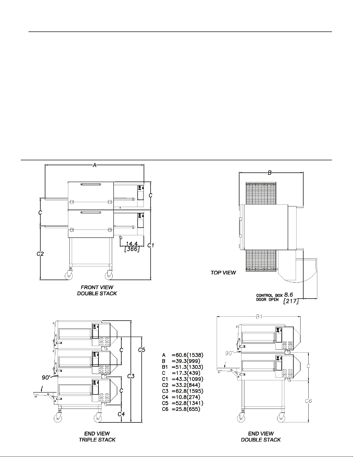
Dimensions: Width: 60.6" (153.9 cm)
Depth: 39.9" (99.82 cm) - Front Door(s) Closed
51.3" (130.3 cm) - Front Door(s) Open
Height: 43.3" (110.0 cm) - Single Oven with Stand
60.6" (153.9 cm) - Double Oven with Stand
62.8" (159.5 cm) - Triple Oven with Dolly
Recommended Minimum Clearances:
Rear of Oven to Wall 0" (0 cm)
3
GENERAL INFORMATION
This equipment is designed and sold for commercial
use only by personnel trained and experienced in its
operation and is not sold for consumer use in and
around the home nor for use directly by the general
public in food service locations.
First and foremost, each crate should be examined
before signing the Bill of Lading to report any visible
damage by the trucker in transit and to account for the
proper number of crates. If there is apparent damage,
arrangements should be made to le a claim against the
carrier
the claim must be initiated by the consignee. Proper
and secure storage facilities should be arranged for
the oven(s) if necessary to protect it from outdoor or
damp conditions at all times before installation.
-IMPORTANT-
When you have all the crates unloaded, open the
crates and remove all plastic covers. Inspect at once
for concealed damage. If anything appears to be
damaged, contact the appropriate persons immediately
to le a damage claim. After completing this inspection,
nish unpacking the oven. Be sure to remove all paper
protection and packing material from the unit prior to
lighting.
CAUTION
. Interstate Commerce Regulations require that
NOTICE
This appliance must be installed with a stand and
casters designed by Star Manufacturing as part of a
complete installation. The installation must also include
a connector complying with either ANSI Z21.69 or CAN/
CGA-6.16 and a quick-disconnect device complying
with either ANSI Z21.41 or CAN1-6.9. It must also
be installed with restraining means to guard against
transmission of strain to the connector as specied in
the appliance manufacturer's instructions.
For your protection, we recommend a qualied
installing agency install this appliance in
accordance with the rules in force within
the country of destination. They should be
familiar with gas installations and your local
gas requirements. In any case, your gas
company should be called to approve the nal
installation.
This appliance, its pressure regulator, and its individual
shutoff valve must be disconnected from the gas supply
piping system during any pressure testing of that system
at test pressures in excess of 1/2 PSIG. This appliance
and its pressure regulator must be isolated from the gas
supply piping system by closing its individual manual
shutoff valve during any pressure testing of the gas
supply piping system at test pressures equal to or less
than 1/2 PSIG.
FOR YOUR SAFETY DO NOT STORE OR USE
GASOLINE OR OTHER FLAMMABLE VAPORS
AND LIQUIDS IN THE VICINITY OF THIS OR
ANY OTHER APPLIANCE.
The installation of the Appliance must conform to
"ANSI Z223.1 - LATEST EDITION" AND ALL LOCAL
GAS COMPANY RULES AND REGULATIONS.
IN CANADA INSTALLATION SHALL BE IN
ACCORDANCE WITH THE CURRENT CAN/CGAB149.1 NATURAL GAS INSTALLATION CODE OR
CAN/CGA-B149.2 PROPANE INSTALLATION CODE
AND LOCAL CODES WHERE APPLICABLE.
PURCHASER'S RESPONSIBILITY
It is the responsibility of the purchaser:
1. To see that the gas and electric services for
the oven are installed on site in accordance
with the manufacturer's specications.
2. To unload, uncrate, and install the oven in its
proper location and in accordance with this
installation operation manual.
3. To see that all gas and electric services are
connected properly by a qualied installer
of your choice. All such connections must
be in accordance with applicable code
requirements.
4. To arrange for inspection and operation checkout by an authorized service technician. The
warranty becomes effective upon verication
of proper installation.
4
IMPORTANT SAFETY INFORMATION
Do not attempt to operate the oven until connection of
utility service has been fully inspected by an authorized
service technician or a Star Service Representative.
This service is required by Star in order to assist the
purchaser in proper start-up of the oven on site. Please
note the specic details on the Warranty and make
certain
utility services.
The warranty shall not apply if the oven is started
up and operated prior to the utilities and oven being
inspected and check-out made by an authorized service
technician or a Star Service Representative.
that service connections are made to proper
CAUTION
IMPROPER INSTALLATION, ADJUSTMENT,
ALTERATION, SERVICE, OR MAINTENANCE
CAN CAUSE PROPERTY DAMAGE, INJURY,
OR DEATH. READ ALL INSTRUCTIONS
THOROUGHLY BEFORE INSTALLING OR
SERVICING THIS EQUIPMENT.
CAUTION
Post in a prominent location the emergency telephone
number of your local gas supplier and instructions to
be followed in the event you smell gas. If the smell
of gas is detected, immediately call the emergency
phone number of your local gas company. They will
have personnel and provisions available to correct
the problem.
CAUTION
It is required that the oven be placed under a
ventilation hood to provide for adequate air supply
and ventilation.
CAUTION
Adequate clearance for air openings to the combustion
control chamber on the right side of the oven is required.
Do not obstruct the ventilation holes in the control panels
as these provide the combustion air for the burner and
cooling air for the controls.
CAUTION
The oven is to be operated only on the type of gas
and electricity shown on the specication plate. The
burner will not operate and gas will not ow through
the burner without electric power.
INSTALLATION INFORMATION
THE INSTALLATION INSTRUCTIONS
CONTAINED HEREIN ARE FOR THE USE OF
QUALIFIED INSTALLATION AND SERVICE
PERSONNEL ONLY. INSTALLATION OR
SERVICE BY OTHER THAN QUALIFIED
PERSONNEL MAY RESULT IN DAMAGE TO THE
OVEN AND/OR INJURY TO THE OPERATOR.
Qualied installation personnel are individuals, a rm,
a corporation, or a company which either in person
or through a representative are engaged in and
responsible for:
1. The installation or replacement of gas piping and
the connection, installation, repair, or servicing of
equipment.
2.
The installation of electrical wiring from the electric
meter, main control box, or service outlet to the
electric appliance.
Qualied installation personnel must be experienced in
such
work, familiar with all precautions required, and
have complied with all requirements of state or local
authorities having jurisdiction.
CAUTION
Minimum clearances must be maintained from all walls
and combustible materials. Minimum clearances for
this unit should be 0 inches from the rear (rear bumpers
provided must be in place) and 6 inches from both
sides. Keep the oven free and clear of all combustible
material.
5
LOCATION
The well-planned and proper placement of your oven
will result in long-term operator convenience and
satisfactory performance.
NOTE:
usually be accomplished within the limited movement
provided by the gas hose restraint. If the oven needs
to be moved further from the wall, the gas must rst
be
removing the restraint. Reconnect the restraint after
the oven has been returned to its regular position.
It is essential that an adequate air supply to the oven
be maintained to provide a sufcient ow of combustion
and
1. Place the oven in an area that is free of drafts.
2. Keep the oven area free and clear of all combustibles
3.
4. On all models, tripping of the blower motor's thermal
On gas conveyor ovens, routine servicing can
turned off and disconnected from the oven before
ventilation air. Follow these guidelines:
such as paper, cardboard, ammable liquids, and
solvents.
Do not place the oven on a curb base or seal to a
wall. This will restrict the ow of air and prevent
p
roper ventilation to the blower motors. This
condition must be corrected to prevent permanent
damage to the oven.
overload device indicates an excessive ambient
temperature at the back of the oven. This condition
must be corrected to avoid permanent damage to
the oven.
CAUTION
VENTILATION
A VENT IS REQUIRED: Local codes prevail. These
are the "authority having jurisdiction" as stated by the
National Fire Protection Association, Inc. in NFPA
96-Latest Edition. For further ventilation information
see below.
A ventilation hood is required to remove heat and
cooking odors. For gas ovens, a ventilation hood is
also required to remove the products of combustion.
The hood and HVAC installation must meet local codes
to gain approval by the authority having jurisdiction.
Requirements may vary throughout the country
depending on the location by city, county, and state.
Obtain information from the authority having jurisdiction
to determine the requirements for your installation.
Obtain information and review copies of codes or
documents that will be used to inspect and approve your
installation. Your ventilation hood supplier and HVAC
contractor should be contacted to provide guidance.
A properly engineered and installed ventilation hood
and HVAC system will expedite approval and reduce
oven maintenance costs. Proper ventilation is the
responsibility of the oven's owner.
The ventilation hood must operate in harmony with the
building HVAC system. It typically requires between
750 and 2500 CFM exhaust. (The efciency of various
hood
designs makes it necessary to specify such a
wide range of ventilator CFM.) Make-up air must be
supplied by either a hood design or the HVAC system
to avoid a negative pressure condition. This will vary
with hoods from various manufacturers.
Failure to properly vent the oven can be
hazardous to the health of the operator
and may result in operational problems,
unsatisfactory baking, and possible damage
to the equipment.
Damage sustained as a direct result of improper
ventilation will not be covered by the warranty.
CAUTION
Prevent airow through the cooking tunnel. Air
must NOT be directed onto the oven's front or
rear or to the sides of the cooking area.
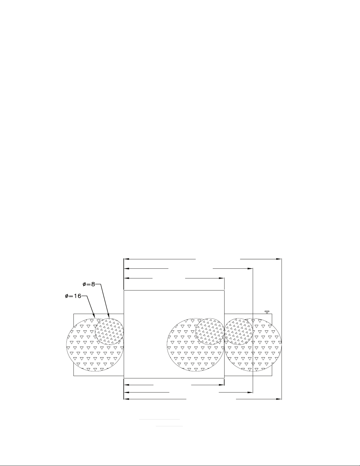
6

The following drawing shows a typical installation
and is intended to be a guideline. This is not a rigid
specication. Hood dimensions and positioning over
the oven will vary with hood manufacturer.
SMOKE CANDLE TEST
In order to verify the proper function of your ventilation
system, a smoke candle test should be done. If testing
a multiple oven system, this test should be done on
the bottom oven. The conveyor coupling should be
disconnected and the oven temperature must be set
and operating at a minimum of 480°F (249°C).
Test Procedure:
1. Wear heat-resistant gloves to prevent burns.
2. Put the smoke candle in an 8"x8"x2" cake pan.
3. Insert candle through conveyor tunnel or oven door.
(Use Star Smoke Candle 2W-Z5668.)
4. Light the fuse of the smoke candle and immediately
center the pan in the oven cavity on the conveyor
belt (keeping the oven door closed).
5. Observe the smoke pattern coming out of all oven
openings and the collection of this smoke by the
ventilation system.
6. All smoke from the oven must be captured by the
ventilation system.
GAS SUPPLY RATING AND SIZING
Calculations for pipe sizing must take into account
the maximum usage rate of all other appliances in the
kitchen or one or more of the appliances will suffer from
inadequate or dangerous performance. The 1/2" BSP
connection for the oven is generously sized for use
in the control box of the oven. However, unless the
oven installation is within 10 feet of the main building
gas supply, the supply must be larger. For each oven,
a 3/4" exible quick connect hose and full port gas
shut-of
main pipe supplying each oven branch may need to be
larger depending on the number of appliances serviced,
the number of elbows in the piping, and the pressure.
This should be sized and installed by a professional
familiar with any local codes that may also affect the
installation.
f valve is recommended as a MINIMUM. The
ACCESS CONSIDERATIONS
Locating the gas valve(s), quick connect hose(s) and
electrical outlet(s) at the control box end of the oven will
allow easier access for any service visits. This improved
access should make any necessary service quicker
resulting in less kitchen disruption. It will also allow
easier disconnection of electricity, gas, and restraints
for cleaning around and behind the oven.
ELECTRICAL CONNECTION
Before making any electrical connections to this unit,
check that the power supply is adequate for the voltage,
amperage, and phase requirements stated on the rating
plate. A wiring diagram is included herewith.
When installed, this appliance must be electrically
grounded and its installation must comply with IEC
codes, manufacturer's installation instructions, and
applicable local municipal building codes.
PRESSURE REGULATION AND TESTING
Each oven is supplied with a regulator to maintain
the proper gas pressure. The regulator is essential
to the proper operation of the oven and should not
be removed. A pressure reading can be taken at the
9mm test port on the rear of the combination valve.
The reading should be taken while the oven is heating
up. The regulator is located on the bottom of the gas
combination valve, just inside the control box. There
is no need to install an additional regulator where the
oven connects to the gas supply unless the supply
exceeds the maximum.
NOTE: The supplied regulator is evaluated for a
maximum gas supply pressure of 14" water column
(34.5 mBar). The recommended maximum gas supply
pressure is 12" water column (29.9 mBar).
7
Installation must conform with local codes or, in the
absence of local codes, with NFPA54/ANSI Z223.1
- Latest Edition.
CAUTION
During pressure testing note the following:
1. The oven and its individual manual shut-off valve
must be disconnected from the gas supply piping
system during any pressure testing of that system
at test pressures in excess of 1/2 psig (3.45 kPa).
Turn OFF main gas shut-off valve or main gas
supply line.
2. The oven must be isolated from the gas supply
piping system by closing its individual manual
shut-off valve during any pressure testing of the
gas supply piping system at test pressures equal
to or less than 1/2 psig (3.45 kPa).
3. If incoming pressure is over 14" water column, a
separate regulator for the oven must be installed
before the gas supply to the oven. It must
regulate pressure to 11" water column (27.1 mBar)
maximum.
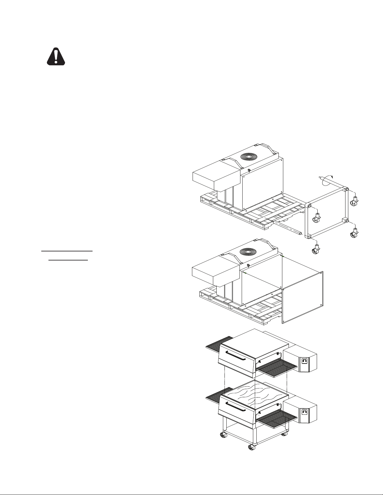
Stacked Oven Install Preparation:
1. Remove door, conveyor, and nger assemblies.
2. Unbolt unit from shipping crate (4 bolts).
3. Turn unit on front as shown.
4. Remove top of lower oven (4 screws total, 2 each
front and rear) and bolt to stacked oven base using
5/8 - 11 bolts (4 each, included).
5. Place top oven on lower unit and re-attach with
screws for top of lower oven.
6. Use restraint on lowest oven to prevent any high
loads that could tip the oven stack.
WARNING: To prevent damage to the control
valve regulator during the initial turn-on of gas,
it is very important to open the manual shut-off
valve very slowly. After the initial gas turn-on,
the manual shut-off valve must remain open
except during pressure testing as outlined in
the above steps or when necessary during
service maintenance.
STACKING INSTRUCTIONS
The following instructions should be followed when
stacking more than one unit.
Single Oven (or Bottom) Cart Install:
1. Remove door, conveyor, and nger assemblies.
2. Unbolt unit from shipping crate (4 bolts).
3. Turn unit on front as shown.
4. Slide legs into stand shelf and thread legs into
bottom of oven.
5. Install casters into bottom of legs. Place casters
with brakes to the front.
6. Position shelf as desired and fasten to legs.
7. CAREFULLY lift oven upright.
8
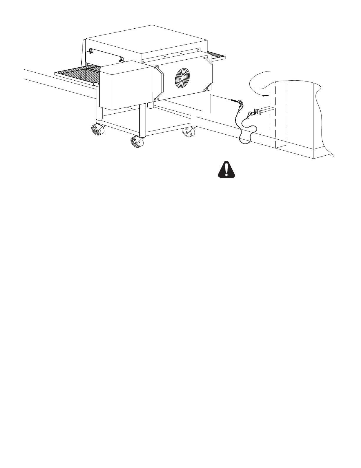
RESTRAINT REQUIREMENT
HOLLOW WALL STUD
OR MASONRY WALL
A
B
C
CAUTION
1. The installation shall be made with a gas connector
that complies with local codes for connectors for
movable gas appliances and a quick-disconnect
device that complies with local codes for such
devices in use with gas fuel.
2. The installation of the restraint must limit the
movement of the oven(s) without depending on
the connector, the quick disconnect device, or
associated piping to limit the oven movement.
3. If the restraint must be disconnected during
maintenance or cleaning, it must be reconnected
after the oven has been returned to its originally
installed position.
OPERATING INSTRUCTIONS
DO NOT ATTEMPT TO OPERATE THE OVEN until
connection of utility service and installation has been
fully inspected (start-up check-out) by an authorized
service technician or your dealer/distributor in order to
assure the oven is properly installed and in working
order. The warranty becomes effective upon
verication of proper installation.
DO NOT WORK AROUND THE CONVEYOR
BELT WITH LONG HAIR, LOOSE CLOTHING, OR
DANGLING JEWELRY. GETTING CAUGHT IN
THE BELT COULD RESULT IN DISMEMBERMENT
OR FATAL INJURY.
Unless specied otherwise, conveyor travel is factory
set for left to right operation when facing the front of
the oven. If a direction change is required, refer to
"DISPLAY INFORMATION," section 3 for instructions
on how to program the controller for a direction change.
In addition, the conveyor belt must be changed to travel
in the new direction.
SAFETY OPERATING INSTRUCTIONS
The information contained in this section is provided
for the use of qualied operating personnel. Qualied
operating
read the information contained in this manual, are
familiar with the functions of the oven and/or have
had previous experience with the operation of the
equipment described. Adherence to the procedures
recommended herein will assure the achievement of
optimum performance and long, trouble-free service.
personnel are those who have carefully
9
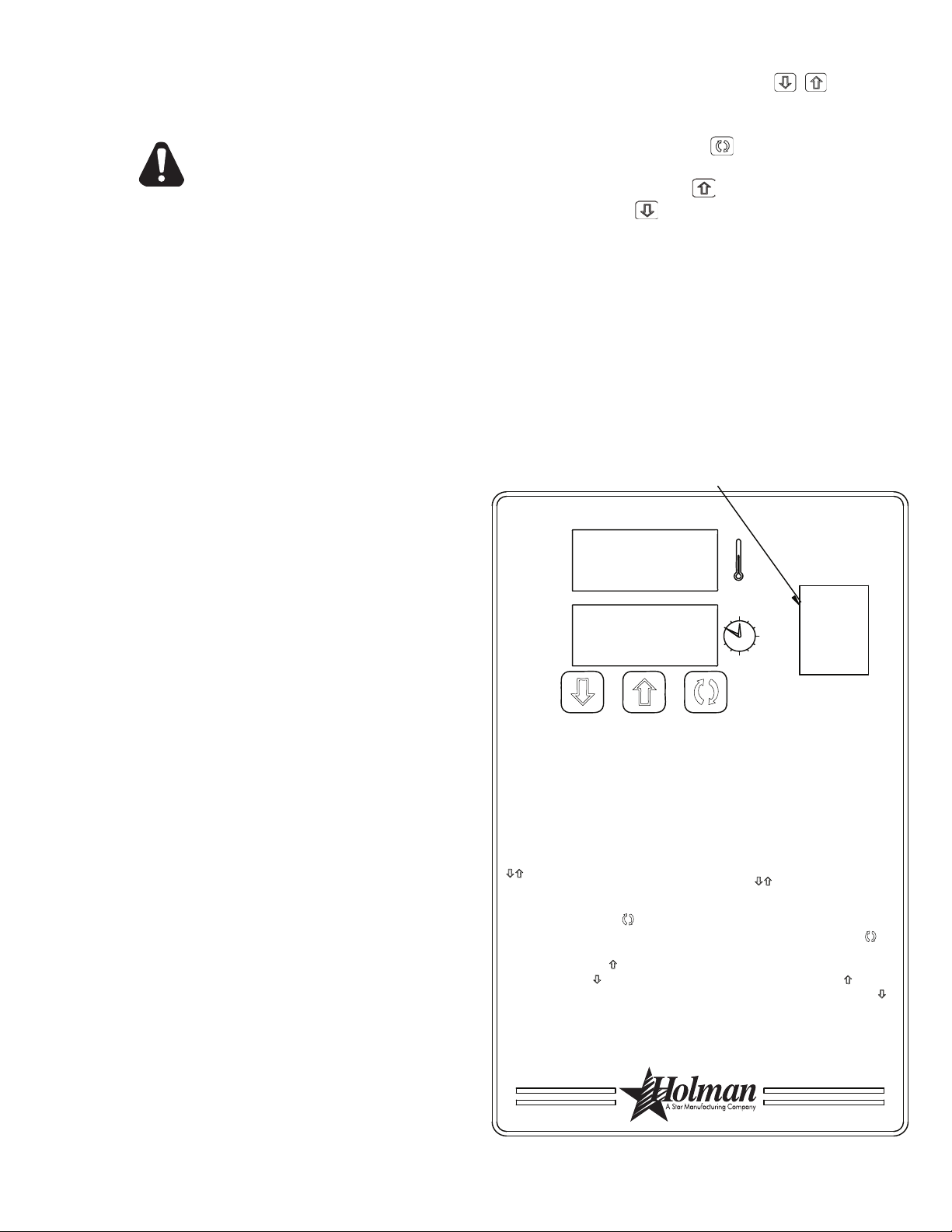
3) Press the up button ( ) to increase
or the down button ( ) to decrease
TIME or TEMPERATURE. Hold
button down for faster display
changes.
4) After five seconds, the new numbers
will be saved and the oven will display
new settings.
4) Après cinq secondes, les nouveaux
nombres seront sauvés et le four montrera
de nouveaux arrangements.
3) Tenez "vers le haut" bouton ( ) pour
augmenter ou "vers le bas" boutonnez ( )
pour diminution de le TEMPS ou
TEMPÉRATURE. Maintenez le bouton pour
des changements plus rapides.
1) Press the up and down buttons
( ) at the same time, hold for four
seconds until TIME display is blank.
2) Press the enter button ( ) to
switch between TIME and
TEMPERATURE.
Adjusting TIME and TEMPERATURE:
If burner does not light in one minute
push the power switch to the "OFF"
position and wait five minutes.
After five minutes, retry.
Push power switch "ON."
To Start:
2) Appuyez sur le bouton de "entrée" ( )
pour commuter entre le TEMPS et la
TEMPÉRATURE.
1) Tenez "vers le haut" et "vers le bas"
boutonne ( ) en même temps. Tenez
les boutons pendant quatre secondes
jusqu'à ce que l'affichage de la
TEMPS soit blanc.
Après cinq minutes, nouvelle tentative.
Si le brûleur n'allume pas en une minute,
poussée le commutateur de puissance dans
la position de "ARRÊTE" et attend 5 minutes.
Poussez le commutateur de puissance à
"MARCHE."
OFF / ARRÊTE
Ajustement du TEMPS et de la
TEMPÉRATURE:
Pour Commencer:
ON / MARCHE
SWITCH CUTOUT
IL1050
Please take time to read the following safety
operating instructions. They are the key to the
successful operation of your Ultra-Max Conveyor
Oven.
SAFETY TIPS
For your safety, read before operating.
If you smell gas:
1. DO NOT try to light any appliance.
2. DO NOT touch any electrical switches.
3. Use an exterior phone to call your gas supplier
immediately.
4. If you cannot reach your gas supplier, call the re
department.
In the event of a power failure:
1. Turn all switches off.
2. DO NOT attempt to operate the oven until the power
is restored.
NOTE: In the event of a shut-down of any kind, allow
a ve (5) minute shut-off period before attempting
to
restart the oven.
General Safety Tips:
To adjust the time and temperature:
1. Press the DOWN and UP arrows ( ) at the
same time. Hold for four seconds until the TIME
display goes blank.
2. Press the ENTER button (
) to switch between
TIME and TEMPERATURE.
3. Press the UP arrow (
DOWN arrow (
) to decrease the TIME or
) to increase or the
TEMPERATURE. Hold either button down for
faster display changes.
4. After ve seconds, the new numbers will be saved
and the oven will display the new settings.
To turn the oven off:
1. Push the power switch to "OFF." The oven is
equipped with a cool-down feature for motor shaft
and bearing protection. This enables the blower
motor(s) to run regardless of the controller status.
The blower(s) continue to run until the oven cools
to a safe temperature.
1. DO NOT use tools to turn off the gas control. If
the gas cannot be turned off manually do not try
to repair it. Call a qualied service technician.
2. If the oven needs to be moved for any reason, the
gas must be turned off and disconnected from the
unit before moving the restraint cable. Reconnect
the restraint after the oven has been returned to
its original location.
3. DO NOT remove the control box cover unless
theoven is unplugged.
OPERATION
To turn the oven on:
1. Push the power switch to "ON."
2. If the burner does not light in one minute, push the
power switch to the "OFF" position and wait ve
minutes.
3. After ve minutes, retry.
10
DISPLAY INFORMATION
When operating the oven, there are three levels
of access:
1. Store Level - General employees would know these
functions and how to change them. While the oven
is running, enter this mode by holding the DOWN
and UP arrows (
seconds. The TIME display goes blank and the
TEMP setpoint is displayed. Adjust with the DOWN
or UP arrows. The ENTER button (
between TIME and TEMP. The parameter that can
be adjusted is displayed, the other is blank. When
TIME and TEMP are adjusted as needed, wait
ve seconds and SAVE is displayed. The values
are accepted and the controller begins controlling
to these new values. The conveyor continues to
operate at the same speed until a new value is
accepted. The temperature control output should
be OFF during changes.
2. Manager Level - This is a lock so that TIME and
TEMP cannot be changed even at the Store Level.
While the oven is running, enter this mode by
holding the DOWN and UP arrows simultaneously
for 4 seconds. The TIME display goes blank and
the TEMP setpoint is displayed. Release the
UP arrow and continue to hold the DOWN arrow
for an additional 4 seconds. The TEMP display
shows LOC as the TIME display shows nO, which
indicates that the TIME/TEMP parameters can be
changed
) simultaneously for four
) toggles
after reaching the STORE level. yES indicates
that the parameters cannot be changed even after
entering the STORE level. The LOC setting can
be toggled using the ENTER button (
).
ADDITIONAL FUNCTIONS
The conveyor belt direction and the temperature
display can be changed on the conveyor oven
by a qualied technician. To change the belt
direction, the technician must reverse the motor
direction and rotate the conveyor belt for proper
oven function. A technician can also change the
temperature display from Fahrenheit to Celsius.
These changes can be made by the technician
during the start-up/check-out or at a later date.
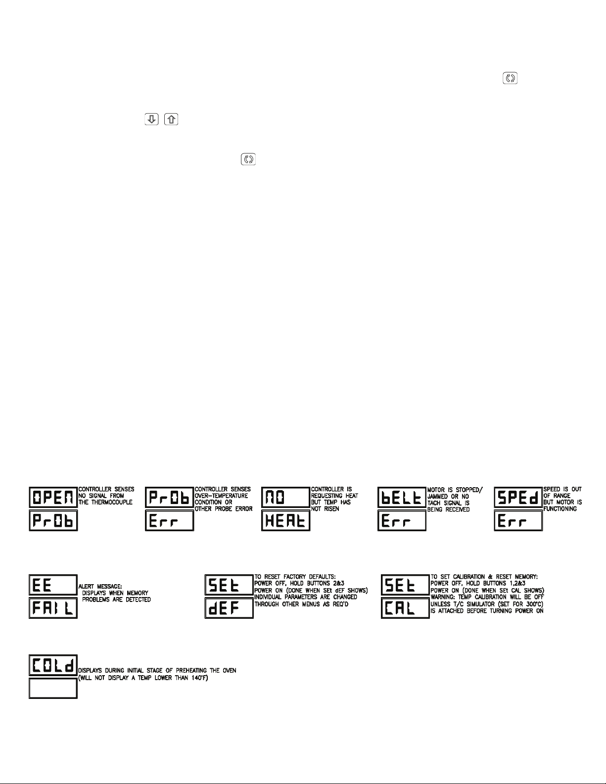
ERROR CODES
Error codes will display as ashing text messages for
diagnostic purposes. Any temperature or thermocouple
error should turn the temperature output OFF and leave
the conveyor running at the same speed. The belt error
should turn the temperature output OFF. The speed
error should display when the motor is unable to settle
at the chosen speed. This might occur if a fast speed
is chosen that the motor is unable to spin fast enough
to achieve. The speed signal output will remain the
same but the display will ash the error message.
11
BAKE TIME VERSUS TEMPERATURE
BAKE vs. DELIVERY TIME
Time to Delivery changes with product
but
Bake Time remains constant
at a steady conveyor speed.
28 (BAKE)
36 (DELIVERY)
44 (DELIVERY)
6:00 (BAKE)
7:43 (DELIVERY)
9:26 (DELIVERY)
1. Bake time is actually conveyor speed and is dened
as the time the product is actually in the oven. This
is measured by noting the time when the leading
edge of the product enters the oven and the time
the leading edge of the product leaves the oven.
This is adjusted by using the conveyor speed
controller.
2. Bake temperature is adjusted by changing the
setpoint of the temperature controller to the desired
bake temperature. When the oven reaches the
desired temperature, the red dot in the lower right
corner of the temperature display will turn off and
on as the controller maintains the temperature.
3. When establishing a bake time and temperature
for a given product, the general rule shall be as
the bake time increases the bake temperature
decreases and the reverse is also true; increase
temperature, decrease time. However, there are
limits to the above rule. Going to extremes will result
in a burnt exterior and raw interior or it will result
in a very light color but over-baked product.
4. Once a good bake has been established, the ne
adjustments should be made by holding either
the bake time or bake temperature constant, then
varying the other.
CONVEYOR SPEED
Bake Time (Conveyor Speed) - As stated previously,
bake time (conveyor speed) is dened as the amount
of time elapsed between the time the leading edge of
the product enters the oven and the leading edge of
the product exits the oven. Bake time is controlled by
adjusting the digital speed controller. The setting on
the control panel indicates the actual bake time.
Bake time will be the same for any size product.
TIME OF DELIVERY
The time of delivery is the amount of elapsed time
between the period when the leading edge of the
product enters the oven and the trailing edge of the
product is fully discharged and is ready to be delivered
to the customer.
Time of delivery changes if the product size
changes.
Tip: Train yourself not to pull the product out of the
oven when the leading edge comes out. Always wait
until the entire product is out - the product needs this
time to fully bake.
12
 Loading...