

Star Manufacturing SSG24 Installation Manual

STAR PROFESSIONAL
OUTDOOR GRILL
SSG Series
SSG48C
Installation and Operating Instructions
2M-Z6972 Rev. C 5/4/2006
1

SAFETY SYMBOL
Using any part other than genuine Star factory supplied parts relieves
the manufacturer of all liability.
Star reserves the right to change specifi cations and product design
without notice. Such revisions do not entitle the buyer to corresponding changes, improvements, additions or replacements for previously
purchased equipment.
Due to periodic changes in designs, methods, procedures, policies and
regulations, the specifi cations contained in this manual are subject to
change without notice. While Star Manufacturing exercises good faith
efforts to provide information that is accurate, we are not responsible for
errors or omissions in information provided or conclusions reached as
a result of using the specifi cations. By using the information provided,
the user assumes all risks in connection with such use.
This symbol is intended to alert the user to the presence
of important operating and maintenance instructions in the
manual accompanying the appliance.
RETAIN THIS MANUAL FOR FUTURE REFERENCE
The installer shall leave this instruction manual with the
grill for use by the end consumer.
NOTICE
MAINTENANCE AND REPAIRS
Contact your local dealer for service or required maintenance. For your convenience, you may contact the Star
Service Help Desk for questions and inquiries by telephone at 1-800-807-9054, by fax at 1-800-396-2677, or
by e-mail at info@star-mfg.com. Please have your model number and serial number for faster service.
PRODUCT INFORMATION
Enter the requested information below for easy reference.
Model Number Serial Number
Purchase Date Purchase Location
Installation Date Installer Name
Installer Phone Installer Address
2

Table of Contents
Safety Statements 5 - 7
General Information ...........................................................................................................................................5
Purchaser's Responsibility ................................................................................................................................5
California Proposition 65 Warning .....................................................................................................................6
Safety Practices to Avoid Injury .........................................................................................................................6
Additional Safety Statements ............................................................................................................................7
Propane Gas Usage 8 - 9
Propane (LP) Gas Warnings .............................................................................................................................8
Important Safety Information .............................................................................................................................8
LP Gas Cylinder Information .............................................................................................................................8
Overfi ll Protection Device (OPD) .......................................................................................................................9
BTU Delivery .....................................................................................................................................................9
LP Regulator Hose Assembly (Type 1) ..............................................................................................................9
Grill Installation 10 - 13
Locating the Grill ..............................................................................................................................................10
Access Considerations ....................................................................................................................................10
Built-In Placement ...........................................................................................................................................10
Electrical Requirements / Connection .............................................................................................................10
Clearance to Non-Combustibles ......................................................................................................................11
Clearance to Combustibles .............................................................................................................................11
Grill Head and Base Installation ......................................................................................................................12
Gas Requirements ...........................................................................................................................................12
Natural Gas Installation ...................................................................................................................................13
LP Gas Installation (Type 1 Regulator) ............................................................................................................13
Leak Testing ....................................................................................................................................................13
To Perform a Leak Test / To Fix a Leak ...........................................................................................................13
Grill Features 14 - 16
The Grill ...........................................................................................................................................................14
Grill Combo ......................................................................................................................................................15
Control Pod ......................................................................................................................................................15
Grill Burners .....................................................................................................................................................16
Grill Operation 17 - 23
Lighting the Grill ...............................................................................................................................................17
Match Lighting: Grill Burner ............................................................................................................................17
Smoker Burner ......................................................................................................................18
Infrared Broiler Burner ...........................................................................................................18
Side Burners ..........................................................................................................................18
Infrared Rotisserie Burner .....................................................................................................19
Burner Adjustments .........................................................................................................................................20
Control Valve Low Setting ...............................................................................................................................20
Using the Electronic Control Pod .....................................................................................................................20
Temperature Display ........................................................................................................................................21
Using the Electronic Timer ...............................................................................................................................21
Grill Surface Light ............................................................................................................................................22
Changing the Grill Light Bulb ...........................................................................................................................22
Locking the Casters .........................................................................................................................................22
End Shelves: Raising/Lowering ......................................................................................................................22
Power Panel ....................................................................................................................................................23
Cooking Features 24 - 26
Grill ..................................................................................................................................................................24
Smoker ............................................................................................................................................................24
Rotisserie .........................................................................................................................................................25
Menu Guide .....................................................................................................................................................26
3

Table of Contents
Care and Maintenance 27 - 29
Cleaning and Care of Your Grill .......................................................................................................................27
Ignitor Battery Replacement ............................................................................................................................29
Clearing Spider Webs and Nests ....................................................................................................................29
Grill Troubleshooting Guide 30
Warranty 31
Wiring Diagrams 32 - 33
Exploded Views and Parts Lists 34 - 51
Grill Body Removable Parts ............................................................................................................................34
Grill Body Service Parts ...................................................................................................................................36
Lower Grill Body Service Parts ........................................................................................................................38
Faceplate & Ignitor Wire Assembly ..................................................................................................................40
Manifold Assembly ...........................................................................................................................................42
Control Pod Assembly .....................................................................................................................................44
Side Burner / Island Assembly .........................................................................................................................46
Side Shelf Burner & Accessories Assembly ....................................................................................................48
Grill Bases Assembly .......................................................................................................................................50
Burner, Orifi ce, and Ignitor Table 52
Notes 53 - 55
4

Safety Statements
GENERAL
Read this installation operation manual thoroughly before attempting to operate
INFORMATION
IMPORTANT After unloading the crate containing your Star Grill, remove any plastic or
Before using your Star Grill, be sure to unpack all components such as the
It is the responsibility of the purchaser:
PURCHASER'S
RESPONSIBILITY
2. To see that gas and electric services for the grill are installed in accordance with
your Star Grill. Proper installation and servicing will ensure the long life of your grill.
Adherence to the safety statements in this manual will allow for safe and effective
operation.
paper packing materials along with any tie-downs used to hold burners or
other items in place. It is essential that all plastic or paper protection and
packing materials be removed from the unit prior to lighting.
skewer, meat prongs, mitts, electronic control pod, and grates. Be sure to
locate all radiant panels and grates on the unit before using.
1. To read this installation manual completely before attempting to install, service,
or operate the Star Grill and to retain these instructions for future reference.
all applicable codes by a qualifi ed installer of your choice.
3. To place the grill in a safe location as specifi ed by this installation manual and
all applicable codes.
IMPORTANT Do not attempt to operate the grill until connection of utility service has
been fully inspected by an individual familiar with all local gas codes and
regulations.
CAUTION IMPROPER INSTALLATION, ADJUSTMENT, ALTERATION, SERVICE, OR
MAINTENANCE CAN CAUSE PROPERTY DAMAGE, INJURY, OR DEATH. READ
ALL INSTRUCTIONS THOROUGHLY BEFORE INSTALLING OR SERVICING
THIS EQUIPMENT.
FOR YOUR SAFETY
If you smell gas:
1. Shut off gas to the appliance.
2. Extinguish any open fl ame.
3. Open hood.
4. If odor continues, immediately call your supplier
or your fi re department.
1. Do not store or use gasoline or other fl ammable
vapors and liquids in the vicinity of this or any other
appliance.
2. An LP cylinder not connected for use shall not be
stored in the vicinity of this or any other appliance.
TESTED IN ACCORDANCE WITH ANSI Z21.58b STANDARD FOR OUTDOOR COOKING GAS
APPLIANCES. THIS GRILL IS FOR OUTDOOR USE ONLY.
FOR YOUR SAFETY
Check your local building codes for the proper method of installation. In the absence of local codes,
this unit should be installed in accordance with the National Fuel Gas Code No. Z223.1/NFPA 54 or
CAN/CGA-B149.1, Natural Gas and Propane Installation Code and the National Electrical Code ANSI/
NFPA No. 70 or the Canadian Electrical Code, CSA C22.1.
WARNING DO NOT TRY LIGHTING THIS APPLIANCE WITHOUT READING
THE "LIGHTING INSTRUCTIONS" SECTION OF THIS MANUAL.
5

Safety Statements
CAUTION Post in a prominent location the emergency telephone number of your local gas
supplier and instructions to be followed in the event you smell gas. If the smell
of gas is detected, immediately call the emergency phone number of your local
gas company. They will have personnel and provisions available to correct the
problem.
CAUTION THIS GRILL IS FOR OUTDOOR USE ONLY. DO NOT USE IN BUILDINGS,
GARAGES, SHEDS, OR OTHER TYPES OF ENCLOSED AREAS. DO
NOT USE ON A RECREATIONAL VEHICLE OR BOAT.
WARNING If not installed, operated, and maintained in accordance with the manu-facturer's
instructions, this product could expose you to substances in fuel or from fuel
combustion which can cause death or serious illness.
The burning of gas cooking fuel generates some by-products which are on the
CALIFORNIA
PROPOSITION 65
WARNING
When properly cared for, your grill will give safe, reliable service for many years.
SAFETY
PRACTICES TO
AVOID INJURY
list of substances which are known by the State of California to cause cancer or
reproductive harm. California law requires businesses to warn customers of potential
exposure to such substances. To minimize exposure to these substances, always
operate this unit according to the installation and operating instructions, ensuring
you provide good ventilation when cooking with gas.
However, extreme care must be used since the grill produces intense heat and can
increase accident potential. When using this appliance, basic safety practices must
be followed.
Read this instruction manual carefully and completely before using your grill to reduce
the risk of fi re, burn hazard, or other injury. Begin by ensuring proper installation
and servicing. Do not repair or replace any part of the grill unless specifi cally
recommended in this manual. All other service should be referred to a qualifi ed
technician.
Always be sure to turn off all burners and the gas supply after using the grill. Do
not leave the grill unattended while grilling and do not allow children to play around
the grill or crawl inside the base.
For personal safety, wear proper apparel when grilling. Loose-fi tting garments or
sleeves should never be worn while using this appliance. Some synthetic fabrics
are highly fl ammable and should not be worn while cooking. Only certain types of
glass, heat-proof glass ceramic, earthenware, or other glazed utensils are suitable
for grill use. Using other types of materials may lead to breakage with sudden
temperature changes. Use only on low or medium heat settings according to the
manufacturer's directions.
CAUTION When lighting a burner, always pay close attention to the burner and electric
starter you are using. Do not turn on a burner and leave it on before pushing
the ignitor button since an excess of gas can build up in the grill.
6

Safety Statements
ADDITIONAL
SAFETY
STATEMENTS
When heating or cooking, use a covered or protected hand when opening the grill
hood. Open the hood slowly to allow the heat to escape. Never lean over an open
grill or touch the grill rack, burner grate, hot skewer, or any surrounding areas near
the grill since they can be very hot and could cause serious burns. Always use the
grill mitts provided for handling the roasting spit or roasting pans. Keep the mitts
dry to avoid steam burns.
CAUTION GREASE IS FLAMMABLE. LET HOT GREASE COOL BEFORE
ATTEMPTING TO HANDLE IT.
Avoid grease deposit collection in the drip trays. The drip trays, grates, and grease
trough should be cleaned often with a wire brush. Excessive grease build-up can
lead to a grease fi re. Always have the drip trays in place during operation.
Do not use aluminum foil to line the drip trays or grill racks. This can severely upset
combustion airfl ow or trap excessive heat in the control area. The result of this can
be melted knobs or damaged controls.
Always keep the grill clean. This includes all burners, radiants, grates, drip trays,
and the grease trough. The burners can be easily removed by removing the grate,
the radiant panel, the burner hold down bracket, and then the burner. Be sure all
the burner parts are open and free of any food particles or residue. Do not clean
the grill while it is hot to avoid burns.
CAUTION Some spiders and insects can nest in the burners and orifi ce fi ttings. Some
will make small webs across orifi ces, thereby affecting the proper fl ow of gas
to the burner or causing the gas to burn back into the control compartment.
This can be a dangerous condition which could damage the grill controls or
make it unsafe to operate. Be sure to periodically inspect burners and orifi ces
for this condition.
This grill is designed for use with the gas specifi ed on the nameplate on the underside
of the front panel. Do not use charcoal or charcoal lighter with this grill.
If this grill is kept indoors for storage, detach and leave the LP cylinder outdoors.
Do not operate this grill under unprotected combustible construction. Use only in
well-ventilated areas, but do not use in a windy location. Do not operate the grill
directly under overhanging tree branches.
The grill requires a 120 VAC grounded supply for powering the electronic temperature
readout or the rotisserie motor. Be sure to safely route any power cord to the
base or provide easy access to the power cord connection for built-in models.
Do not operate the unit in the rain or snow with an exposed extension cord.
Keep all ventilation openings to the base and unit bottom free for proper ventilation
and maintain all clearance spacings. Maintain minimum clearance from the sides
and back of the grill to adjacent combustible construction 8 inches from the sides
and 12 inches from the back.
7

Propane Gas Usage
PROPANE
1. Know the odor of LP gas. If you hear, see, or smell leaking LP gas, immediately
(LP) GAS
WARNINGS
2. LP gas is heavier than air and may settle in low places while dissipating.
3. Contact with the liquid contents of a cylinder will cause freeze burns to the skin.
4. Do not allow children to tamper or play with a cylinder.
5. When not connected for use, keep the cylinder valve turned off.
6. Do not use, store, or transport a cylinder where it could be exposed to high
7. When transporting, keep the cylinder secured in an upright position with the
8. CAUTION: The type 1 pressure regulator and connector provided with this outdoor
9. The cylinder supply system must be arranged for vapor withdrawal and include
get everyone away from the cylinder and call the fi re department. Do not attempt
any repairs.
temperatures. The relief valve may open allowing a large amount of fl ammable
gas to escape.
cylinder valve turned off.
cooking gas appliance must be used. The regulator is set for an outlet pressure
of 11 inches water column.
a collar to protect the cylinder valve.
10. The gas supply must be turned off at the LP gas supply cylinder when the grill is
not in use.
IMPORTANT
Certain liquid propane dealers may fi ll liquid propane cylinders for grill use beyond
SAFETY
cylinder fi lling capacity. "Overfi lling" may create a dangerous condition.
INFORMATION
"Overfi lled" tanks can build up excess pressure. As a safety device, the tank's pressure
relief valve will vent propane gas vapor to relieve this excess pressure. This vapor
is combustible and therefore can be ignited.
To reduce this danger, you should take the following safety precautions:
1. When you have your tank fi lled, be sure you tell the supplier to fi ll it to no more
than 80% of its total capacity.
2. If you own or use an extra spare tank or have a disconnected tank, you should
NEVER store it near or under the grill unit or heat box or near any other ignition
or heat source.
3. Failure to follow these instructions may cause fi re, serious injury, or death.
The LP gas supply cylinder to be used must be constructed and marked in accordance
LP GAS
CYLINDER
INFORMATION
with the specifi cations for LP gas cylinders of the U.S. Department of Transportation
(DOT) or the National Standard of Canada, CAN/CSA-B339, Cylinders, Spheres and
Tubes for the Transportation of Dangerous Goods.
WARNING Inspect the fuel supply hose before each use of the grill. The hose can be
accessed by opening the front door on the grill base. If it is evident there is
excessive abrasion, wear, or the hose is cut, it must be replaced prior to the
grill being put into operation. Contact your dealer to obtain a replacement fuel
supply hose. Keep the ventilation openings of the cylinder enclosure free and
clear from debris.
If the grill is not in use, the gas must be turned off at the supply cylinder.
8

Propane Gas Usage
WARNING Do not store a second 20 pound propane cylinder within the Star Grill base. The
base is designed for the use and storage of one 20 pound propane cylinder.
Storage of an outdoor cooking gas appliance indoors is permissible only if the cylinder
is disconnected and removed from the grill. Cylinders must be stored outdoors, out
of reach of children, and must not be stored in a building, garage, or any enclosed
area.
The Overfi ll Protection Device (OPD) will help reduce the potential for the overfi lling
OVERFILL
PROTECTION
DEVICE (OPD)
of the propane cylinder, thus reducing the possibility of hydrostatic relief valve
discharges. This gas grill must be connected to an LP gas cylinder incorporating
an overfi ll protection device.
BTU DELIVERY The OPD valve has a size 56 orifi ce through which the propane is released for
consumption. Depending on the propane's temperature and pressure, the release
from the cylinder is approximately 125,000 Btu/hour.
The pressure regulator and hose assembly supplied with the grill must be used.
A replacement pressure regulator and hose assembly for the grill can be obtained
LP REGULATOR
HOSE ASSEMBLY
(TYPE 1)
by contacting your dealer. This device includes a user-friendly swivel nut, thermal
element, and listed excess fl ow valve. This connection incorporates a thermal
sensing device that will shut off the fl ow of gas when it is exposed to temperatures
in the range of 240°F to 300°F.
The excess fl ow valve is designed to limit the fl ow of LP gas from the container in
the event the connection fi tting, regulator, or hose is broken between the container
valve and the appliance. This device does not stop the fl ow of gas but will limit
the rate of gas fl ow to 10 scfh or less. This device is designed to shut off when it
senses the gas fl ow is in excess of 100,000 Btu/hr for black nuts and 200,000 Btu/hr
for green nuts. This sensitivity will cause the device to activate when the cylinder
valve is opened but will automatically reset within a few seconds as long as there
is no gas leak and all valves have been turned off.
The following steps should be taken each time the cylinder is turned on or it is
determined that the excess fl ow device has been activated (trouble lighting burners,
low fl ame, or low heat):
1. Be sure all valves are turned off, including pilot lights if equipped, prior to turning
the cylinder valve to the on position.
2. Turn the cylinder valve on slowly to reduce gas surging (slamming the excess
fl ow device shut); this will reduce the automatic reset time.
3. Leak test all connections with a bubble solution or non-ammonia soapy water
solution. If a leak is present, the solution will "bubble" at the leak point that
indicates a repair is needed.
4. Allow a minimum of 10 seconds for the excess fl ow device to automatically reset
prior to operating any of the grill burners.
5. If the grill continues to operate improperly, check that the cylinder has gas or
contact a qualifi ed service technician.
9

Grill Installation
Your new Star Grill can be located in a Star Grill base (model series 24SSB, 30SSB,
LOCATING
THE GRILL
The gas valve and electrical outlet should be placed in a convenient location to
ACCESS
CONSIDERATIONS
BUILT-IN
The Star Grill is designed for easy placement into an immovable masonry enclosure.
PLACEMENT
36SSB, or 48SSB) or can be installed into an immovable masonry enclosure. When
selecting a suitable location for your grill, take into account concerns such as wind
exposure and areas of high traffi c. Do not locate the grill close to a home or any
kind of combustible construction. Do not locate overhead shading umbrellas or other
combustible items near or above the grill. Grill exhaust can be very hot and under
extreme conditions can emit fl ames. Maintain an open area around the grill and
enclosure at all times, keeping the area free from combustible materials, gasoline,
and other fl ammable vapors and liquids. Be sure your grill is located on a level
surface. Keep any electrical supply cord and the fuel supply hose away from all
heated surfaces.
allow easy access for any service visits. This access should make any necessary
service quicker and less disruptive and allow easier disconnection of electricity and
gas for cleaning around and behind the grill.
Non-combustible masonry materials are recommended for such installations and
the proper dimensions should be used to provide proper support for the grill. All
clearance locations and ventilation requirements apply whether the grill is used with
a Star Grill base or placed into an immovable masonry enclosure. The following
guidelines must be kept in mind:
1. Do not build your immovable masonry enclosure under unprotected construction
such as awnings or gutters.
2. Do not build under trees, bushes, or shrubs.
3. Your masonry enclosure must take into account all necessary clearances for
gas and electrical lines.
4. Provide ventilation openings in your enclosure to allow for ventilation and detection
of gas leaks. (Recommendation: 25in
bottom on the gas connection side.) Do not obstruct the fl ow of combustion or
ventilation air.
ELECTRICAL
The Star Grill base can have a built-in electrical box with a GFCI receptacle. Deluxe
REQUIREMENTS
For built-in models, hard wiring to a junction box must be performed by a qualifi ed
Before making any electrical connections to this unit, check that the power supply
ELECTRICAL
CONNECTION
models come with this option. A power supply cord can be attached at the box
connector, thereby providing power to the grill head and base. The unit operates
on 120 VAC supply and will normally draw less than 1 amp of current.
installer per the National Electrical Code. Maintain the junction box within a distance
of 3 feet from the grill where the power cord exits. The 3-prong cord measures
approximately 40 inches in length. An easily accessible ON/OFF gas valve should
also be provided in this lower enclosure.
is adequate for the voltage, amperage, and phase requirements stated on the
specifi cation plate.
2
or more free area near the enclosure
10

Grill Installation
25 1/8 [63.8cm]
N US
WHE
26 1/8 [66.3cm]
36 [91.4cm]
20 [50.8cm]
NOTE: 15" MINIMUM SPACING FOR
HOTPLATE-SIDE BURNER ON RIGHT
SIDE OF GRILL
HOTPLATE SPACING TO BE 4" MINIMUM
ON LEFT SIDE OF GRILL.
CLEARANCE
TO NONCOMBUSTIBLES
5 [12.7cm]
ING INSULATED SPACER JACKET
5 [12.7cm]
A
GRILL
HOTPLATE-SIDE BURNER
12 1/2 [31.7cm]
Enclosure
Model "A" Dimension
7
7
7
7
/8"
/8"
/8"
/8"
SSG24 22
SSG30 28
SSG36/36C 34
SSG48/48C 46
Combustible
Enclosure Using
Non-Combustible
Insulated Jacket
Model "A" Dimension
SSG24 28
SSG30 34
SSG36/36C 40
SSG48/48C 52
7
/8"
7
/8"
7
/8"
7
/8"
15 [38.1cm]
MIN. SPACING
A
12 5/8 [32.1cm]
3 [7.6cm]
9 [22.9cm]
10 [25.4cm] WHEN USING
INSULATED JACKET
Maintain a 3" space from the back of the grill for service access and cleaning. The
grill exhausts to the top back of the unit, which may result in occasional grease
build-up. Always consider cleaning and service accessibility when locating the
grill. The right side of the unit must have at least 8" of space above the grill for the
electronic temperature sensing pod. The left side may have zero clearance as may
the lower mounting enclosure.
A minimum of 12" from the back of the unit to combustible construction and 8" from
CLEARANCE TO
COMBUSTIBLES
the sides of the unit to combustible construction must be provided.
The grill may be placed in a combustible enclosure only when used with an insulating
jacket around the grill. The jacket must be supported on its bottom. See cut-out
dimensions for the correct dimensions using the insulated jacket. Use only the Star
Manufacturing supplied jacket for this installation.
12" TO COMBUSTIBLE
CONSTRUCTION
3“ TO
NON-COMBUSTIBLE
CONSTRUCTION
8" TO COMBUSTIBLE
CONSTRUCTION
8
THE GRILL CAN BE PLACED DIRECTLY ADJACENT TO NON-COMBUSTIBLE CONSTRUCTION BELOW THE COOKING SURFACE.
11
Grill Installation
CAUTION DO NOT INSTALL THIS UNIT INTO A COMBUSTIBLE ENCLOSURE
WITHOUT AN INSULATED JACKET. THIS COULD RESULT IN A FIRE,
PROPERTY DAMAGE, OR PERSONAL INJURY.
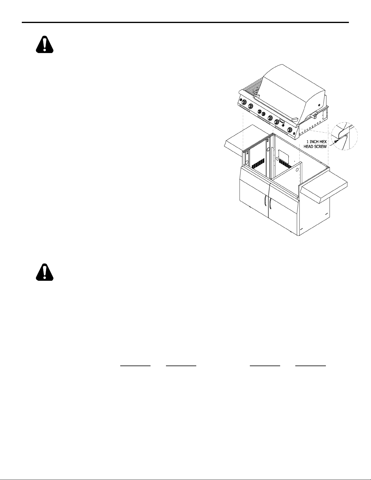
GRILL HEAD
1. Remove the base from the pallet
AND BASE
INSTALLATION
2. Place the base near the grill head and
3. Remove all loose items from the
4. Lift the grill head and place it into the
by removing the screws holding the
packing brackets.
lock the casters.
grill.
base making sure to lower and slide
it back evenly on both sides to keep
it from binding. (NOTE: Make sure
to place the cordset and/or gas hose
into the base in an area where it will
not be sitting on top of a wall or getting
pinched by the grill.)
5. Remove the two upper control panel
screws and replace them with the two
1-inch hex head screws supplied with
the base. (NOTE: The head must be
secured to the base with these screws
before operation.)
CAUTION THE GRILL MUST BE PLACED ON A LEVEL SURFACE AND THE CASTERS MUST
BE LOCKED WHILE OPERATING THE GRILL TO PREVENT MOVEMENT.
Verify that the unit nameplate marking on the upper front panel matches the type of
gas you are using. An installer-supplied gas shut-off valve must be installed in an
easily accessible location. All installer-supplied parts must conform to all local codes
GAS
REQUIREMENTS
Total Btu requirements for the grill with all burners on HI are:
Model Btu Model Btu
SSG24 62,000 SSG30 72,000
SSG36 88,000 SSG36C 102,000
SSG48 119,000 SSG48C 128,000
The appliance, shut-off valve, and regulator must be disconnected from the gas
or, in the absence of local codes, with the National Electrical Code ANSI/NFPA 70
and the National Fuel Gas Code No. Z223.1/NFPA 54. All pipe sealants must be
an approved type and resistant to the actions of LP gas. Do not use pipe sealant
on fl are fi ttings.
supply system during any pressure testing in excess of 1/2 PSIG. The appliance
must be isolated from the gas supply piping system by closing its individual manual
shut-off valve during any pressure testing of the gas supply piping system at test
pressures equal to or less than 1/2 PSIG (3.5 kPa).
12

Grill Installation
NATURAL GAS
INSTALLATION
Grills set for LP gas will come with a 1/2" male x 3/8" fl are connector and a type 1
LP GAS
INSTALLATION
TYPE 1 REGULATOR)
(
The grill has a 1/2 NPT female connector at the rear left side of the grill bottom. Use
the 5" water column natural gas regulator supplied and a short nipple to connect to
the manifold inlet pipe. A natural gas supply line can then be attached to the inlet
side of the regulator. Supply pressure must be between 5" and 14" water column.
Be sure the installation is made by a qualifi ed service technician knowledgable in
all local codes and the National Fuel Gas Code ANSI Z223.1/NFPA 54.
hose/regulator assembly for connection to a standard 20 pound type 1 LP cylinder.
The tank is not included but may be available from your dealer.
The hose/regulator assembly is set for 11" water column. Be sure the tank valve is
closed and then attach the regulator and connector to the tank valve fi tting. Turn
the green coupler clockwise until tight, but be careful to not overtighten the coupler.
Be sure all control knobs are turned OFF and read the lighting instructions carefully
before using the grill. Open the hood. If you do not plan to use the grill, disconnect
the regulator coupling from the tank by slowly turning it counterclockwise.
LEAK TESTING The manifold and all gas connections are factory tested, but a complete leak check
should be performed at the fi nal installation due to possible rough handling during
shipping or some other unknown occurrence. Never operate your grill if the smell
of gas is present.
CAUTION DO NOT USE AN OPEN FLAME OR OTHER IGNITION SOURCE WHILE
PERFORMING A LEAK TEST. DO NOT SMOKE WHILE PERFORMING THIS
TEST. AN EXPLOSION OR FIRE MAY OCCUR.
1. Be sure all power to the unit is turned OFF.
TO PERFORM
2. Make a soapy solution of equal parts mild dishwashing detergent and water.
A LEAK TEST
3. Slowly turn on the gas fuel supply by turning the knob counterclockwise or the
natural gas supply valve on.
4. Using a small brush or squirt bottle, generously apply the water/soap solution
to all connections and fi ttings.
5. If growing bubbles appear on any of the connections, you have a gas
leak. Immediately close the gas supply control valve by turning the handle
clockwise.
TO FIX A LEAK
1. Slowly turn on the gas fuel supply by turning the knob counterclockwise or the
natural gas supply valve on.
2. Turn the control knob to the LITE position for several seconds to release any
gas pressure in the system.
3. Wash/clean off all remaining soap solution and tighten any leaking joints. Faulty
parts will need to be replaced. Use only factory-supplied or recommended parts.
If the cylinder valve is leaking, do not attempt to repair it but instead replace the
entire cylinder.
13

Grill Features
THE GRILL Each grill section consists of an oversized stainless steel burner, a high-performance
radiant panel, and a multi-functional stainless steel grate. Models SSG30 and
larger provide a high-performance infrared broiler burner for the searing of low-fat
meats such as lean cuts of steaks and chops. This broiler burner will provide high
temperature radiant heat to the grates, searing faster than the standard burner.
Your new grill features a back infrared rotisserie burner that can be used to cook
meats on the skewer and meat prongs provided. It also features a built-in rotisserie
drive with a front-mounted power switch. All grills come with a smoker box and
separate smoker burner for smoking your select meats.
The grill features an electronic temperature sensing control pod with the following
features:
1. Bright digital temperature display of grill during operation.
2. Temperature display of meats being cooked using the meat probe.
3. Grill light for cooking at night.
4. Timer control for both count-down and count-up use.
5
12
2
1
4
3
6
11
1. Control Pod
2. Halogen Light
3. Control Pod Mounting Knob
4. Warming Rack
5. Rotisserie Skewer Rod
6. Rotisserie Power Switch
10
14
9
8
7. Grill Burner Ignitor Button
8. Smoker Box
9. Grill Drip Trays
10. Control Knobs
11. Radiant Burner Ignitor Button
12. Grates
7

GRILL COMBO
Grill Features
1
2
1. Side Burners
2. Side Burner Ignitor Button
3. Rear Side Burner Control Knob
4. Front Side Burner Control Knob
CONTROL POD
1
7
3
3
5
2
4
4
6
6
5. Side Burner Drip Tray
6. Grill Drip Trays
7. Smoker Box
8. Grill Burner Ignitor Button
1. Halogen Light
2. Light Power Switch
3. Time Display
4. Temperature Display
5. Meat Probe
6. Temperature Toggles
7. Timer Start/Stop
7
8
15
5

GRILL BURNERS
Grill Features
1
2
1. Infrared Rotisserie Burner
2. Infrared Broiler Burner
3. Grill Burner
3
4. Smoker Box
5. Grates
4
5
16

Grill Operation
CAUTION DO NOT TURN ON ALL THE GRILL/SEARING BURNERS AND LEAVE THE
HOOD CLOSED FOR MORE THAN 20 MINUTES. EXCESS HEAT CAN BUILD
UP INSIDE THE GRILL. OPENING THE HOOD WITH AN UNPROTECTED HAND
OR ARM CAN LEAD TO BURNS CAUSED BY THE RELEASE OF THIS HEAT.
Before attempting to light your grill, check the following:
LIGHTING
1. Turn OFF the tank supply gas to the unit. Do not use the grill if you smell
THE GRILL
2. Be sure the drip trays are in place.
3. Open the hood.
4. Be sure the LP tank connections to the manifold and tank are tight. Inspect
5. Make sure all control knobs are turned to the OFF position.
6. Check that all grates and radiant panels are in place.
7. Do not lean over the grill or place your hands down inside the grill while attempting
gas.
the hose for wear or abrasions. A damaged hose/regulator assembly must be
replaced. If using LP gas, make sure there is fuel in the LP cylinder.
to light it.
CAUTION BEFORE LIGHTING, BE SURE TO LOOK AT THE FRONT PANEL AND NOTE
THE APPROPRIATE IGNITOR BUTTON FOR THE BURNER YOU INTEND TO
LIGHT.
To light, turn ON the tank supply gas. Turn the control knob counterclockwise to
the HI/LITE position and push the correct ignitor button. You should hear a series
of sparks and the burner should light within 5 seconds. You should be able to see
a spark at the ignitor collector box just above the burner. If the burner fails to light,
turn the knob OFF and wait 5 minutes for gas to dissipate before attempting to light
again. If the burner fails to light after several attempts, it can be lit with a match.
MATCH LIGHTING
Grill Burner:
THE GRILL
Make sure all knobs are in the OFF position. Move the grate just above the burner
you intend to light. Turn the control knob for that burner to the HI/LITE position and,
with a lit match, place the fl ame at the small hole of the long notch in the radiant
panel. The burner should light within several seconds. All burners may be lit with
a paperbook match, but for ease of lighting a long-stemmed match or butane lighter
(as shown) is recommended. Locate the lit match/lighter as shown.
17
 Loading...