

Star Manufacturing SC18 Installation Manual

STRIP HEATERS
IL2532
MODEL
SC18, SC24, SC30, SC36,
SC42, SC48, SC60, SC72
Installation and
Operation
Instructions
2M-Z16424 Rev. - 10/31/2012
1
SC36P

2
These symbols are intended to alert the user to the presence of
important operating and maintenance instructions in the manual
accompanying the appliance.
RETAIN THIS MANUAL FOR FUTURE REFERENCE
NOTICE
Using any part other than genuine Star factory supplied parts relieves the
manufacturer of all liability.
Star reserves the right to change specications and product design without
notice. Such revisions do not entitle the buyer to corresponding changes,
improvements, additions or replacements for previously purchased
equipment.
Due to periodic changes in designs, methods, procedures, policies and
regulations, the specications contained in this sheet are subject to change
without notice. While Star International Holdings Inc., Company exercises
good faith efforts to provide information that is accurate, we are not
responsible for errors or omissions in information provided or conclusions
reached as a result of using the specications. By using the information
provided, the user assumes all risks in connection with such use.
MAINTENANCE AND REPAIRS
Contact your local authorized service agent for service or required maintenance.
Please record the model number, serial number, voltage and purchase date in the area below and have it ready when
you call to ensure a faster service.
SAFETY SYMBOL
Model No.
Serial No.
Voltage
Purchase Date
Business 8:00 am to 4:30 p.m. Central Standard Time
Hours:
Telephone: (314) 678-6303
Fax: (314) 781-2714
E-mail Parts@star-mfg.com
Service@star-mfg.com
Warranty@star-mfg.com
Website: www.star-mfg.com
Service Help Desk
Authorized Service Agent Listing
Reference the listing provided with the unit
or
for an updated listing go to:
Website: www.star-mfg.com
E-mail Service@star-mfg.com
Mailing Address: Star International Holdings Inc., Company
10 Sunnen Drive
St. Louis, MO 63143
U.S.A
2
SC24MLIP
None: Low Watt
M: Medium Watt
H: High Watt
I: Infinite
no / I: Toggle
L: Lights
A: Attached Control Box
R: Remote Control Box
P: Plug
no / P: Conduit
SC: Model Designation
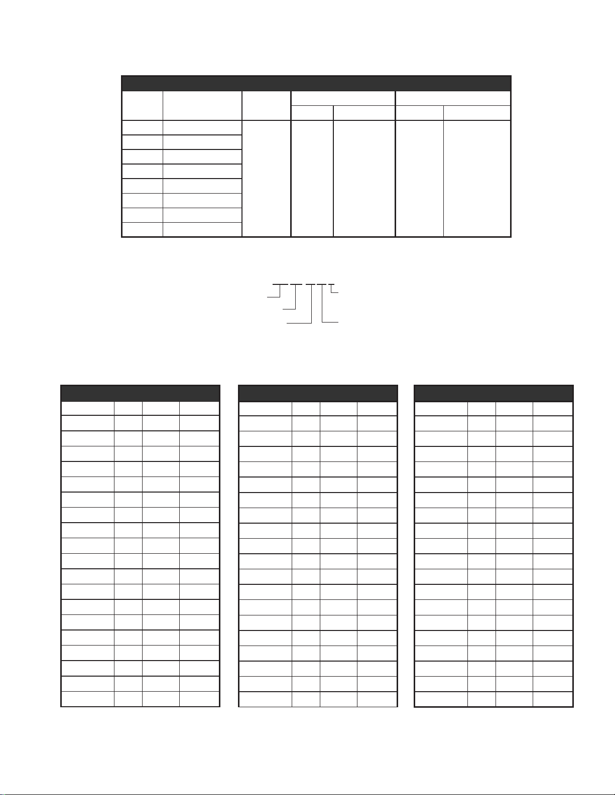
Length
Model Length Height
SC18 18” (45.7 cm)
SC24 24” (61.0 cm)
SC30 30” (76.2 cm)
SC36 36” (91.4 cm)
SC42 42” (106.7 cm)
SC48 48” (121.9 cm)
SC60 60” (152.4 cm)
SC72 72” (182.9 cm)
2.5”
(5.1 cm)
Dimensions
Single Model Dual Model
Width Width w Lights Width Width w Lights
6”
(15.25 cm)
9”
(22.9 cm)
15”
(38.1 cm)
(45.7 cm)
18”
Electrical Specications
MODEL NO. VOLTS WATTS AMPS.
SC18HP 120 375 3.1
SC18H 120 375 3.1
SC24P 120 375 3.1
SC24 120 375 3.1
SC24HP 120 525 4.4
SC24H 120 525 4.4
SC24HI 120 525 4.4
SC24HL 120 645 5.4
2M-Z16424; Strip-Heater
SC24DH 120 1050 8.8
SC24DHL 120 1170 9.8
SC24MIP 120 675 5.6
SC24MR 120 675 5.6
SC24H 208 525 2.5
SC24MR 208 675 3.2
SC30 120 475 4.0
SC30HP 120 685 5.7
SC30H 120 685 5.7
SC36P 120 600 5.0
SC36 120 600 5.0
Electrical Specications
MODEL NO. VOLTS WATTS AMPS.
SC36HP 120 825 6.9
SC36H 120 825 6.9
SC36HI 120 825 6.9
SC36HL 120 1005 8.4
SC36DH 120 1650 13.8
SC36DHL 120 1830 15.3
SC36MIP 120 1025 8.5
SC36MR 120 1025 8.5
SC36H 208 825 4.0
SC36MR 208 1025 4.9
SC42HP 120 925 7.7
SC42H 120 925 7.7
SC48P 120 825 6.9
SC48 120 825 6.9
SC48HP 120 1125 9.4
SC48H 120 1125 9.4
SC48HI 120 1125 9.4
SC48HL 120 1105 9.2
SC48DH 120 1850 15.4
3
Electrical Specications
MODEL NO. VOLTS WATTS AMPS.
SC48DHL 120 2490 20.8
SC48MIP 120 1325 11.0
SC48MR 120 1325 11.0
SC48H 208 1125 5.4
SC48MR 208 1325 6.4
SC60P 120 1075 9.0
SC60 120 1075 9.0
SC60HP 120 1425 11.9
SC60H 120 1425 11.9
SC60HI 120 1425 11.9
SC60MIP 120 1725 14.4
SC60MR 120 1725 14.4
SC60H 208 1425 6.9
SC60MR 208 1725 8.3
SC72HP 120 1750 14.6
SC72H 120 1750 14.6
SC72MR 120 2100 17.5
SC72H 208 1750 8.4
SC72MR 208 2100 10.1
GENERAL INFORMATION
This equipment is designed and sold for commercial use only by personnel trained and
experienced in its operation and is not sold for consumer use in and around the home nor for
use directly by the general public in food service locations.
Before using your new equipment, read and understand all the instructions & labels
associated with the unit prior to putting it into operation. Make sure all people associated with
its use understand the units operation & safety before they use the unit.
All shipping containers should be checked for freight damage both visible and concealed.
This unit has been tested and carefully packaged to insure delivery of your unit in perfect
condition. If equipment is received in damaged condition, either apparent or concealed, a
claim must be made with the delivering carrier.
Concealed damage or loss - if damage or loss is not apparent until after equipment is
unpacked, a request for inspection of concealed damage must be made with carrier within
15 days. Be certain to retain all contents plus external and internal packaging materials for
inspection. The carrier will make an inspection and will supply necessary claim forms.
UNCRATING AND INSPECTING
Unpack the unit and components from the shipping container.
Remove all visible packing material and those from inside the
cooking chamber. If damage is discovered, le a claim immediately
with the carrier that handled the shipment. Do not operate the unit if
it was damaged during shipping.
WARNING
ELECTRICAL INSTALLATION
The strip heater is equipped for the voltage indicated on the nameplate. It will operate on
alternating current (AC) only.
DO NOT CONNECT TO DIRECT CURRENT (DC).
The installation of the electric griddle should conform to the:
NATIONAL ELECTRIC CODE AND ALL LOCAL ELECTRIC CODES AND ORDINANCES AND
THE LOCAL ELECTRIC COMPANY RULES AND REGULATIONS
2M-Z16424; Strip-Heater
For your protection we recommend that a qualied electrician install the strip heater. He
should be familiar with electrical installations and all electric codes. Proper connections and
power supply are essential for efcient performance. The supply circuit should be properly
fused and equipped with a means of disconnecting, as required by local electrical code.
1. Refer to the product nameplate. Verify the electrical service power. Voltage and phase must
match the nameplate specications. Wiring the warmer to the wrong voltage can severely
damage the unit or cause noticeably decreased performance.
2. Available electrical service amperage must meet or exceed the specications listed on the
specication sheet provided with the warmer.
3. This unit must be connected to an appropriate building ground.
NOTE: Wire gauge, insulation type and temperature rating , as well as type, size and
construction of conduit, must meet or exceed applicable specications of local codes and of
the National Electrical Code.
4
 Loading...