

Page 1
HOT FOOD
HUMIDITY CABINET
MODEL
HFD2A-120V/230V
HFD3A-120V/230V
Installation and
Operation
Instructions
2M-Z3437 Rev. L 1/17/07
HFD2A
230V ONLY
1
Page 2

SAFETY SYMBOL
Using any part other than genuine Star factory supplied parts relieves the
manufacturer of all liability.
Star reserves the right to change specifi cations and product design without
notice. Such revisions do not entitle the buyer to corresponding changes,
improvements, additions or replacements for previously purchased
equipment.
Due to periodic changes in designs, methods, procedures, policies and
regulations, the specifi cations contained in this sheet are subject to change
without notice. While Star Manufacturing exercises good faith efforts to provide
information that is accurate, we are not responsible for errors or omissions
in information provided or conclusions reached as a result of using the
specifi cations. By using the information provided, the user assumes all risks in
connection with such use.
These symbols are intended to alert the user to the presence of
important operating and maintenance instructions in the manual
accompanying the appliance.
RETAIN THIS MANUAL FOR FUTURE REFERENCE
NOTICE
MAINTENANCE AND REPAIRS
Contact your local authorized service agent for service or required maintenance. Please record the model
number, serial number, voltage and purchase date in the area below and have it ready when you call to
ensure faster service.
Model No.
Serial No.
Voltage
Purchase Date
Authorized Service Agent
Reference the listing provided with the unit
or
for an updated listing go to:
Website: www.star-mfg.com
E-mail Service@star-mfg.com
Telephone: (800) 807-9054 Local (314) 781-2777
The Star Service Help Desk
Business 8:00 am to 4:30 p.m. Central Standard Time
Hours:
Telephone: (800) 807-9054 Local (314) 781-2777
Fax: (800) 396-2677 Local (314) 781-2714
E-mail Parts@star-mfg.com
Service@star-mfg.com
Warranty@star-mfg.com
Website: www.star-mfg.com
Mailing Address: Star Manufacturing International Inc.
10 Sunnen Drive
St. Louis, MO 63143
U.S.A
2
2
Page 3

SPECIFICATIONS
HFD-2A SERIES
Capacity: 72 large pretzels/bagels (P models), 3 16" pizzas (CR models)
3 Multipurpose Shelves, additional pizza shelves can be added
Electrical: 120 volt, 60 hertz, single phase, 1550 watts, 12.9 amps
230 volt, 60 hertz, single phase, 1550 watts, 6.7 amps
Cord Length - 6 ft.
Plug NEMA Spec - NEMA 5-15P (5-20P Canadian Models) (120V Models)
CEE7-7 (230V Models)
Dimensions: 21-1/8"W x 21-1/8"D x 34 - 1/2"H
(55.37 cm W x 55.37 cm D x 87.63 cm H)
HFD-3A SERIES
Capacity: 112 large pretzels/bagels (P models), 4 18" pizzas (CR models)
4 Multipurpose Shelves, additional pizza shelves can be added
Electrical: 120 volt, 60 hertz, single phase, 1800 watts, 15 amps
230 volt, 60 hertz, single phase, 1800 watts, 7.8 amps
Cord Length - 6 ft.
Plug NEMA Spec - NEMA 5-20P (120V Models)
CEE7-7 (230V Models)
Dimensions: 24-1/8"W x 28-1/8"D x 36"H
(61.28 cm W x 71.44 cm D x 91.44 cm H)
RECOMMENDED CONTROL SETTINGS AND HOLDING TIMES
Chefs, cooks and other specialized food service personnel employ varied methods of cooking. Proper
holding temperatures for a specifi c food product must be based on the moisture content of the product,
density, volume, and proper serving temperatures. Safe holding temperatures must also be correlated
with palatability in determining the length of holding time for a specifi c product. The following are some
recommended settings and holding times for products generally held in the cabinet.
See the control label or the Temperature and Humidity Control Operation section of this manual for
instructions on changing the presets. Temperatures indicated on the cabinet display do not always match
the product temperature.
PRODUCT PRESET PRESET RECOMMENDED
TIME NUMBER SETTING HOLDING
Pizza 1 (T-175°F, H-10) 1 Hour
Bread Products 2 (T-120°F, H-10) 3 Hours
Sandwiches 3 (T-170°F, H-6) 2 Hours
Chicken 4 (T-175°F. H-6) 5 Hours
General Use 5, 6 (T-150°F, H-5)
1
Page 4
GENERAL INSTALLATION INSTRUCTIONS
PIZZA SHELVES
UNIVERSAL SHELF
O
N
O
FF
POW
E
R
M
OD
E
H
OLD
TEM
PERATU
RE A
ND
H
U
MIDIT
Y
P
R
O
G
RAMMING:
TO
S
E
T
D
I
F
F
E
R
E
NT
P
R
E
SE
T
,
OR
P
R
E
S
S
T
O
S
ET H
UMI
D
I
T
Y
T
O
D
I
S
P
L
A
Y H
UMI
D
IT
Y
S
E
T
T
I
N
G
T
O
S
ET
C
A
B
IN
E
T
T
E
MP
ER
A
T
UR
E
FO
R
THREE SEC
ON
D
S UN
TIL CU
RR
E
N
T P
RESE
T
TO
E
X
I
T P
RO
G
R
A
M
F
U
N
C
T
ION
FL
A
S
H
E
S
,
AND
T
HE
C
ABINE
T
T
E
MP
E
RATU
RE
IS
D
I
SPL
A
Y
E
D
MODE
S
E
LE
CT
A
N
D
US
E
MODE
AN
D
PR
ES
S
PRE
S
S
US
E
T
O
C
H
AN
GE
T
HE
SET
TING
FAH
RE
N
HE
IT
OR C
ELS
I
US S
E
LEC
TI
ON
:
TO
T
O
GGL
E
THRO
U
GH
PRE
SE
TS
M
O
DE
SE
L
E
CT
MODE
PRES
S
AND
HOLD
PRES
S
A
N
D
H
OLD
TH
EN PR
E
SS
TH
E
N
P
R
ESS
LIGH
T
S WI
LL
T
U
R
N
O
N. FILL
RES
ERV
OI
R
U
NT
IL
L
IGH
TS
TUR
N
OFF
.
WHEN THE
WA
TER L
E
V
E
L
BE
C
O
MES
LO
W, T
HE "
L
O
W
WA
T
ER
"
AND
"
FI
LL
"
SELECT
P
/S
3
P/
S
2
P
/S 1
P/
S
6
P
/S 5
P
/S 4
PR
E
S
ET S
EL
E
CT
I
ON:
W
A
T
E
R
FIL
L IN
S
TRUCT
I
O
N
S
:
MOD
E
LOW WATE
R
FILL
PRETZEL RACK
FIGURE 1
TO MOTOR SHAFT
TO BOTTOM PIN
TO MOTOR SHAFT
TO BOTTOM PIN
TO SLOTS IN SIDE BRACKETS
INSERT HOLDING CLIP
THRU TOP INTO MOTOR SHAFT
ACCESSORY INSTALLATION
IL1028
CAUTION
This equipment is designed and sold for commercial
use only by personnel trained and experienced in its
operation and is not sold for consumer use in and
around the home nor for use directly by the general
public in food service locations.
All shipping containers should be checked for freight damage both visible and concealed.
This unit has been tested and carefully packaged to insure delivery of your unit in perfect
condition. If equipment is received in damaged condition, either apparent or concealed, a
claim must be made with the delivering carrier.
Concealed damage or loss - if damage or loss is not apparent until after equipment is unpacked,
a request for inspection of concealed damage must be made with carrier within 15 days. Be
certain to retain all contents plus external and internal packaging materials for inspection. The
carrier will make an inspection and will supply necessary claim forms.
INSTALLATION
Each machine has been properly wired and inspected at the factory for operation on the voltage
and type of current specifi ed on the nameplate. Machines with a nameplate stamped 120V, are
equipped for operation on 120 volt 60 hertz AC single phase service and must be connected
to a separate 15 amp circuit with a 3 wire grounded, polarized receptacle. 230V models must
be connected to a 230V, 60Hz, AC single phase service.
Water hardness in some areas will cause scaling (lime scale buildup) in your equipment. This
scaling will coat the inside of the reservoir and waterlines of your Hot Food Humidity Cabinet.
Therefore, STAR Manufacturing recommends using distilled water for the prevention of scaling
in your equipment. This will prolong the life of your STAR equipment.
CAUTION
DO NOT CONNECT TO ANY
OTHER TYPE OF CURRENT
SOURCE OR THE MACHINE WILL
BE SERIOUSLY DAMAGED.
The guarantee of this machine covered by the
warranty card does not apply if an improper
installation has been made.
CAUTION
DO NOT BLOCK VENT HOLES ON TOP
OF THE CABINET.
5. Fill Light - This is used as a reminder during
start up. When the power switch is pushed on
the fi ll light will illuminate to remind the operator
to fi ll the reservoir. The fi ll light will go OFF
when the reservoir is fi lled to the maximum.
IL1033
Page 5

6. Temperature and Humidity Control Operation -
a. Fahrenheit or Celsius Selection - The control will read cabinet air temperature in F°
or C°. To change this indication press and hold the MODE switch and then press + to
change the setting.
b. Pre-set Selection - This control comes from the factory with 6 programmed pre-set
selections indicated as Preset 1, etc. These correspond to the temperature and humidity
setting as indicated in the table below:
Cabinet Air
Preset No. Temp. Setting Humidity Setting
1 175F° 10
2 120F° 10
3 170F° 6
GENERAL OPERATING INSTRUCTIONS
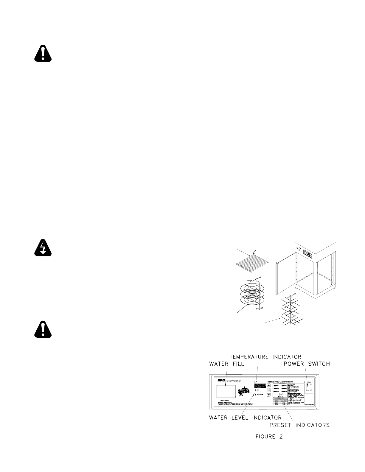
1. Install inside food rack or pizza/pretzel shelves depending on the model
unit purchased. The shelves are in the enclosed accessory carton
(See Figure 1).
2. Plug the unit into a grounded 120 V.A.C. receptacle (230V receptacle for European
models).
LOCATION AND FUNCTION OF CONTROLS
The operating controls are located above the door on the side of the unit next to the water fi ll
(See Figure 2).
1. Temperature Indicator - Displays temperature
2. Water Level Indicators - When ON water level is too low
3. ON/OFF Switch - Activates lights, digital thermometer and air circulation system.
4. Low Water Light - When the light is ON this indicates that water must be added. The fi ll
light will also come on. Element shuts OFF until water is added.
4 175F° 6
5 150F° 5
6 150F° 5
To select Pre-Sets press and hold MODE then press SELECT to toggle through pre-sets.
Stop on the desired pre-set setting. For specifi c food products, see the Recommended
Control Settings and Holding Times section.
c. Temperature and Humidity Programming- A pre-set can be changed. Hold + and - for
3 seconds until the current temperature is displayed. Push + up or - down to set the
desired cabinet temperature. Press MODE to display the humidity setting. Press +
up or - down to set the desired humidity level. A setting of 5 will be about 25% relative
humidity. Press MODE to leave program.
By pressing and holding MODE and then SELECT different pre-sets can be
individually chosen and reset to a specifi c temperature and humidity setting.
(Maximum temperature is 175°F and humidity 10).
NOTE
Using tap water will promote scaling that will eventually
cause clogging of water tubes and prevent the proper
operation of the Humidity Cabinet. The use of distilled
water will prevent scaling inside the water lines of the
cabinet.
Page 6
7. Fill reservoir by lifting reservoir lid and pouring water in until both the fi ll and low water light
should be "OFF" when the tank is full. HFD-2A holds approximately 3 quarts and HFD-3A holds
approximately 5 quarts. Both lights will be off until the water level drops below a specifi ed set
level and the low water light comes on. The water heater will stop operating until water is added.
The fi ll light will be "ON" until the water level reaches the fi ll water indicator probe. 5
quarts. Both lights will be off until the water level drops below a specifi ed set level and
the low water light comes on. The water heater will stop operating until water is added.
The fi ll light will be "ON" until the water level reaches the fi ll water indicator probe.
OPERATING PROCEDURES
1. Turn power switch on.
2. Set desired temperature and humidity or desired pre-set. Allow approximately 20 minutes for
machine to reach proper temperature. (Time will vary depending on temperature setting.)
3. Fill water reservoir.
4. Monitor cabinet temperature via the digital thermometer on the control (See Figure 2).
5. Periodically monitor water level by indicator on control panel (See Figure 2).
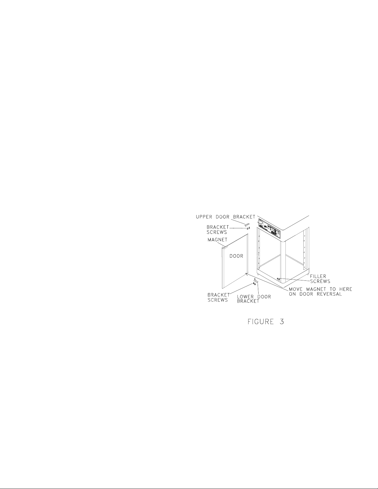
DOOR REVERSAL
Doors are supplied from the factory mounted on the left side of the cabinet but can be mounted
on the right side by following the instructions listed below.
DOOR REMOVAL (See Figure 3)
1. Remove the top left mounting bracket while holding door. Replace screws in holes. Keep the
bracket for installation on the right side.
2. Lift door carefully off of bottom pin bracket
and set down.
3. Remove the bottom pin bracket by
removing the 2 bottom screws. Replace
screws in holes. Keep the bracket for
installation on the right side.
4. For models using the rotating pizza or
pretzel racks only, remove the rectangular
bracket magnet assembly in the upper
right corner of the door being careful not to
crack glass. Slide a razor under to break
adhesive. Keep this assembly because
this will be located in a new position after
the door is moved.
IL1034
DOOR INSTALLATION (See Figure 3)
1. Remove the 2 bottom and 2 top screws on the right side of cabinet door opening.
2. Mount the bottom "taller" mounting pin fi rst and screw in place using the 2 screws removed
earlier.
3. Mount the bottom door hinge hole into the bottom pin, while holding door. The handle should
be on the outside of door on the left side of the unit.
4. Locate the top mounting pin into top door hinge hole. Slide the top bracket into place, holding
door, and attach top bracket using the 2 screws removed earlier.
5. Check door for proper alignment in opening. Door can be adjusted slightly up and down by
sliding the lower bracket back or forth. Door can be adjusted slightly in and out of cabinet by
adjusting top bracket in and out. Tighten all door mounting screws securely.
6. For rotating models, locate the magnet assembly at the top right hand corner of the installed
door. Use RTV silicone to hold it in place. Check for rotisserie operation by opening and
closing door.
Page 7

CLEANING INSTRUCTIONS
WARNING
DISCONNECT ELECTRICAL CORD BEFORE CLEANING
THE CABINET
1. To maintain fi nish and shine of unit, wipe daily with a damp cloth and mild soap. Do not
use harsh detergents or scouring pads.
2. Daily cleaning of inside glass, bottom pan and racking system with a damp cloth is
required.
CAUTION
Be sure cabinet has cooled down prior to opening drain
to avoid burning fi ngers while unscrewing plug.
3. It is required that the water reservoir be drained daily and re-fi lled with fresh water. This
can be done by placing a 5 quart container under the drain plug and un-screwing the
drain plug.
Page 8

TROUBLE SHOOTING GUIDE
This guide is recommended for use by a qualifi ed service technician familiar with electrical
commercial equipment.
1. Unit does not operate.
- Be sure unit is plugged into correct supply voltage.
- Be sure power switch is turned on.
- Disconnect power cord and check power switch and wiring connections for bad connections.
2. Unit turns on but unit light or blower does not come on. Blower and light should always
be on whenever unit is energized.
- If the light is not on, check and replace the light bulb with a standard 75 watt bulb.
- If the blower is not on, turn off power switch and disconnect power cord. Check wiring to blower
motor. Check motor to see if it turns freely. Check motor and replace blower if showing an open
circuit on continuity test.
3. Center rotisserie motor does not work. Motor will turn only when door is closed
completely.
- Check for door magnet on top door glass. This energizes a proximity switch in the unit when the
door is closed. If it is not there it must be replaced to energize motor. If it is there and motor does
not work, try repositioning on door glass to energize motor. If this fails then check rotisserie motor
and wire connections. Also check proximity switch by doing a continuity check on switch with
door closed. If switch is working on a closed door then the rotisserie motor must be checked and
replaced if necessary.
4. Unit turns on, everything works but cabinet does not heat up.
- Check electronic control on top front of unit. Verify that the unit is set for a warmer air temperature
than room temperature. Set it for 140°.
- If unit does not heat up after operating for several minutes, several things must be checked to
determine the cause.
a. With the control set at 140°F, check the power to the air heater element relay from the
control board. It should be about 12 V.D.C. to the relay coil. If it is then the board and the
air temperature thermistor sensor are working. If not then the sensor and board must be
checked. The sensor should read about 4,000-5,000 ohms at room temperature. Resistance
on the probe will drop as the temperature increases. If it reads open then replace it. To
check the board, install a 5,000 ohm 1/2 watt resistor for the suspect sensor. The board
should supply 12 V.D.C. power to the relay. If it doesn't, then the board is defective.
b. If the relay is getting energized by the board and the air heater element is still not working,
check the voltage out of the power side of the relay. It should be 0 VAC. If not, then replace
the relay.
- If relay is working and the wiring is all intact and tightly connected, then the heating element must
be checked.
- Disconnect heating element and check for continuity. You should measure a low ohms reading
like 15-20 ohms. If nothing, then replace heating element.
Page 9

5. Unit turns on, everything works but water heater does not work.
- Check electronic control on the front of unit. Verify that the humidity setting is set for a value of
10 to check control.
- Be sure water tank is fi lled with water and the water fi ll light is off.
- With the unit operating for several minutes the water in the fi ll should be getting warm. If not then
troubleshoot the water heating element following the same steps in 4a. and 4b. on the previous
page, except on the water heater relay, sensor and heating element.
6. Unit turns on, everything works, but the low water light is on. When the low water light
is on and blinking there will be no voltage to the relay or water heating element.
- Check and make sure unit is full of water. If yes, then shut off the power switch and disconnect
power cord. Remove top and check the water sensor board (3 connections on water tank). Remove
sensor board and verify the 2 sensor rods are attached to the underside of board. The long rod
should be attached to the terminal connector marked "L" for low water indicator. The short rod to
the "H" terminal for high water. The green ground wire must be attached to the "G" connection.
Using a fi ne sandpaper, sand both sensing rods to remove any corrosive buildup. Re-attach the
sensor assembly securely using the screws removed. Be sure wires are attached and routed back
correctly to the marked control board terminals. Re-attach the top and energize unit. Low water
light should be off. If not, then control board is not functioning properly and should be replaced.
Page 10

Visit our Website at: www.star-mfg.com Email: service@star-mfg.com
This unit has been tested for proper operation before leaving our plant to insure delivery of your unit in perfect condition. However, there are instances in
which the unit may be damaged in transit. In the event you discover any type of damage to your product upon receipt, you must immediately contact the
transportation company who delivered the item to you and initiate your claim with same. If this procedure is not followed, it may affect the warranty status of
the unit.
All workmanship and material in Star products have a one (1) year limited warranty on parts & labor in the United States and Canada. Such warranty is limited
to the original purchaser only and shall be effective from the date the equipment is placed in service. Star's obligation under this warranty is limited to the repair
of defects without charge, by the factory authorized service agency or one of its sub-agencies. Models that are considered portable (see below) should be taken
to the closest Star service agency, transportation prepaid.
THOROUGHLY INSPECT YOUR UNIT ON ARRIVAL
LIMITED EQUIPMENT WARRANTY
> Star will not assume any responsibility for loss of revenue.
> On all shipments outside the United States and Canada, see International Warranty.
* The warranty period for the JetStar six (6) ounce & Super JetStar eight (8) ounce series popcorn machines is two (2) years.
* The warranty period for the Chrome-Max Griddles is ¿ ve (5) years on the griddle surface. See detailed warranty provided with unit.
* The warranty period for TeÀ on/Dura-Tec coatings is one year under normal use and reasonable care. This warranty does not apply if damage occurs to
TeÀ on/Dura-Tec coatings from improper cleaning, maintenance, use of metallic utensils, or abrasive cleaners, abrasive pads, product identi¿ ers and
point-of-sale attachments, or any other non-food object tha comes in continuous contact with the roller coating. This warranty does not apply to the
“non-stick” properties of such materials.
> This warranty does not apply to "Special Products" but to regular catalog items only. Star's warranty on "Special Products" is six (6) months on parts
and ninety (90) days on labor.
> This warranty does not apply to any item that is disassembled or tampered with for any purpose other than repair by a Star Authorized Service Center or
the Service Center's sub-agency.
> This warranty does not apply if damage occurs from improper installation, misuse, wrong voltage, wrong gas or operated contrary to the Installation and
Operating instructions.
> This warranty is not valid on Conveyor Ovens unless a "start-up/check-out" has been performed by a Factory Authorized Technician.
Parts that are sold to repair out of warranty equipment are warranted for ninety (90) days. The part only is warranted. Labor to replace the part is chargeable to
the customer.
1. Travel time and mileage rendered beyond the 50 mile radius limit
2. Mileage and travel time on portable equipment (see below)
3. Labor to replace such items that can be replaced easily during a daily cleaning
routine, ie; removable kettles on fryers, knobs, grease drawers on griddles, etc.
4. Installation of equipment
5. Damages due to improper installation
6. Damages from abuse or misuse
7. Operated contrary to the Operating and Installation Instructions
8. Cleaning of equipment
9. Seasoning of griddle plates
Star will not honor service bills that include travel time and mileage charges for servicing any products considered "Portable" including items listed below.
These products should be taken to the Service Agency for repair:
* The Model 510FD Fryer.
* The Model 526TOA Toaster Oven.
* The Model J4R, 4 oz. Popcorn Machine.
* The Model 518CMA & 526CMA Cheese Melter.
* The Model 12MC & 15MC & 18MCP Hot Food Merchandisers.
* The Model 12NCPW & 15NCPW Nacho Chip/Popcorn Warmer.
* All Hot Dog Equipment except Roller Grills & Drawer Bun Warmers.
* All Nacho Cheese Warmers except Model 11WLA Series Nacho Cheese Warmer.
* All Condiment Dispensers except the Model HPD & SPD Series Dispenser.
* All Specialty Food Warmers except Model 130R, 11RW Series, and 11WSA Series.
* All QCS/RCS Series Toasters except Model QCS3 & RCS3 Series.
SERVICES NOT COVERED BY WARRANTY
PARTS WARRANTY
10. Voltage conversions
11. Gas conversions
12. Pilot light adjustment
13. Miscellaneous adjustments
14. Thermostat calibration and by-pass adjustment
15. Resetting of circuit breakers or safety controls or reset buttons
16. Replacement of bulbs
17. Replacement of fuses
18. Repair of damage created during transit, delivery, &
installation OR created by acts of God
PORTABLE EQUIPMENT
ALL:
* Pop-Up Toasters
* Butter Dispensers
* Pretzel Merchandisers
(Model 16PD-A Only)
* Pastry Display Cabinets
* Nacho Chip Merchandisers
* Accessories of any kind
* Sneeze Guards
* Pizza Ovens
(Model PO12 Only)
* Heat Lamps
* Pumps-Manual
The foregoing warranty is in lieu of any and all other warranties expressed or implied and constitutes the entire warranty.
FOR ASSISTANCE
Should you need any assistance regarding the Operation or Maintenance of any Star equipment; write, phone, fax or email our Service Department.
In all correspondence mention the Model number and the Serial number of your unit, and the voltage or type of gas you are using.
Part# 2M-4497-2 12/06 RMS
Page 11

S
8
C
10/06/2005
M
N.O.
N.C.
DOOR SWITCH
COM
COM
N.C.
N.O.
PROXIMITY DOOR SWITCH
MOTOR
ROTISSERIE
ONLY
2 DOOR MODELS
M
MOTOR
A
LIGHTED
ON/OFF SWITCH
WATER SENSOR
AIR SENSOR
G GREEN
GROUND
INDICATOR
LOW WATER
L BLACK
H RED
WATER LEVEL SENSOR
INDICATOR
HIGH WATER
E13
E12
E11
E10
GND
LO
CIRCUIT BOARD
HI
LAMP
12 Rev
K1
E4
E6
E5
BLUE
RED
E1
E3
E2
YELLOW
STAR MANUFACTURING INTERNATIONAL INC.
10 V.
AIR
RELAY
N.O.
AIR ELEMENT
COM
WATER
RELAY
N.O.
WATER ELEMENT
120 V.
(240 V)
TRANSFORMER
COM
WHITE
BLK
GND
CORD SET
RED
MOTOR
WHITE
BLUE
M
WHITE
WHITE
M
BLUE
MOTOR
RED
120V CONFIGURATION
WHITE
A
BLACK
230/240V CONFIGURATION
A
BLACK
HFD-2A
MODEL:
NO REPRODUCTION OR DISCLOSURE OF ITS CONTENTS IS PERMITTED.
THIS DRAWING CONTAINS INFORMATION CONFIDENTIAL TO STAR MFG. INT'L. INC.
Page 12

S
8
3
05/06/
00
2
2
N.O.
N.C.
COM
COM
N.C.
N.O.
PROXIMITY DOOR SWITCH
MOTOR
ROTISSERIE
ONLY
DOOR SWITCH
2 DOOR MODELS
M
MOTOR
A
LIGHTED
ON/OFF SWITCH
E13
WATER SENSOR
AIR SENSOR
L
H
G
GROUND
INDICATOR
LAMP
LOW WATER
WATER LEVEL SENSOR
INDICATOR
HIGH WATER
E12
E11
E10
E6
GND
LO
CIRCUIT BOARD
HI
LAMP
Rev B
1
K1
STAR MANUFACTURING INTERNATIONAL INC.
E4
E1
E3
E5
E2
10 V.
COM
C
RELAY
A
N.O.
WATER ELEMENT
TRANSFORMER
BD
(240 V)
120 V.
COM
RELAY
N.O.
AIR ELEMENT
WHITE
BLK
RED
WHITE
BLUE
GND
CORD SET
M
MOTOR
WHITE
BLUE
WHITE
M
MOTOR
HFD-3A
RED
120V CONFIGURATION
WHITE
A
BLACK
230/240V CONFIGURATION
A
BLACK
MODEL:
NO REPRODUCTION OR DISCLOSURE OF ITS CONTENTS IS PERMITTED.
THIS DRAWING CONTAINS INFORMATION CONFIDENTIAL TO STAR MFG. INT'L. INC.
Page 13

INSTALLATION OF RACKS ON HFD-2 MODELS
FRD TO CONTROL PANEL
INSTALLATION OF 3 RACKS
FRD TO CONTROL PANEL
SOME ITEMS ARE INCLUDED FOR
ILLUSTRATIVE PURPOSES ONLY AND IN
CERTAIN INSTANCES MAY NOT BE AVAILABLE
MODEL:
THIS DRAWING CONTAINS INFORMATION CONFIDENTIAL TO STAR MFG. INT'L. INC.
NO REPRODUCTION OR DISCLOSURE OF ITS CONTENTS IS PERMITTED.
HFD-2
STAR MANUFACTURING INTERNATIONAL INC.
SK1858 Rev -
INSTALLATION OF 4 RACKS
04/26/2001
Page 14

21
8
12
51
11
14
16
15
10
13
50
20
8
4
HUMIDITY CABINET
HFD-
2A
WAT
WAT
WHE
ER FILL
ER FI
LIGHTS
N THE WAT
LL
INSTRUC
W
ILL TU
ER LEV
TI
TEMPERATURE/HUMIDITY CONTROL
ONS:
RN ON.
EL BECOME
FILL
FILL
RESER
S LOW,
VOIR
THE "LO
UNTIL B
LOW WATER
W WATE
OTH LIGHTS
MODE
P/S 1
R" AND
"FIL
TURN O
P/S
L"
2
P/
S 4
FF
.
PRE
S
E
P/S 3
T
S
E
LE
-PR
C
T
P/
E
ION:
S
S
S 5
AND H
O
SELE
LD
MO
C
T
D
E
TO
T
T
OGG
H
E
P/
N
FAHR
L
PR
E
S
T
E
E
H
N
S
R
H
S
6
O
E
UG
IT
O
H
PR
R CE
-
S
P
E
R
ESE
E
LECT
LSIU
S
S
T
S
AND H
S
POWER
S
E
L
E
OLD
CT
PRESET 1
MO
I
O
D
PRESET 2
N
T
E
O
:
CH
TH
AN
E
N
T
G
E
PRE
E
MP
T
E
H
RA
ON
SS
E
TURE
S
ET
TIN
PRESET 3
AN
-
G
HOL
D HUM
D
MO
PRESET 4
I
D
D
E
I
T
FLAS
Y
PRO
BREAD PRODUCTS PIZZ
H
ES
GRA
,
PRESET 5
PRESET 6
AND
MM
A
-US
IN
T
G
E
HE
:
CABI
SANDWICH
N
AND
E
T
-PR
T
E
MPE
ES
CHICKEN
S
MO
TO S
R
A
D
TUR
E
ET
E
T
ES
C
IS
O
-
OPTIONAL
OPTIONAL
A
U
BINE
D
DISPLAYE
S
OFF
I
E
SPLA
T
TEM
Y HU
D
PERA
AND
M
ID
-PR
ITY
TURE
E
SE
S
S
SELEC
T
TO
T
I
NG
T
S
ET
TO
MO
H
D
UM
E
S
E
I
T D
DITY
TO E
I
FF
XIT PR
E
R
E
NT
OGR
PR
A
E
M
S
E
FU
T
,
N
O
CTI
R
P
ON
R
E
S
S
17
6
7
6
19
5
4
18
9
This drawing contains information confidential
to Star Manufacturing International, Inc.
No reproduction or disclosure of its
contents is permitted.
SOME ITEMS ARE INCLUDED FOR
ILLUSTRATIVE PURPOSES ONLY AND IN
CERTAIN INSTANCES MAY NOT BE AVAILABLE
MODEL: HFD-2A,-3A
2
3
1
STAR MANUFACTURING INTERNATIONAL, INC.
SK1714 REV. - 10/9/00
Page 15

52
48
47
35
34
23
22
33
38
32
HUMIDITY CABINET
HFD
WATER FILL INSTRUCTIONS:
WHEN THE WATER LEVEL
LIGHTS WILL TURN ON
WATER FI
-2A
LL
BECOME
. FILL RESERVOIR UNTIL BOT
S LOW, THE "LOW WATER" AND "FILL"
H LIGHTS
49
FILL
LOW WATER
TURN OFF.
TEMPE
RATURE/HUMIDITY CONTRO
MODE
PRESET 3
PRESET 4
PRESET 5 PRESET 6
24
37
25
26
36
53
27
P/S 1
P/
S
P
2
/
S
4
PR
L
E
SET
P/S 3
S
E
L
E
P
CTIO
RES
P/S 5
N
S
:
AN
D HO
SE
LD
LE
MODE
C
T
TO
TOG
T
H
EN P
P
G
FAH
/
L
E
S
R
RE
TH
ENHEI
SS
R
6
OU
T
G
H
O
R
-PRES
SELE
PR
C
E
EL
SE
S
S AN
T
IUS
S
C
POWER
T
D
S
ELE
H
O
CTIO
L
PRESET 1
D
MODE
PRESET 2
N
TO
:
CHA
THEN P
NG
TE
E
MP
TH
RE
ER
ON
S
E
ATURE
S
SE
TTIN
AND
G
H
O
LD
H
U
MOD
MI
D
E
ITY P
FL
ASHES
BRE
PIZZA
R
OG
,
R
A
A
AD
M
ND
-USE
MIN
THE
G
:
PRODUCTS
C
A
BI
SAN
N
A
N
ET
D
-PR
TEMP
DWICHES
E
S
ER
CHI
S
MO
TO
ATU
D
E
S
R
ET
CKE
E
IS
TO
CABIN
-U
OPTIONAL
OPTIONAL
DI
D
S
OFF
I
E
SP
S
N
ET
P
LA
L
AYED
TEMP
Y
H
UMI
AND
E
R
DITY SE
ATUR
-PR
E
E
S
S
SE
T
TO
LEC
TIN
T
S
G
ET
TO
MODE
H
U
S
MID
ET
T
ITY
O
D
IFFERENT
EX
I
T
P
ROG
P
RAM
R
ES
ET
F
,
U
NCTIO
OR P
R
N
E
S
S
28
44
45
This drawing contains information confidential
to Star Manufacturing International, Inc.
No reproduction or disclosure of its
contents is permitted.
42
46
43
41
40
29
30
31
39
SOME ITEMS ARE INCLUDED FOR
ILLUSTRATIVE PURPOSES ONLY AND IN
CERTAIN INSTANCES MAY NOT BE AVAILABLE
MODEL: HFD-2A,-3A 120V/230V
STAR MANUFACTURING INTERNATIONAL, INC.
SK1375 REV. E 10/9/00
Page 16

PARTS LIST January 17, 2007 Rev. L
HFD2A and HFD3A HUMIDIFIED CABINET
MODEL
Number
Key
Number
1 C3-G8021 1 CORD ASSEMBLY HFD-2A
2E-05-07-0169 1 CORD ASSEMBLY HFD-3A
A4-120165 1 CORD ASSEMBLY (230V)
2 2K-Y2968 1 BUSHING - STRAIN RELIEF
3 2A-6904 4 FOOT
4 D5-Y9623 6/4 GLASS CHANNEL HFD-2A
2I-Y7838 6/4 GLASS CHANNEL HFD-3A
5 2Q-Y9567 3/2 GLASS - SIDE HFD-2A / -2APT
2Q-Y9110 2 GLASS - SIDE HFD-3A / -3APT
2Q-Y9121 1 GLASS - BACK HFD-3A
6 D5-Y9624 6/4 GLASS CHANNEL HFD-2A
2I-Y7840 6/4 GLASS CHANNEL HFD-3A
7 2K-Y1139 1 BUSHING - HEYCO
8 2I-Y7839 2 GLASS CHANNEL-TOP AND BOTTOM HFD-3A
9 D5-220038 1 BOTTOM ASSEMBLY HFD-2A
D5-220029 1 BOTTOM ASSEMBLY HFD-3A
10 D5-HFD004 1 WATER FILL ASSEMBLY
11 2C-Z3389 1 NUT, WATER FILL ASSEMBLY
12 D5-Z3401 1 TOP COVER HFD-2A
D5-Z3409 1 TOP COVER HFD-3A
13 2M-Z4180 1 LABEL-OPERATOR PANEL HFD-2A
2M-Z4181 1 LABEL-OPERATOR PANEL HFD-3A
14 D5-HFD014 1/2 TOP DOOR BRACKET ASSEMBLY
15 D5-HFD032 1/2 GLASS DOOR ASSEMBLY w/ MAGNET HFD-2A / -2APT
D5-HFD033 1/2 GLASS DOOR ASSEMBLY w/ MAGNET HFD-3A / -3APT
NI 2R-Z3494 1 MAGNET, DOOR
16 D5-HFD017 1/2 BOTTOM DOOR BRACKET ASSEMBLY
17 D5-Z3573 1 BOTTOM REAR - CUSTOMER HFD-2A
D5-Z3418 1 BOTTOM REAR - CUSTOMER HFD-3A
18 D5-Z3417 1 BOTTOM WRAP - OPERATOR HFD-2A
D5-Z3574 1 BOTTOM WRAP - OPERATOR HFD-3A
19 D5-HFD034 1/2 DOOR SWITCH BRACKET ASSEMBLY
20 2E-Z3392 1 SWITCH ON/OFF
21 D5-Z3729 2/4 DOOR STOP FILLER HFD-2A
D5-Z3730 2/4 DOOR STOP FILLER HFD-3A
22 2E-Z3236 2 THERMISTER SENSOR
23 D5-HFD003 1 WATER LEVEL SENSOR ASSEMBLY
24 2U-Z3641 1 ROTISSERIE MOTOR (120V), Fan Blade Not Included
2U-Z3642 1 ROTISSERIE MOTOR (230V), Fan Blade Not Included
NI 2U-Z9811 1 FAN BLADE, MOTOR
25 2N-Y9145 1 AIR HEATER (120V) HFD-2A
2N-Z0628 1 AIR HEATER (230V) HFD-2A
2N-Z3678 1 AIR HEATER (120V) HFD-3A
2N-Z4150 1 AIR HEATER (230V) HFD-3A
26 2U-Z3412 1 BLOWER (120V/230V)
27 A3-35219 1 CAP AND CHAIN
28 2E-05-07-0352 2 RELAY
29 2E-05-07-0351 1 TRANSFORMER (120V)
2E-05-07-0350 1 TRANSFORMER (230V)
30 D5-Z3543 1 CONTROL MOUNTING BRACKET
Part
Number
Per
Unit
Description and Model Designation
IMPORTANT: WHEN ORDERING, SPECIFY VOLTAGE OR TYPE GAS DESIRED PAGE 1
INCLUDE MODEL AND SERIAL NUMBER OF 2
Some items are included for illustrative purposes only and in certain instances may not be available.
Star Manufacturing International, Inc.
Page 17

PARTS LIST January 17, 2007 Rev. L
HFD2A and HFD3A HUMIDIFIED CABINET
MODEL
Key
Number
31 2E-Z3287 1 CONTROL BOARD (120V/230V)
32 2S-Z3608 1/2 BULB - STANDARD 75 WATT (120V) HFD-2A / HFD-3A
2S-Z0630 1 BULB - STANDARD 100 WATT (230V)
33 2E-Y9184 1 SOCKET
34 D5-Z3396 1 COVER RESERVOIR HFD-2A
D5-Z3406 1 COVER RESERVOIR HFD-3A
35 D5-HFD007 1 RESERVOIR ASSEMBLY HFD-2A
D5-HFD008 1 RESERVOIR ASSEMBLY HFD-3A
36 D5-Z3399 1 FRONT AIR DUCT HFD-2A
D5-Z3410 1 FRONT AIR DUCT HFD-3A
37 D5-Z3400 1 COVER AIR DUCT HFD-2A
D5-Z3408 1 COVER AIR DUCT HFD-3A
38 D5-Z4435 1 DOOR RACK ANGLE-LEFT HFD-2A
D5-Z0285 1 DOOR RACK ANGLE-LEFT HFD-3A
39 D5-Z4437 1 RACK ANGLE-LEFT HFD-2A
D5-Z0309 1 RACK ANGLE-LEFT HFD-3A
40 D5-Z4436 1 DOOR RACK ANGLE-RIGHT HFD-2A
D5-Z0286 1 DOOR RACK ANGLE-RIGHT HFD-3A
41 D5-Z4438 1 RACK ANGLE-RIGHT HFD-2A
D5-Z0310 1 RACK ANGLE-RIGHT HFD-3A
42 D5-220055 1 PRETZEL SHAFT HFD-2A
D5-220058 1 PRETZEL SHAFT HFD-3A
43 2B-Z7205 3 PRETZEL HOLDER HFD-2A
2B-Z7206 4 PRETZEL HOLDER HFD-3A
44 2B-Z4279 3 PIZZA SHELF HFD-2A
2B-Z4280 4 PIZZA SHELF HFD-3A
45 2B-Z8982 1 PIZZA SHAFT HFD-2A
2B-Z8983 1 PIZZA SHAFT HFD-3A
46 2C-Z0812 1 HAIRPIN
47 2B-Z0289 3 SHELF HFD-2A
2B-Z0290 4 SHELF HFD-3A
48 2E-Z3393 1 UPPER WIRE HARNESS HFD-2A
2E-Z3394 1 UPPER WIRE HARNESS HFD-3A
49 2N-Z3435 1 CARTRIDGE HEATER 120V
2N-Z4149 1 CARTRIDGE HEATER 230V
50 D5-Z3402 1 TOP WRAP - OPERATOR HFD-2A
D5-Z3411 1 TOP WRAP - OPERATOR HFD-3A
51 D5-Y9591 1 TOP WRAP - CUSTOMER HFD-2A
D5-Y9741 1 TOP WRAP - CUSTOMER HFD-3A
52 1P-E1525 FOAM GASKET TAPE
53 2E-Z3713 1/2 PROXIMITY SWITCH - DOOR
54 2M-Z4187 1 TOP GRAPHIC LABEL - FRESH & FAST (not shown) HFD-2A
2M-Z4188 1 TOP GRAPHIC LABEL - FRESH & FAST (not shown) HFD-3A
55 2Q-Y9212 1 GLASS BACK HFD-3A
Part
Number
Per
Unit
Description and Model Designation
Number
IMPORTANT: WHEN ORDERING, SPECIFY VOLTAGE OR TYPE GAS DESIRED PAGE
2
INCLUDE MODEL AND SERIAL NUMBER OF
Some items are included for illustrative purposes only and in certain instances may not be available.
Star Manufacturing International, Inc.
2
Page 18

Page 19

Page 20

STAR MANUFACTURING
10 Sunnen Drive, St. Louis, MO 63143 U.S.A.
(800) 807-9054 (314) 781-2777
Parts & Service (800) 807-9054
www.star-mfg.com
 Loading...