

STA-RITE Posi Clear PXC95, Posi Clear PXC75, Posi Clear PXC150, Posi Clear PXC125 Owner's Manual
Posi Clear
TM
Cartridge Filters
Models PXC75, PXC95, PXC125 and PXC150
O W N E R’ S M A N U A L
INSTALLATION, OPERATION & PARTS
Sta-Rite Pool/Spa Group
293 Wright Street, Delavan, WI 53115
International: 262-728-5551, FAX: 262-728-7550
www.starite.com
Union City, TN • Delavan, WI • Mississauga, ON
© 2005, Sta-Rite Industries S620 (Rev. 12/5/05)
This manual should be furnished to
the end user of this filter; its use will
reduce service calls and chance of
injury and will lengthen filter life.
PUSH
E
N
G
L
I
S
H
F
R
A
N
Ç
A
I
S
E
S
P
A
Ñ
O
L
SH
PUSH
PU
PUSH
PUSH
2
Table of Contents
Specifications .............................................................2
Safety Instructions.......................................................3
General Information ...................................................3
Installation..................................................................4
Initial Startup ..............................................................4
Filter Disassembly / Assembly .....................................5
Cartridge Cleaning Procedure .....................................6
System Inspection/Winterizing ....................................6
Troubleshooting Guide ...............................................7
Repair Parts List ..........................................................8
Warranty ....................................................................9
SPECIFICATIONS
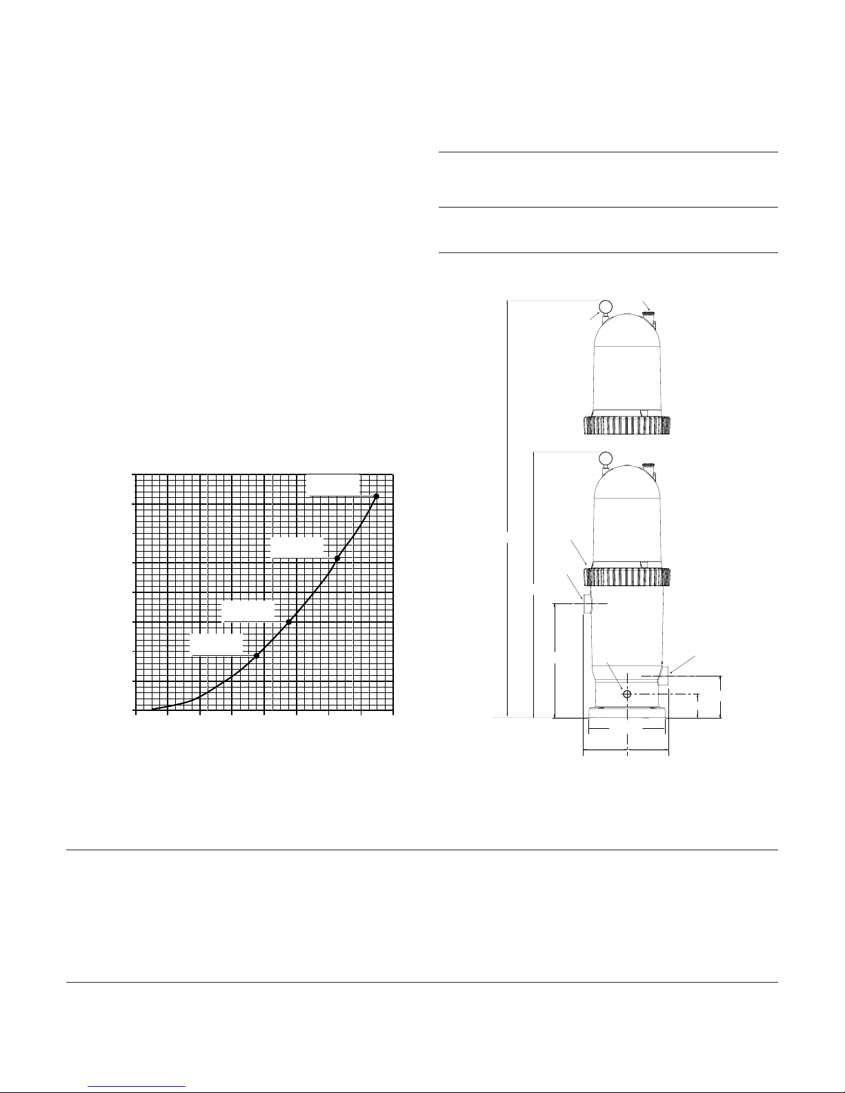
FIGURE 1 – Dimensions in inches (mm)
Pressure Drop Curve for all PXC Models.
Table 2 - Filter Specifications
Model No.
PXC75 PXC95 PXC125 PXC150
Filter Area sq. ft. (m2) 75 (6.96) 95 (8.8) 125 (11.6) 150 (13.9)
Max. Residential Flow Rate GPM (LPM)* 75 (284) 95 (360) 125 (473) 150 (568)
Max. Public Pool Flow Rate GPM (LPM) 28 (106) 36 (132) 47 (177) 56 (212)
Max. Operating Pressure PSI (kPa) 50 (345) 50 (345) 50 (345) 50 (345)
Max. Continuous Water Temperature F(C) 104° (40°) 104° (40°) 104° (40°) 104° (40°)
* NSF listing is for public pool flow rates only.
Table 1 - Filter Dimensions in inches (mm)
Model No.
PXC75 PXC125
Dimension PXC95 PXC150
A 36 (914) 51 (1,295)
B 31 (787) 40 (1,016)
Air Release
Minimum
Service
Height
Pressure
Gauge
Valve
8(55.2)
7(48.3)
6(41.4)
5(34.5)
4(27.6)
3(20.7)
Pressure Drop in PSI (kPa)
2(13.8)
1(6.9)
0(0)
0
(0)
20
(76)40(151)60(227)80(303)
PXC95
Max Flow
PXC75
Max Flow
Flow in GPM (LPM)
PXC150
Max Flow
PXC125
Max Flow
100
(379)
120
(454)
140
(530)
160
(606)
TM
B
Posi-Ring
Inlet
2" NPT
18"
3/4" Drain
12" Dia.
6-7/8"
6-35/64"
Outlet
2" NPT
3-3/4"
A
6-37/64"
3
READ AND FOLLOW SAFETY
INSTRUCTIONS!
This is the safety alert symbol. When you see this
symbol on your filter or in this manual, look for
one of the following signal words and be alert to the
potential for personal injury.
warns about hazards that will cause death,
serious personal injury, or major property damage if
ignored.
warns about hazards that can cause death,
serious personal injury, or major property damage if
ignored.
warns about hazards that will or can cause
minor personal injury or property damage if ignored.
NOTICE indicates special instructions not related to
hazards.
Carefully read and follow all safety instructions in this
manual and on equipment. Keep safety labels in good
condition; replace if missing or damaged.
Hazardous Pressure. Incorrectly installed or
tested equipment may explode, causing severe injury or
property damage. Read and follow instructions in owner’s
manual when installing and operating equipment. Have a
trained pool professional perform all pressure tests.
Do not connect filter to compressed air under any
circumstances.
Do not connect system to a city water system or
other external source of pressurized water.
Do not connect filter to pumps capable of exceeding 50 PSI (345 kPa) maximum pressure.
Open air release valve to vent all air from system
before operating the system.
Risk of falls and injury. Filter surface is slippery. Do not allow children to stand or play on filter.
GENERAL INFORMATION
When to Clean the Filter: The filter cartridge should normally be cleaned when the pressure gauge reading increases 10 PSI over the start-up pressure.
In some pools, accessories such as fountains or pool
cleaners may be noticeably affected by the normal decrease in flow as the filter becomes dirty. If so, clean the
filter more frequently (that is, at a pressure increase of
less than 10 PSI) in order to maintain the required flow.
Clean a new pool as well as possible before filling pool
and operating filter.
A typical pool installation will require approximately
one week to obtain and maintain the sparkle that your
filter is capable of giving you.
Maximum pressure is 50 PSI (345 kPa). DO NOT connect the filter to a city water system or to an individual
water well system.
The Sta-Rite cartridge filter is designed to filter water for
swimming pools and hot tubs only. On a new installation, we recommend:
1. Disassemble the filter after the initial cleanup. Follow
"Filter Disassembly/Assembly Procedure" on Page 5.
2. Remove and hose down the cartridge to remove
contaminants.
Maintain pool water pH between 7.2 and 7.6.
Make sure that the Posi-Ring™ is securely locked in
place before operating filter.
Maintain the pressure gauge in good working order.
Replace a damaged gauge immediately.
Cleaning interval is based on pressure rise, not on
the length of time the filter is operated. Different
water conditions will have different normal cleaning
intervals.
NOTICE: Some pool disinfectants may clog the filter cartridge. To maximize cartridge life and filter cycle time,
closely follow the disinfectant manufacturer’s instructions
when cleaning pool or filter. Failure to follow these instructions may affect warranty coverage of the cartridge.
INSTALLATION
Filter mount must:
Provide weather and freezing protection.
Provide space and lighting for easy access for routine
maintenance. (See Figure 1 for space requirements.)
Provide ventilation and drainage for pump.
Be on a reasonably level surface and provide adequate
drainage.
Piping:
NOTICE: Make sure that the filter and all piping can be
drained for winterizing. See “Winterizing”, Page 6.
NOTICE: Overtightening can crack filter ports.
Use teflon tape, Plasto-Joint Stik®1, or Silastic RTV #732
®
on all threaded connections of plastic pipe and fittings.
DO NOT use pipe compounds on filter; it will cause the
connection to crack. Do not use sealant on unions – assemble them dry and hand tight.
Support pipe independently to prevent strains on filter.
Keep piping tight and free of leaks: pump suction line
leaks may cause trapped air in filter tank or loss of prime
at pump.
1
Lake Chemical Co., Chicago, IL
Electrical:
BE SURE pump grounding meets local and National
Electrical Code standards. All wiring and grounding of associated equipment must meet local and National
Electrical Code Standards.
INITIAL START-UP
Be sure pump is OFF before starting procedure.
Do not operate filter at more than 50 PSI
(345 kPa).
1. Securely lock the Posi-Ring™ in place by rotating it
CLOCKWISE until it “clicks” past the safety latch (see
Figure 3). Stop turning as soon as the ring clicks past the
latch. The ring may feel slightly loose, but it will tighten
up when pump is on and filter is under pressure.
2. Install the pressure gauge and the air release valve
(See Figure 3) on the tank lid.
3. Fill the trap on the pump with water.
4. Open the air release valve on top of the filter.
5. Open valves separating filter from the rest of the
system.
6. Start the pump to purge air from the system.
7. When a steady stream of water comes from the air
release valve, close the valve.
NOTICE: Leaking around the Posi-Ring™ may indi-
cate that the ring is not fully locked. In this case, proceed as follows:
A. Stop the pump and open the air release valve to
release any pressure within the filter.
B. Remove the drain plug and drain all water from
the filter.
C. Rotate the Posi-Ring™ clockwise until it locks be-
hind the safety latch (see Figure 3).
4
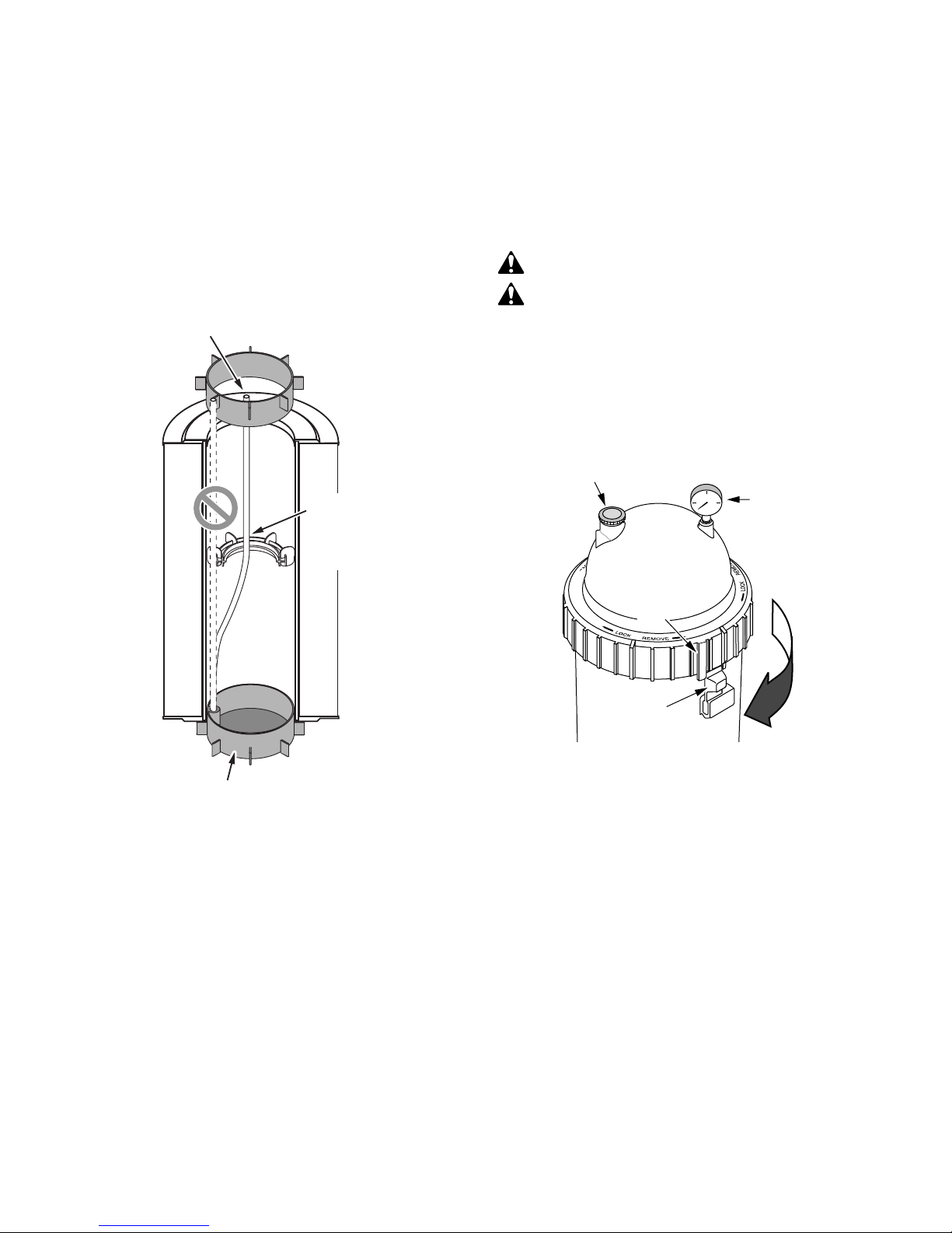
Figure 3 – Rotate Posi-Ring™ until tab locks behind
the safety latch.
FIGURE 2 – Assemble Air Bleed Tube as shown.
Air Bleed tube must
go inside pilot ring
in lid.
Tube must go
through center of
support assembly
in cartridge.
Pilot ring in Base.
4153 0302
Air Release
Valve
Pressure
Gauge
Ta b
PUSH
PUSH
Latch
5
D. If the ring was already locked, remove it and the fil-
ter lid assembly. Inspect and clean the O-ring and all
sealing surfaces. Relubricate the O-ring, if necessary.
NOTICE: Lubricate the O-ring sealing area inside the
upper tank lip with silicone grease, as other lubricants
may cause the ring to swell. DO NOT lubricate the PosiRing™ or the threads on tank shell as this may collect
grit and make removal difficult.
After the filter is operating, record the filter pressure
gauge reading in the owner's manual for future use.
FILTER DISASSEMBLY/
ASSEMBLY PROCEDURE
Before disassembling filter:
1. STOP PUMP.
2. OPEN air release valve and drain fitting.
3. WAIT until all pressure is released and water drained
from filter tank and system before loosening Posi-Ring™.
Disassembly:
1. Stop the pump.
2. Open air release valve on top of filter tank to release
all pressure from inside of tank.
3. Remove the drain cap and drain all water from the tank.
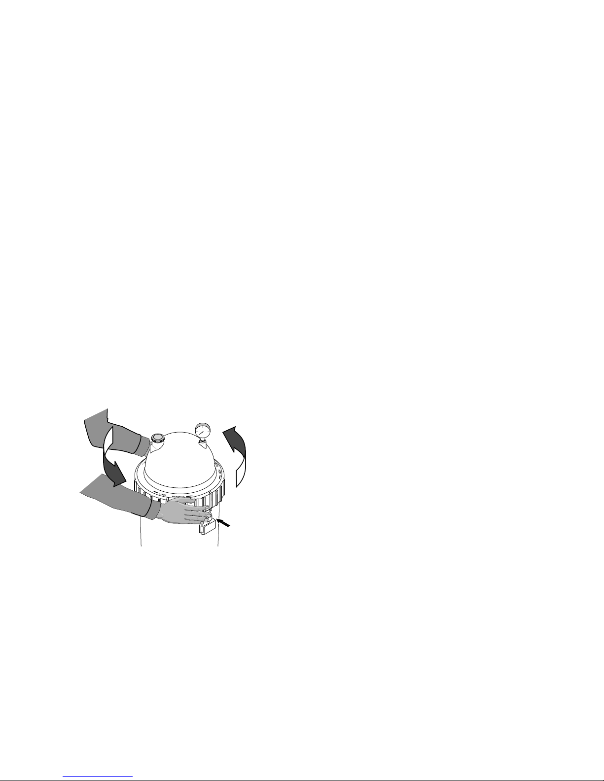
4. Remove filter lid assembly as follows:
a. Press the safety latch (below the ring) toward the
tank to release it (see Figure 4).
b. Hold the latch in the release position and rotate the
ring COUNTERCLOCKWISE to remove it. If the ring
is difficult to turn, tap it gently with a rubber mallet
to overcome initial resistance.
5. Inspect the O-ring for cuts, cracking, deformation or
signs of wear; replace if necessary.
NOTICE: Do not remove the O-ring unless you need
to replace it. To remove it, hook it out of its groove with
a stiff curved piece of wire inserted through the small
access slot in the bottom of the tank lid assembly.
SAFETY LATCH
The purpose of the safety latch is to hold the Posi-Ring™
in the locked position. If the latch is damaged, replace it
as follows:
1. Press up on the small catch on the bottom of the safety
latch and press or tap the latch out of the slot in the tank.
2. Slide the new latch into position until it latches in
place.
NOTICE: DO NOT operate the filter if the safety latch
is damaged or will not hold the Posi-Ring™ in the
locked position.
Assembly:
1. Inspect and clean the tank, ring threads and O-ring
groove. Replace damaged parts as necessary.
2. Install the filter cartridge in the tank. Push down firmly
to seal it.
NOTICE: Lubricate the O-ring sealing area inside the
upper tank lip with silicone base grease, as other lubricants may cause the ring to swell. DO NOT lubricate the Posi-Ring™ or the threads on the tank shell
as this may collect grit and make removal difficult.
3. Install the O-ring in the tank lid assembly O-ring
groove. Be sure that the O-ring is clean and not
twisted.
NOTICE: Do not remove the O-ring unless you need
to replace it.
4. Place the Posi-Ring™ squarely over the tank shell
threads and rotate it CLOCKWISE until it is securely
latched.
5. Follow instructions in the “Initial Startup” section of
this manual.
Figure 4 – Depress safety latch to unscrew the
Posi-Ring™.
H
H
S
S
U
U
P
P

6
CARTRIDGE CLEANING PROCEDURE
When to Clean the Filter: The filter cartridge should normally be removed and cleaned when the pressure gauge
reading increases 10 PSI over the start-up pressure.
Follow all steps in the “Disassembly” section of this
manual (Page 5).
NOTICE: When sanitizing your pool using PHMB (polyhexamethylene biquanide based) cleaners, use
only
PHMB cleaners to clean the cartridge. When using
PHMB sanitizers, the filter cartridge MUST be cleaned
more thoroughly and frequently than for a pool using
chlorine. Follow manufacturer’s instructions carefully.
Use of any other type of cleansers with PHMB pool sanitizers will void the filter’s warranty.
1. Remove the drain cap and flush all foreign material from
the inside of the tank before removing the filter cartridge.
2. Allow the tank to drain.
3. Lift out the cartridge and hose it down thoroughly. Spray
the entire cartridge surface. Allow cartridge to drain.
4. Inspect the cartridge. If necessary, repeat the washing
operation. If the cartridge is damaged, replace it.
5. Follow all steps in the “Assembly” (Page 5) and “Initial
Startup” (Page 4) sections of this manual.
NOTICE: When this procedure no longer adequately
cleans the cartridge, discard the cartridge and replace it
with a new one.
SYSTEM INSPECTION
General:
NOTICE: DO NOT use solvents to clean the filter; sol-
vents may damage plastic components in the system.
NOTICE: Open the air release valve and bleed all air
from the filter each time the pump is stopped and
restarted.
Weekly Inspection:
1. Remove debris from the pool skimmer basket.
2.
Stop the pump; open the air release valve to release all
pressure.
3. Remove the pump trap cover and basket; remove debris.
4. Check the pump for leaks. If found, see the pump
owner's manual.
5. Replace the trap basket and the cover. Tighten the
cover securely hand tight. DO NOT use a lid wrench
to tighten it.
6. Start the pump. When the filter air release valve runs
a solid stream of water, close the valve.
7. When the system has returned to normal operation,
check the filter pressure. If the filter pressure is 10 PSI
(69kPa) or more higher than the initial startup pressure, the filter needs cleaning. See “Cartridge
Cleaning Procedure”, at left.
WINTERIZING
NOTICE: Protect the filter from freezing. Allowing the filter to freeze will damage it and will void the warranty. If
possible, take the system indoors for storage.
1. Clean the filter according to instructions (left) before
winterizing.
2. Stop the pump.
3. Open the air release valve; open any system valves.
4. Remove the drain plugs from the trap, pump, and filter.
5. Gravity drain system and filter as far as possible.
6. Disassemble the filter (follow instructions under “Filter
Disassembly”, Page 5). Remove the filter cartridge
and store it in a warm, dry area.
7. Cover the filter with plastic or tarpaulin to prevent
water entrance and freezing.

7
1. Short Cycle Time:
NOTICE: Cycle Time will vary with each installation
and between different areas of the country. The following causes and remedies are for cycle times shorter
than normal for your area.
A. Chlorine residual too low; maintain proper
residual (consult pool professional for
recommendation).
B. Filter cartridge is dirty or plugged; thoroughly clean
the filter (see No. 4, “Plugged Cartridge”, and
“Cartridge Cleaning Procedure", Page 6).
C. Water is chemically out of balance; consult pool
professional.
D. Algae in the pool. Apply heavy dose of chlorine
or algicide as recommended by the pool
manufacturer.
E. Replace the cartridge.
2. Low Flow/High Pressure:
A. Cartridge plugged; clean filter thoroughly (see Page 6).
B. Pipe blocked downstream from filter; remove
obstruction.
C. Piping too small; use larger pipe (consult dealer for
sizing).
3. Low Flow/Low Pressure:
A. Plugged pump or plugged hair and lint trap; clean
thoroughly.
4. Plugged Cartridge:
A. Insufficient cleaning; follow cleaning instructions
closely and clean thoroughly (see Page 6).
B. Water is chemically out of balance; consult pool
professional.
C. Excessive air in filter. Vent air from tank and check
for pump suction pipe leaks. Clean air bleed tube in
cartridge assembly.
D. Pool water contains iron. Consult your pool
professional.
E. Heavy or improper application of powdered chlo-
rine tablets using a binder. Consult your pool
professional.
F. Algae in the pool. Apply heavy dose of chlorine or
algicide as recommended by the pool
manufacturer.
G. Use of incorrect chemicals with PHMB sanitizers.
Replace filter cartridge.
H. Replace the cartridge.
5. Pool Water Not Clean:
A. Chlorine residual too low; maintain adequate chlo-
rine residual (consult pool service technician for
recommendation).
B. Filter cartridge torn, plugged, or punctured;
replace cartridge.
C. Pool water contains iron. Consult your pool
professional.
D. Heavy or improper application of powdered chlo-
rine tablets using a binder. Consult your pool
professional.
E. Algae in the pool. Apply heavy dose of chlorine
or algicide as recommended by the pool
manufacturer.
F. Replace the cartridge.
6. Pool Cleaner Stops Working:
A. Clean filter and observe performance of pool
cleaner.
B. If pool cleaner performs better after filter has been
cleaned, use a shorter cleaning cycle for the filter
(that is, clean the filter after a pressure rise of less
than 10 PSI).
TROUBLESHOOTING GUIDE
8
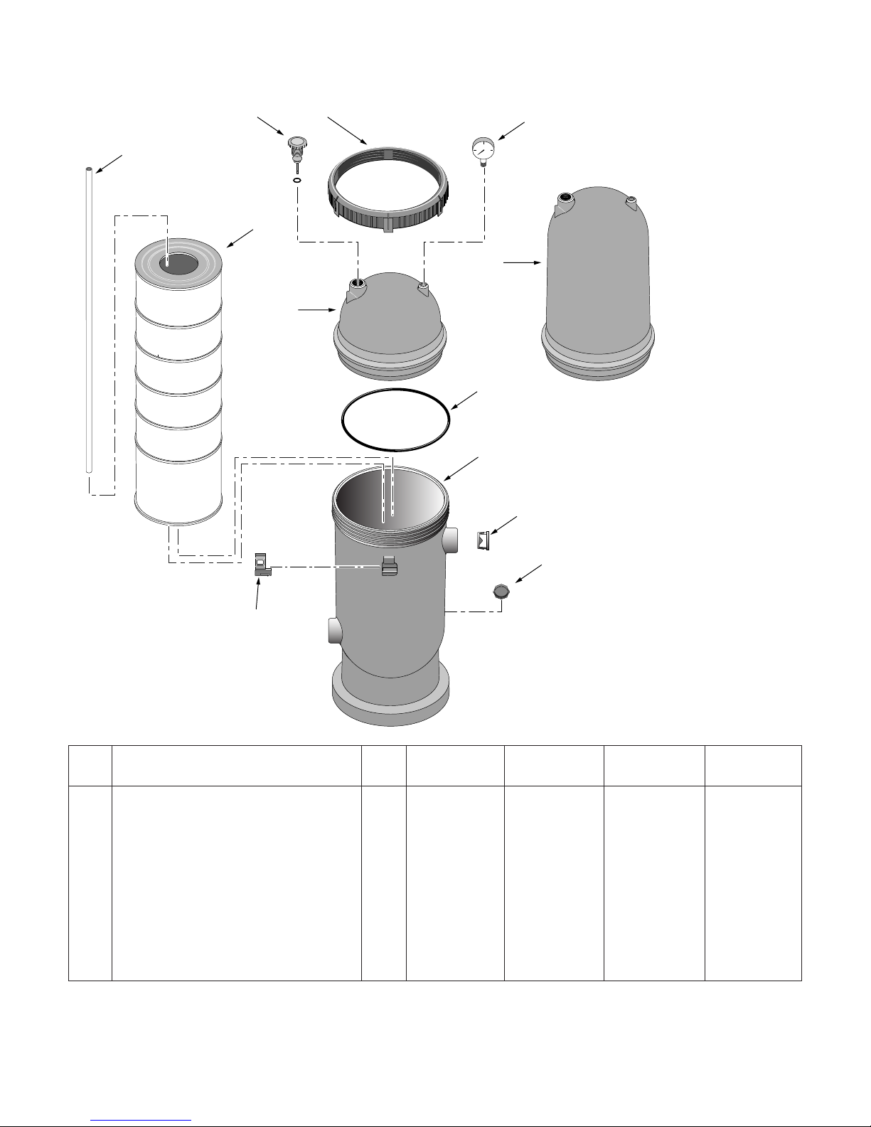
10
Key
No. Description Qty. PXC75 PXC95 PXC125 PXC150
1 Pressure Gauge 1 15060-0000T 15060-0000T 15060-0000T 15060-0000T
2 Filter Lid Assembly* 1 25230-0102S 25230-0102S 25230-0103S 25230-0103S
3 Tank O-Ring† 1 25230-0010S 25230-0010S 25230-0010S 25230-0010S
4 Tank Body 1 25230-0001S 25230-0001S 25230-0001S 25230-0001S
5 Water Diverter 1 25230-0006 25230-0006 25230-0006 25230-0006
6 Drain Cap with Gasket 1 32185-7074 32185-7074 32185-7074 32185-7074
7 Safety Latch 1 25200-0007 25200-0007 25200-0007 25200-0007
8 Filter Cartridge 1 25230-0075S 25230-0095S 25230-0125S 25230-0150S
9 Air Bleed Tube 1 25230-0007 25230-0007 25230-0008 25230-0008
10 Air Release Valve with O-Ring 1 24206-0103S 24206-0103S 24206-0103S 24206-0103S
11 Locking Ring (not sold separately) 1 – – – –
REPAIR PARTS
PXC75
PXC95
PXC125
PXC150
* Includes Key Nos. 2, 3 and 11.
† Includes silicone grease.
9
11
1
8
2
(PXC125,150)
2
(PXC75,95)
3
4
5
PUSH
7
6
4084 1001
CREATE A RECORD OF YOUR WARRANTY AT STA-RITE:
• Complete a warranty registration at www.staritepool.com by clicking on “Register Products” and selecting Sta-Rite Pool
OR
• Complete bottom portion completely and mail within 10 days of installation to Sta-Rite, Attn.: Pool Warranty Dept., 293 Wright St., Delavan , WI 53115
Warranty Registration Card
Name
Address
City State Zip
Installation (or Purchase) Date
Product Purchased
Model Number
■■ New installation ■■ Replacement
Years pool has been in service ■■ less than 1 ■■ 1-3 ■■ 3-5 ■■ 5-10
This product was purchased from:
Company name
Address
City State Zip
STA-RITE LIMITED WARRANTY
For technical information about this product, contact the installer or call Sta-Rite at 262-728-9181.
Visit www.staritepool.com
• for more information about Sta-Rite products listed above
• to locate a Sta-Rite dealer near you
Product Specific Warranties (from date of installation)
Product Limited
Family Warranty Exceptions
Filters 1 Year System 3 Tank Bodies - 10 Yrs
Filter Valves 1 Year
Pumps 1 Year
Heaters 2 Years *Commercial Application - 1 Yr
Controls 1 Year
Above Ground Systems 1 Year
Lights and Niches 1 Year Lamps and Bulbs - 90 Days
White Goods 1 Year
Maintenance Equipment 90 Days
Drainer/Utility Pumps 90 Days
Replacement Parts 90 Days
Cleaners: Lil Shark 1 Year
Cleaners: Calypso 1 Year
Cleaners: Pool Shark 2 Years Footpad and Seal Flaps - 1 Yr
Cleaners: Great White 2 Years
* Commercial and multi-family application.
Retain this warranty certificate in a
safe and convenient location for your records.
Pumps, filters, skimmers, underwater lights (excluding bulbs), accessories and fittings manufactured by Sta-Rite are warranted to
be free of defects in material and/or workmanship for one (1) year
from the original date of installation.
The foregoing warranties relate to the original consumer purchaser
(“Purchaser”) only. Sta-Rite Industries shall have the option to repair or replace the defective product, at its sole discretion.
Purchasers must pay all labor and shipping charges necessary to
replace the product covered by this warranty. Requests for warranty service must be made through the installing dealer. This warranty shall not apply to any product that has been subject to
negligence, misapplication, improper installation or maintenance,
or other circumstances which are not in Sta-Rite’s direct control.
Failure to have product installed by a professional in compliance
with local codes will void any and all manufacturer’s warranties.
This warranty sets forth Sta-Rite’s obligation and Purchaser’s exclusive remedy for defective products.
STA-RITE SHALL NOT BE LIABLE FOR ANY CONSEQUENTIAL,
INCIDENTAL OR CONTINGENT DAMAGES WHATSOEVER.
THE FOREGOING WARRANTIES ARE EXCLUSIVE AND IN
LIEU OF ALL OTHER EXPRESS WARRANTIES. IMPLIED WARRANTIES, INCLUDING BUT NOT LIMITED TO THE IMPLIED
WARRANTIES OF MERCHANTABILITY AND FITNESS FOR A
PARTICULAR PURPOSE, SHALL NOT EXTEND BEYOND THE
DURATION OF THE APPLICABLE EXPRESS WARRANTIES
PROVIDED HEREIN.
Some states do not allow the exclusion or limitation of incidental or
consequential damages or limitations on how long an implied warranty lasts, so the above limitations or exclusion may not apply to
you. This warranty gives you specific legal rights and you may also
have other rights which vary from state to state.
Supersedes all previous publications.
S4877PS (Rev. 7/21/04)

10
 Loading...