

Page 1
OWNER’S MANUAL
Self-Priming
Centrifugal Pumps
© 2005, Sta-Rite Industries S976 (Rev. 8/8/05)
293 Wright Street, Delavan, WI 53115
“D” Series
Installation/Operation/Parts
For further operating, installation,
or maintenance assistance:
Call 1-262-728-5551
Page 2
Safety 2
READ AND FOLLOW
SAFETY INSTRUCTIONS!
This is the safety alert symbol. When you see this
symbol on your pump or in this manual, look for
one of the following signal words and be alert to the
potential for personal injury:
warns about hazards that will cause serious
personal injury, death or major property damage if
ignored.
warns about hazards that can cause serious
personal injury, death or major property damage if
ignored.
warns about hazards that will or can cause
minor personal injury or property damage if ignored.
The label NOTICE indicates special instructions which
are important but not related to hazards.
Carefully read and follow all safety instructions in this
manual and on pump.
Keep safety labels in good condition.
Replace missing or damaged safety labels.
Make workshops childproof; use padlocks and master
switches; remove keys.
GENERAL SAFETY
Do not touch an operating motor. Modern
motors are designed to operate at high temperatures. To
avoid burns when servicing pump, allow it to cool for 20
minutes after shut-down before handling.
Do not allow pump or any system component to freeze.
To do so will void warranty.
Pump water only with this pump.
Periodically inspect pump and system components.
Wear safety glasses at all times when working on pumps.
Keep work area clean, uncluttered and properly lighted;
store properly all unused tools and equipment.
Keep visitors at a safe distance from the work areas.
Pump body may explode if used as a
booster pump unless relief valve capable of passing full
pump flow at 75 psi is installed.
WARNING
Hazardous pressure!
Install pressure relief
valve in discharge pipe.
Release all pressure on
system before working on
any component.
WARNING
Hazardous voltage.
Can shock, burn, or
cause death.
Ground pump before
connecting to power
supply. Disconnect power
before working on pump,
motor or tank.
Wire motor for correct
voltage. See “Electrical”
section of this manual and
motor nameplate.
Ground motor before
connecting to power
supply.
Meet National Electri-
cal Code, Canadian
Electrical Code, and local
codes for all wiring.
Follow wiring instruc-
tions in this manual
when connecting motor to
power lines.
Page 3

Table of Contents 3
Thank you for purchasing a top quality, factory tested pump.
Page
General Safety .....................................................................................................2
Warranty..............................................................................................................3
Installation........................................................................................................4-5
Electrical...........................................................................................................6-7
Service ...........................................................................................................8-10
Repair Parts ..................................................................................................11-12
LIMITED WARRANTY
Sta-Rite Industries warrants to the original consumer of the products listed below, that they will be free from defects in material
and workmanship for the Warranty Period from the date of original installation or manufacture as noted.
Product Warranty Period
Water Systems Products – jet pumps,
whichever occurs first:
small centrifugal pumps, submersible pumps 1 year from date of original installation, or
and related accessories 2 years from date of manufacture
Hydro-Flow Filters 1 year from date of purchase
Signature 2000
®
Fibrewound Tanks 5 years from date of original installation
Pro-Source
TM
Steel Pressure Tanks 5 years from date of original installation
Pro-Source
TM
Epoxy-Lined Tanks 3 years from date of original installation
Sump/Sewage/Effluent Products 1 year from date of original installation, or
2 years from date of manufacture
Our warranty will not apply to any product that has been subject to negligence, misapplication, improper installation or maintenance. In the event a three phase submersible motor is operated with single phase power through a phase converter, or if
three-leg ambient compensated, extra-quick trip overload relays of recommended size are not used, our warranty is void.
Buyer’s only remedy and Sta-Rite Industries’ only duty is to repair or replace defective products (at Sta-Rite Industries’ choice).
Buyer agrees to pay all labor and shipping charges associated with this warranty and to request warranty service through the
installing dealer as soon as a problem is discovered. If warranty service is requested more than 30 days after the Warranty Period
has ended, it will not be honored.
STA-RITE INDUSTRIES SHALL NOT BE LIABLE FOR ANY CONSEQUENTIAL, INCIDENTAL, OR CONTINGENT DAMAGES
WHATSOEVER.
THE FOREGOING WARRANTIES ARE EXCLUSIVE AND IN LIEU OF ALL OTHER EXPRESS WARRANTIES. IMPLIED WARRANTIES, INCLUDING BUT NOT LIMITED TO THE IMPLIED WARRANTIES OF MERCHANTABILITY AND FITNESS FOR A
PARTICULAR PURPOSE, SHALL NOT EXTEND BEYOND THE WARRANTY PERIOD PROVIDED HEREIN.
Certain states do not permit the exclusion or limitation of incidental or consequential damages or the placing of limitations on
the duration of an implied warranty, therefore, the limitations or exclusions herein may not apply. This warranty sets forth specific legal rights and obligations, however, additional rights may exist, which may vary from state to state.
Supersedes all previous publications.
Sta-Rite Industries, 293 Wright St., Delavan, WI 53115
Page 4
Installation 4
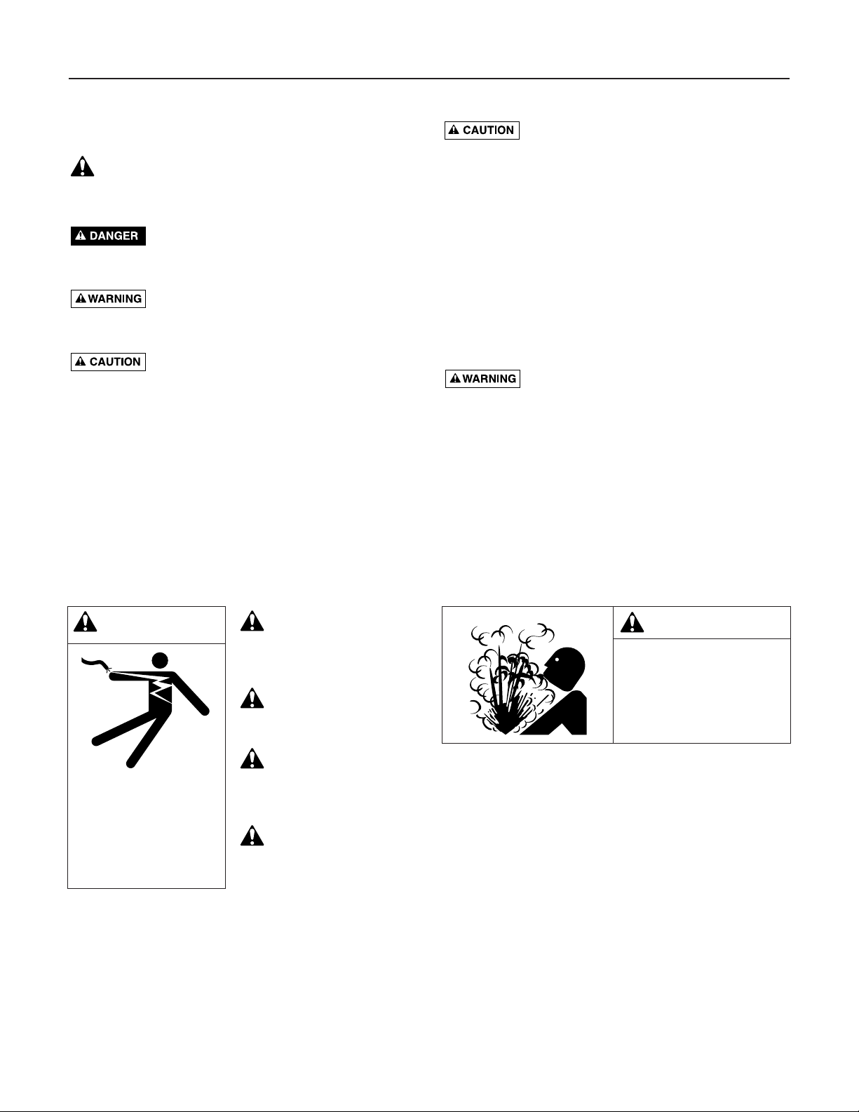
Figure 1
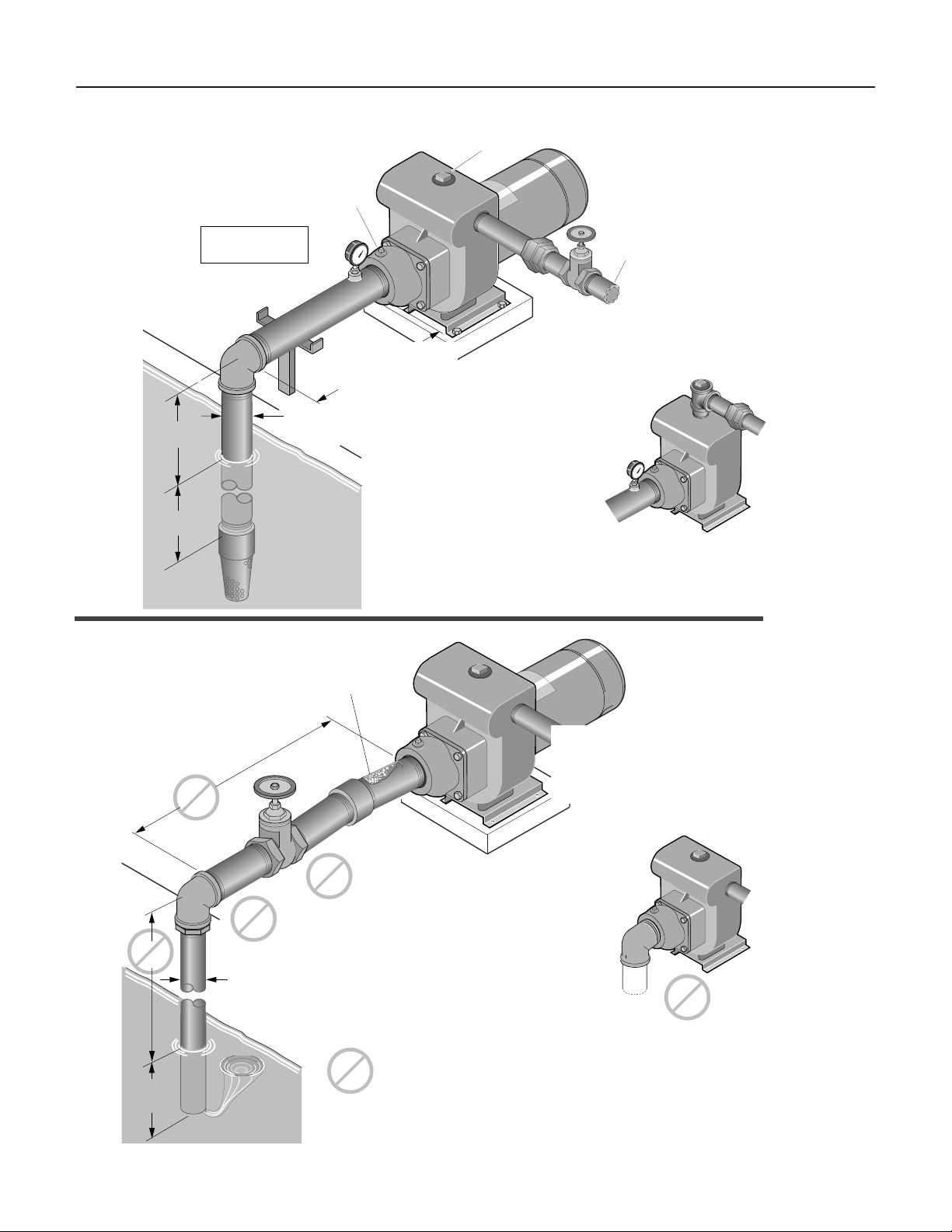
Figure 2
Priming
Plug
Offset suction flange adapter
keeps suction water level
above impeller eye to aid priming.
Important:
All connections must
be
air tight
Support suction pipe
as required
As close
as possible
4 x "D"
minimum
Misaligned pipe causes
high spots along the suction line
result in
Straight run, short as
possible but at least 6
times pipe diameter ("D");
slope is
from pump.
Pipe diameter "D"
at least as large as
pump suction connection
air leaks;
air pockets.
Discharge
to service
down
going away
Union
Solid, level
base
Gate
Valve
Support discharge
pipe as required
Some models have top
discharge; these require
a priming tee.
Recommended pump suction
and discharge connections
Long suction
run
High
lift
Pipe submerged
less than 4 x "D"
will cause vortexing
Unsupported
Pipe
Pipe diameter "D"
insufficient size
Use of excess fittings
means potential
Valve
On the discharge
Quick closing valves.
Small I.D. pipe.
Numerous fittings.
Misalignment.
Sharp turns in piping run.
air leaks
Not
recommended pump suction
and discharge connections
avoid:
Elbow immediately
in front of pump
suction.
1239 0894
Page 5

Installation 5
LOCATION OF UNIT
Locate the pump as near the liquid source as possible, using a short, direct
suction pipe. Keep the static suction lift (vertical distance between the center line of the pump and the liquid level) to a minimum. Mount the pump
on a solid, level foundation, which provides a rigid and vibration-free support. It should be located where the unit is readily accessible for service
and maintenance. The pump should be protected against flooding and
excessive moisture.
PIPING
Both suction and discharge piping should be independently supported at a
point near the pump to avoid strains being placed on the pump. Start all
piping at pump to avoid strains left by a gap at last connection.
SUCTION PIPING
The suction pipe must be kept free of leaks. The suction pipe must have a
gradual slope upward to the pump. Avoid any fittings which may cause an
air trap. On units that have a suction fitting, a check valve is a built-in feature and no foot valve is required.
DISCHARGE PIPING
A gate valve and union should be installed in the discharge line. For
removal of the pump for service, close the gate valve, and disconnect at
union.
Page 6

Electrical 6
Disconnect power at service panel before connecting motor.
Single phase motors come factory wired for 230 volt operation. Do not
alter wiring in single phase motors. Match motor voltage to power supply
voltage. Do not connect three phase motors to single phase power supply
or single phase motors to three phase power supply.
Ground motor before connecting to electrical power supply.
Failure to ground motor can cause severe or fatal electrical shock
hazard.
Do not ground to a gas supply line.
To avoid dangerous or fatal electrical shock, turn OFF power to
motor before working on electrical connections.
Supply voltage must be within ±10% of nameplate voltage. Incorrect
voltage can cause fire or seriously damage motor and voids warran-
ty. If in doubt consult a licensed electrician.
Use wire size specified in Wiring Chart. If possible, connect pump to
a separate branch circuit with no other appliances on it.
WIRING
Step 1. Install, ground, wire and maintain this pump in accordance with your
local electrical code and all other codes and ordinances that apply.
Consult your local building inspector for local code information.
Step 2. Ground the pump permanently using a wire of size and type speci-
fied by local or National Electrical Code.
Do not ground to a gas supply line.
Step 3. Connect ground wire first. Connect to ground first, then to green
grounding terminal provided (identified as GRD or ). Make
ground connection to this terminal. Do not connect motor to electrical power supply until unit is permanently grounded; otherwise
serious or fatal electrical shock hazard may be caused.
Step 4. For best ground connection, connect to a grounded lead in the ser-
vice panel or to a metal underground water pipe or well casing at
least 10 ft. long. If plastic pipe or insulated fittings are used, run
ground wire directly to the metal well casing or use ground electrode furnished by the power company.
WARNING
Hazardous voltage.
Can shock, burn, or
cause death.
Ground pump before
connecting to power
supply.
Page 7

Electrical 7
Before using pump, check your motor nameplate for voltage.
Your electric supply voltage and the stamped nameplate voltage must
agree. Motors stamped 200 volts only or 230 volts only, must be used with
that voltage only. Motors stamped with two voltages (for example 230/460
volts), may be used with either supply voltage. For these motors check connections against wiring diagram on motor nameplate and make any
changes necessary to agree with your supply voltage. If in doubt, call a
licensed electrician. Incorrect voltage will cause serious damage to the
motor.
Some models are equipped with three phase motors. Three phase motors
require magnetic starters.
To check motors for proper rotation: The shaft can be seen through the
motor - pump adapter bracket. A mark can be made on the shaft to make
it easier to notice rotation. Jog the motor (start it briefly) and note the rotation.
It should rotate clockwise when viewed from the motor-end. If rotation is not
clockwise, see motor nameplate for hookup information. BE SURE power is
off to the motor when working on electrical connections.
Motor normally operates at high temperature and will be too
hot to touch. Before handling pump or motor, stop motor and allow it to
cool for 20 minutes.
TABLE I – Recommended Wire and Fuse Sizes
DIAMETER IN FEET FROM MOTOR TO METER
BRANCH
0’ 51’ 101’ 201’ 301’ 401’
MAX. FUSE*
TO TO TO TO TO TO
MOTOR LOAD RATING
50’ 100’ 200’ 300’ 400’ 500’
HP PHASE VOLTS AMPS AMPS
WIRE SIZE
3 1 230 17.0 25 12 12 12 10 8 8
3 1 200 19.6 30 10 10 10 10 8 8
3 3 200 11.0 15 14 14 14 12 10 10
3 3 230 9.6 15 14 14 14 12 12 10
3 3 460 4.8 15 14 14 14 14 14 14
5 1 230 28.0 40 8 8 8 8 6 6
5 1 200 32.2 50 8 8 8 8 6 6
5 3 200 17.5 25 10 10 10 10 8 8
5 3 230 15.2 20 12 12 12 10 10 8
5 3 460 7.6 15 14 14 14 14 14 14
*A Fusetron is recommended instead of a fuse in any motor circuit.
IMPORTANT: BE SURE lead wire opening on end of motor is fully sealed
when conduit or a pressure switch is not used. Failure to seal it properly
will allow dirt, rain, bugs, etc. to enter back compartment of motor through
conduit opening and cause switch malfunction.
Page 8

Service 8
Never run pump dry. Running pump without water may
cause pump to overheat, damaging seal and possibly causing burns to persons handling pump. Fill pump with water before starting.
Never run pump against closed discharge. To do so can boil
water inside pump, causing hazardous pressure in unit, risk of explosion
and possibly scalding persons handling pump.
PRIMING THE PUMP
A tee installed in the discharge opening of the pump, and provided with a
priming plug at the top position, will enable you to fill the pump with liquid. Once filled and the priming plug replaced, the pump will prime. The
pump should prime itself time after time, as long as the built-in check valve
functions.
MAINTENANCE
Little or no maintenance to pump is required other than possible replacement of shaft seal after a reasonable period of operation (see Page 10).
Lubricate motor according to motor manufacturer’s in-structions. Periodic
greasing is required for most motors.
PUMP STORAGE
Drain pump to prevent freezing.
Keep motor dry and loosely covered. Do not wrap with plastic sheeting;
trapped moisture could cause corrosion or insulation deterioration.
NOTE: A good rust inhibitor in the liquid end of cast iron pumps is recommended to prevent excessive corrosion.
PUMP START-UP AFTER STORAGE
Replace all drain plugs and close all drain valves in system.
Be sure all connections are tightly sealed.
After initial check is made, fill pump according to “Priming the Pump,”
above.
SHAFT SEAL REPLACEMENT
IMPORTANT: The highly polished and lapped faces of the seal are easily
damaged. Follow instructions and handle the seal with care.
Be sure unit is grounded and power disconnected before
attempting any work on pump or motor.
Hazardous
voltage
Page 9

Figure 3
Service 9
REMOVAL OF OLD SEAL
Refer to Figure 3 for Mechanical Seal parts indentificaiton.
Step 1. Disconnect all power to pump.
Step 2. Close isolation valves to cut pump off from system.
Step 3. Drain pump; be sure to vent pump.
Step 4. Remove motor hold down bolts and bolts holding adapter/seal
plate (Key No. 6, Page 11) to pump body (Key No. 20). Slide
motor, adapter/ seal plate and impeller (Key No. 12) backward to
clear pump body.
Step 5. Remove impeller screw and washer from end of shaft and slide
impeller off of shaft.
Step 6. Unbolt adapter/seal plate from motor.
Step 7. Use two screwdrivers (Figure 4) or bearing puller to carefully sep-
arate motor from adapter/seal plate, bringing rotating half of seal
(Key No. 10) off with adapter/seal plate. Shaft sleeve (Key No. 2A)
may come off with seal.
Step 8. Use hammer, if necessary, to drive shaft sleeve out of seal. Clean
up shaft sleeve with emery paper if necessary.
Step 9. Place adapter/seal plate face down on bench and drive old sta-
tionary half of seal out of adapter/seal plate by carefully taping
with screwdriver and hammer (Figure 5).
Step 10. Use a wire brush to thoroughly clean adapter/seal plate cavity. Be
sure all dust and grime are out of seal cavity before installing new
seal.
Figure 5
Figure 4
Stationary
Seat
Rotating
Seal
Spring
Rotating Seat will come off
with adapter/sealplate.
If Gear Puller is used,
place jackscrew here.
1420 1294
1421 1294
Page 10

Service 10
INSTALLING NEW SEAL
Step 1. IMPORTANT: Seal faces are highly polished and lapped. Handle
with care. Any mar, nick or scratch on seal face will cause it to
leak. BE SURE to install with polished faces toward each other.
Step 2. Clean polished surface of ceramic seat with clean cloth.
Step 3. Wet O-Ring around ceramic seat with liquid soap.
Step 4. Press stationary (ceramic) half of seal into cavity firmly and squarely
with thumb pressure. If it does not seal properly, remove and place
face up on bench. Re-clean adapter/seal plate cavity. Seal should
now seat correctly.
Step 5. If seal does not seat after recleaning adapter/seal plate cavity, place
a cardboard washer over polished face of seal and carefully press
into place using a piece of 1” standard pipe as a press. (Figure 6).
NOTE: BE SURE you do not scratch seal face.
Step 6. Dispose of cardboard washer and recheck seal face to be sure it is
free of dirt, foreign particles, scratches and grease.
7. Inspect shaft and shaft sleeve to be sure they are clean.
8. Re-install O-Ring, shaft sleeve and slinger (Key No. 4) on shaft.
NOTE: A small amount of grease or Never-Seez under shaft sleeve
will help prevent shaft and sleeve from freezing together when
pump is in service.
9. Remount adapter/seal plate to motor, being careful not to scratch
seal face.
Step 10. Apply liquid soap to inside diameter and outside face of rubber
drive ring on rotating half of seal.
Step 11. Slide seal assembly onto shaft sleeve (sealing face first) far enough
so that seal spring is located on shaft sleeve. NOTE: Be careful not
to nick carbon seal face when passing it over end of shaft sleeve.
Step 12. Slide impeller and gaskets (Key Nos. 12 and 11) onto shaft with
key (Key No. 3) in position. Be sure to maintain proper order as
shown in Exploded View, Page 11.
Step 13. Install washer, gaskets, and impeller screw (Key Nos. 14, 15, 16,
17) on end of shaft and tighten screw until it is snug. This should
locate seal in place and bring seal faces together.
Step 14. Re-install motor, adapter and impeller assembly on volute, using
new gasket (Key No. 7).
Step 15. Re-install motor hold-down bolts.
Step 16. Check all bolts for tightness.
Step 17. Pumps below water level: Close drains; open isolation valves to
fill pump. Pumps above water level: Prime pump. Open isolation
valves if they were closed at disassembly.
Step 18. When pump is full, close air vents.
Step 19. Reconnect power to pump and system is ready for operation.
Figure 6
1" Standard Pipe
Stationary Seat
Cardboard
Washer
(Supplied with seal)
1422 1294
Page 11

1
3
4
5
6
7
8
9
10
11
12
13
14
15
16
17
18
19
20
21
22
21
2
2A
1362 1094
Repair Parts 11
3 HP 5 HP 3 HP 5 HP
DMH-171 DHH-169
DMH3-171 DMJ-172 DHH3-169 DHJ-170
DM2H-171 DMJ3-172 DH2H-112 DHJ3-170
Key Part No. DM2H3-110 DM2J-172 DH2H3-112 DH2J-113
No. Description Used DM2H3-171 DM2J3-172 DH2H3-169 DH2J3-170
1 Motor - 60 Cycle - 230V, Single Phase 1 C218-177 C218-180 C218-177 C218-180
1 Motor - 60 Cycle - 230/460V, Three Phase 1 C218-179 C218-182 C218-179 C218-182
1 Motor - 60 Cycle - 200V, Single Phase 1 C218-191 C218-192 C218-191 C218-192
1 Motor - 60 Cycle - 200V, Three Phase 1 C218-178 C218-181 C218-178 C218-181
2 O-Ring 1 U9-265 U9-265 U9-265 U9-265
2A Sleeve 1 C23-58 C23-58 C23-58 C23-58
3 Key - Square 1 U65-42A U65-42A U65-42A U65-42A
4 Water Slinger - Single Phase 1 C69-15 C69-15 C69-15 C69-15
4 Water Slinger - 230/460V, Three Phase 1 C69-16 C69-15 C69-16 C69-15
4 Water Slinger - 200 V, Three Phase 1 C69-15 C69-15 C69-15 C69-15
5 Capscrew - 3/8 - 16 x 7/8” Lg. 8 U30-73ZP U30-73ZP U30-73ZP U30-73ZP
6 Adapter 1 C2-66 C2-66 C2-66 C2-66
7 Gasket - Adapter 1 C20-46 C20-46 C20-46 C20-46
8 Lockwasher - 3/8” 4 U43-12ZP U43-12ZP U43-12ZP U43-12ZP
9 Capscrew - 3/8 - 16 x 7/8” Lg. 4 U30-73ZP U30-73ZP U30-73ZP U30-73ZP
10 Shaft Seal 1 U109-220 U109-220 U109-220 U109-220
11 Gasket - Seal 1 C20-101 C20-101 C20-101 C20-101
12 Impeller 1 C5-246 C5-247 C5-248 C5-249
13 Wear Ring 1 J23-5 C23-14 J23-5 J23-5
14 Gasket 1 C20-100 C20-100 C20-100 C20-100
15 Washer - Impeller 1 C43-45SS C43-45SS C43-45SS C43-45SS
16 Gasket 1 C43-46 C43-46 C43-46 C43-46
17 Screw - Impeller - 3/8 - 16 x 3/4” Lg. 1 U30-72SS U30-72SS U30-72SS U30-72SS
18 Volute Diffuser (w/Wear Ring, Key No. 13) 1 C101-126 C101-126B C101-132 C101-132
19 Diffuser Ring 1 C21-2 C21-2 C21-2 C21-2
20 Pump Body 1 C76-12 C76-12C C76-12B C76-12
21 Pipe Plug - 1/4” NPT 2 U78-941ZPV U78-941ZPV U78-941ZPV U78-941ZPV
22 Capscrew - 5/16 - 18 x 3/4” Lg. 4 U30-60ZP U30-60ZP U30-60ZP U30-60ZP
Page 12

Repair Parts 12
1238 0894
1
2
3
4
5
6
SUCTION FLANGE ASSEMBLY
Key Part No. Part
No. Description Used Symbol
1 Valve Plate 1 C61-5SS
2 Gasket - Flange 1 C20-15
3 Valve Washer 1 C43-15SS
4 Machine Screw 1/4-20 x 1/2” 1 U30-50SS
5 Pipe Plug - 1/4” NPT Sq. Hd. 1 U78-57SSS
6 Suction Flange 2” NPT 1 C3-22A
6 Suction Flange 2-1/2” NPT 1 C3-74
6 Suction Flange 3” NPT 1 C3-74B
• Nut, 1/4-20, Hex 1 BC120-15
Suction Flange Assembly-
Complete 1-1/2” NPT C203-22
Suction Flange Assembly-
Complete 2” NPT C203-22A
 Loading...