

Page 1
OWNER’S MANUAL
INSTALLATION AND OPERATING INSTRUCTIONS
REPAIR PARTS LIST
60 CYCLE
SELF-PRIMING CENTRIFUGAL PUMPS
“D” SERIES
MODELS
1 HP 1-1/2 HP 2 HP 2-1/2 HP
DMG-41L DMMG-42L
MEDIUM HEAD DMG3-41 DMMG3-42
DMM2G-42
DHE-50L DHF-51L DHG-52L DHHG-53L
HIGH HEAD DHE3-50 DHF3-51 DHG3-52 DHHG3-53
DH2E3-50
STA-RITE INDUSTRIES, DELAVAN, WISCONSIN 53115
©2005, Sta-Rite Industries S878 (Rev. 9/26/05)
LIMITED WARRANTY
Sta-Rite Industries warrants to the original consumer of the products listed below, that they will be free from defects in material and workmanship for
the Warranty Period from the date of original installation or manufacture as noted.
Product Warranty Period
Water Systems Products – jet pumps,
whichever occurs first:
small centrifugal pumps, submersible pumps 1 year from date of original installation, or
and related accessories 2 years from date of manufacture
Hydro-Flow Filters 1 year from date of purchase
Signature 2000 Fibrewound Tanks 5 years from date of original installa ion
Pro-Source Steel Pressure Tanks 5 years from date of original installation
Pro-Source Epoxy-Line Tanks 3 years from date of original installation
Sump/Sewage/Effluent Products 1 year from date of original installation, or
2 years from date of manufacture
Our warranty will not apply to any product hat has been subject to negligence, misapplication, improper installation or maintenance. In the event
a three phase submersible motor is operated with single phase power through a phase converter, or if three-leg ambient compensated, extra-quick
trip overload relays of recommended size are not used, our warranty is void.
Buyer’s only remedy and Sta-Rite Industries’ only duty is to repair or replace defective products (at Sta-Rite Industries’ choice). Buyer agrees to
pay all labor and shipping charges associated with this warranty and to request warranty service through the installing dealer as soon as a problem is discovered. If warranty service is requested more han 30 days after he Warranty Period has ended, it will not be honored.
STA-RITE INDUSTRIES SHALL NOT BE LIABLE FOR ANY CONSEQUENTIAL, INCIDENTAL, OR CONTINGENT DAMAGES WHATSOEVER.
THE FOREGOING WARRANTIES ARE EXCLUSIVE AND IN LIEU OF ALL OTHER EXPRESS WARRANTIES. IMPLIED WARRANTIES,
INCLUDING BUT NOT LIMITED TO THE IMPLIED WARRANTIES OF MERCHANTABILITY AND FITNESS FOR A PARTICULAR PURPOSE,
SHALL NOT EXTEND BEYOND THE WARRANTY PERIOD PROVIDED HEREIN.
Certain states do not permit he exclusion or limitation of incidental or consequential damages or the placing of limitations on the duration of an
implied warranty, therefore, the limitations or exclusions herein may not apply. This warranty sets forth specific legal rights and obligations, however, additional rights may exist, which may vary from state to state.
Supersedes all previous publications.
Sta-Rite Industries, Inc. 293 Wright St., Delavan, WI 53115
Page 2
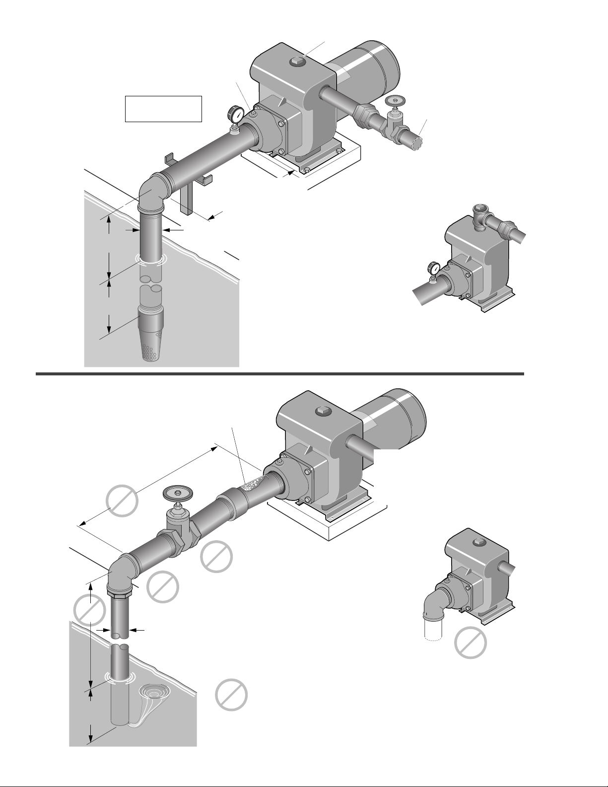
Support suction pipe
as required
Support discharge
pipe as required
As close
as possible
4 x "D"
minimum
Pipe diameter "D"
at least as large as
pump suction connection
Important:
All connections must
be
air tight
Solid, level
base
Priming
Plug
Gate
Valve
Union
Discharge
to service
Recommended pump suction
and discharge connections
Not
recommended pump suction
and discharge connections
Elbow immediately
in front of pump
suction.
High
lift
Pipe diameter "D"
insufficient size
Pipe submerged
less than 4 x "D"
will cause vortexing
Long suction
run
Valve
Unsupported
Pipe
Misaligned pipe causes
air leaks;
high spots along the suction line
result in
air pockets.
Offset suction flange adapter
keeps suction water level
above impeller eye to aid priming.
Use of excess fittings
means potential
air leaks
Straight run, short as
possible but at least 6
times pipe diameter ("D");
slope is
down
going away
from pump.
1239 0894
Some models have top
discharge; these require
a priming tee.
On the discharge
avoid:
Quick closing valves.
Small I.D. pipe.
Numerous fittings.
Misalignment.
Sharp turns in piping run.
Figure 1
Figure 2
2
Page 3
3
LOCATION OF UNIT
Locate the pump as near the liquid source as possible,
using a short, direct suction pipe. Keep the static suction lift (vertical distance between the center line of the
pump and the liquid level) to a minimum. Mount the
pump on a solid, level foundation, which provides a
rigid and vibration-free support. It should be located
where the unit is readily accessible for service and
maintenance. The pump should be protected against
flooding and excessive moisture. Do not allow pump or
any system component to freeze.
PIPING
Both suction and discharge piping should be independently supported at a point near the pump to avoid
strains being placed on the pump. Start all piping at
pump to avoid strains left by a gap at last connection.
SUCTION PIPING
The suction pipe must be kept free of leaks. The suction pipe must have a gradual slope upward to the
pump. Avoid any fittings which may cause an air trap.
On units that have a suction fitting, a check valve is a
built-in feature and no foot valve is required.
DISCHARGE PIPING
A gate valve and union should be installed in the discharge line. For removal of the pump for service, close
the gate valve, and disconnect at union.
Never run pump dry. Running pump
without water may cause pump to overheat, damaging
seal and possibly causing burns to persons handling
pump. Fill pump with water before starting.
Never run pump against closed discharge. To do so can boil water inside pump, caus-
ing hazardous pressure in unit, risk of explosion and
possibly scalding persons handling pump.
PRIMING THE PUMP
A tee installed in the discharge opening of the pump,
and provided with a priming plug at the top position, will
enable you to fill the pump with liquid. Once filled and
the priming plug replaced, the pump will prime. The
pump should prime itself time after time, as long as the
built-in check valve functions.
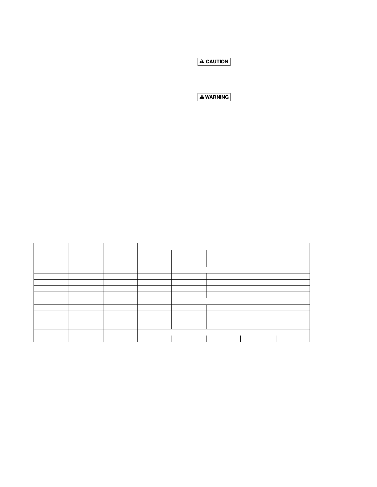
TABLE I - RECOMMENDED FUSING AND WIRING DATA - 60 CYCLE MOTORS
DIAMETER IN FEET FROM MOTOR TO METER
BRANCH 0’ 101’ 201’ 301’ 401’
FUSE* TO TO TO TO TO
MOTOR MAX. LOAD RATING 100’ 200’ 300’ 400’ 500’
HP AMPERES AMPS
115/230 VOLT SINGLE PHASE WIRE SIZE
1 15.3/7.6 20/15 12/14 8/14 6/14 6/12 4/10
1-1/2 19.2/9.6 25/15 10/14 8/14 6/12 4/10 4/10
2 24.0/12.0 30/15 10/14 6/14 6/12 4/10 4/10
2-1/2 26.0/12.0 30/15 10/14 16/14 4/12 4/10 4/10
230/460 VOLT THREE PHASE WIRE SIZE
1 3.6/1.8 15/15 14/14 14/14 14/14 14/14 14/14
1-1/2 4.7/2.35 15/15 14/14 14/14 14/14 14/14 14/14
2 6.8/3.4 15/15 14/14 14/14 14/14 12/14 12/14
2-1/2 8.5/4.25 15/15 14/14 14/14 14/14 12/14 10/14
200/400 VOLT THREE PHASE WIRE SIZE
1 3.8/1.9 15/15 14/14 14/14 14/14 14/14 14/14
*A Fusetron is recommended instead of a fuse in any motor circuit.
IMPORTANT: BE SURE lead wire opening on end of
motor is fully sealed when conduit or a pressure switch
is not used. Failure to seal it properly will allow dirt, rain,
bugs, etc. to enter back compartment of motor through
conduit opening and cause switch malfunction.
Page 4

4
Connection diagram for dual voltage, single-phase
motors. Your dual-voltage motor’s terminal board
(under the motor end cover) will match one of the
diagrams below. Follow that diagram if necesary to
convert motor to 115 Volt power.
Connect power supply wires to L1 and L2. For
3-phase motors, or if motor does not match these
pictures, follow the connection diagram on the motor
nameplate.
THE MOTOR IS SET FOR 230 VOLTS
WHEN SHIPPED.
To change the motor to use 115 volts:
1. Turn off power
2. Remove the back motor cover.
3. Use a screwdriver or 1/2” wrench and turn the voltage selector dial counterclockwise until 115 shows in
the dial opening.
4. Reinstall the motor cover.
Hazardous voltage. Can shock, burn, or
cause death. Disconnect power to motor before working
on pump or motor. Ground motor before connecting to
power supply.
WIRING
Ground motor before connecting to electrical
power supply. Failure to ground motor can
cause severe or fatal electrical shock hazard.
Do not ground to a gas supply line.
To avoid dangerous or fatal electrical shock,
turn OFF power to motor before working on
electrical connections.
Supply voltage must be within ±10% of name-
plate voltage. Incorrect voltage can cause fire
or damage motor and voids warranty. If in doubt
consult a licensed electrician.
Use wire size specified in Wiring Chart (Page
3). If possible, connect pump to a separate
branch circuit with no other appliances on it.
Wire motor according to diagram on motor
nameplate. If nameplate diagram differs from
diagrams above, follow nameplate diagram.
1. Install, ground, wire and maintain this pump in accor-
dance with electrical code requirements. Consult your
local building inspector for information about codes.
2. Provide a correctly fused disconnect switch for pro-
tection while working on motor. Consult local or
national electrical codes for switch requirements.
3. Disconnect power before servicing motor or pump. If the
disconnect switch is out of sight of pump, lock it open
and tag it to prevent unexpected power application.
4. Ground the pump permanently using a wire of the
same size as that specified in wiring chart (Page 3).
Make ground connection to green grounding terminal
under motor canopy marked GRD. or .
5. Connect ground wire to a grounded lead in the ser-
vice panel or to a metal underground water pipe or
well casing at least 10 feet long. Do not connect to
plastic pipe or insulated fittings.
6. Protect current carrying and grounding conductors
from cuts, grease, heat, oil, and chemicals.
7. Connect current carrying conductors to terminals L1 and
L2 under motor canopy. When replacing motor, check
wiring diagram on motor nameplate against Figure 3. If
the motor wiring diagram does not match either diagram
in Figure 3, follow the diagram on the motor.
IMPORTANT: 115/230 Volt single phase models are
shipped from factory with motor wired for 230 volts. If
power supply is 115 volts, remove motor canopy and
reconnect motor as shown in Figure 3. Do not try to run
motor as received on 115 volt current.
8. Motor has automatic internal thermal overload pro-
tection. If motor has stopped for unknown reasons,
thermal overload may restart it unexpectedly, which
could cause injury or property damage. Disconnect
power before servicing motor.
9. If this procedure or the wiring diagrams are confus-
ing, consult a licensed electrician.
ELECTRICAL
Motor Terminal Block Wiring (as viewed from rear of motor, canopy removed)
Figure 3: Changing the Voltage Setting
Figure 4: Motor Set for 115 Volt Operation
Page 5

5
PUMP SERVICE
This centrifugal pump requires little or no service other
than reasonable care and periodic cleaning. Occasionally, however, a shaft seal may become damaged and
must be replaced. The procedure as outlined below will
enable you to replace the seal.
NOTE: Pumps use mechanical seals with a rubber
seat ring or a sealing O-Ring. THESE SEALS ARE
COMPLETELY INTERCHANGEABLE.
NOTE: The highly polished and lapped faces of this
seal are easily damaged. Read instructions and handle
the seal with care.
Some models are equipped with an impeller screw,
which has a left hand thread. Before unscrewing the
impeller, remove the impeller screw.
REMOVAL OF OLD SEAL
1. After unscrewing impeller, carefully remove rotating
part of seal by prying up on sealing washer, using
two screwdrivers (see Figure 5A). Use care not to
scratch motor shaft.
2. Remove seal plate from motor and place on flat surface, face down. Use a screwdriver to push ceramic
seat out from seal cavity (see Figure 5B).
INSTALLATION OF STATIONARY SEAT (Figure 5C)
1. Clean polished surface of stationary seat with clean
cloth.
2. Turn seal plate over so seal cavity is up, clean cavity thoroughly.
3. Lubricate outside rubber surface of ceramic seat
with soapy water and press firmly into seal cavity
with finger pressure. If seat will not locate properly in
this manner, place cardboard washer over polished
face of seat and press into seal cavity using a 3/4”
socket or 3/4” piece of standard pipe.
4. DISPOSE OF CARDBOARD WASHER. Be sure
polished surface of seat is free of dirt and has not
been damaged by insertion. Remove excess soapy
water.
INSTALLATION OF ROTATING
PART OF SEAL UNIT (Figure 5D)
1. Reinstall seal plate using extreme caution not to hit
ceramic portion of seal on motor shaft.
2. Inspect shaft to make sure that it is clean.
3. Clean face of sealing washer with clean cloth.
4. Lubricate inside diameter and outer face of rubber
drive ring with soapy water and slide assembly on
motor shaft (sealing face first) until rubber drive ring
hits shaft shoulder.
5. Screw impeller on shaft until impeller hub hits shaft
shoulder. This will automatically locate seal in place
and move the sealing washer face up against seat
facing. Reinstall impeller screw (if used).
MAINTENANCE
Be sure to drain pump during freezing weather to prevent damage from frost. To drain, remove drain plugs
directly below the suction inlet of the pump. Drain the
suction pipe to a point below the frost line. All other
pipes that may be exposed to freezing temperatures
should also be drained.
FIGURE 5
SERVICE
685 0294
Mechanical seal
Mechanical seal
rotating half
A-Seal removal-rotating half B-Seal removal-stationary half C-Stationary half installation D-Rotating half installation
stationary half
Seal Plate
T
3/4" socket
or pipe
Cardboard
washer
Polished
surface
o
n
v
r
e
u
r
(supplied w/seal)
Rubber
surface
Sealing
face
Shaft
shoulder
Rubber drive
ring
Impeller
Page 6

6
“D” SERIES REPAIR PARTS LIST
60 CYCLE 1 and 1-1/2 HP HIGH HEAD; 2 and 2-1/2 HP MEDIUM HEAD
1 HP 1-1/2 HP 2 HP 2-1/2 HP
DHE-50L DHF-51L DMG-41L DMMG-42L
Key Part No. DHE3-50 DHF3-51 DMG3-41 DMMG3-42
No. Description Used DH2E3-50 DMM2G-42
1 Motor - 115/230V/60 Hz/1 Ph 1 A100ELL A100FLL – –
1 Motor - 230V/60 Hz/1 Ph 1 – – AE100GLL AE100G5LL
1 Motor - 230/460V/60 Hz/3 Ph 1 AP100EL AP100FL AP100GL AP100G5L
1 Motor - 200/400V/60 Hz/3 Ph 1 AP100ELL – – AP100G5L2
2 3/8 - 16 x 1-1/4” Cap Screw 4 U30-75ZP U30-75ZP U30-75ZP U30-75ZP
3 Water Slinger 1 17351-0009 17351-0009 17351-0009 17351-0009
4A Seal Plate 1 – – C3-23 C3-23
4B Seal Plate 1 C3-52 C3-52 – –
5 Seal Plate Gasket 1 C20-21 C20-21 C20-21 C20-21
6 Shaft Seal 1 U109-6A U109-6A U109-6A U109-6A
7A Impeller - (1 Phase) 1 C105-92PLC C105-92PB C105-114PNA C105-80EA
7A Impeller - (3 Phase) 1 C105-92PLA C105-92PBA C105-114PNA C105-80EA
7B Impeller Screw 1 C30-14SS* C30-14SS* C30-14SS C30-14SS
8 Wear Ring 1 C23-27 C23-27 C23-32D C23-32D
9A Diffuser (Includes Key No. 8) 1 – – C101-56C C101-72
9B Diffuser (Includes Key No. 8) 1 C101-212B C101-212B – –
10 Diffuser Ring 1 C21-2 C21-2 C21-2 C21-2
11 1/4 NPT Pipe Plug 3 U78-941ZPV U78-941ZPV U78-941ZPV U78-941ZPV
12A Pump Body 1 C76-1J C76-1J C76-1J C76-1L
12B 1-1/2 NPT Pipe Plug 1 U78-63GPS U78-63GPS U78-63GPS U78-63GPS
13 5/16 - 18 x 3/4” Cap Screw 4 U30-60ZP U30-60ZP U30-60ZP U30-60ZP
14 Base 1 U4-5 U4-5 U4-5 U4-5
15 3/8” Lock Washer 2 U43-12ZP U43-12ZP U43-12ZP U43-12ZP
16 3/8 - 16 x 5/8” Cap Screw 2 U30-71ZP U30-71ZP U30-71ZP U30-71ZP
*3 Phase only.
1
2
3
4B
4A
5
6
7A
8
9A
9B
10
11
12A
12B
11
13
11
14
15
16
1443 1294
7B
Page 7

7
“D” SERIES REPAIR PARTS LIST
60 CYCLE 2 and 2-1/2 HP HIGH HEAD
2 HP 2-1/2 HP
Key Part No. DHG-52L DHHG-53L
No. Description Used DHG3-52 DHHG3-53
1 Motor - 230V/60 Hz/1 Ph 1 AE100GLL AE100G5LL
1 Motor - 230/460V/60 Hz/3 Ph 1 AP100GL AP100G5L
2 3/8 - 16 x 1” Cap Screw 4 U30-74ZP U30-74ZP
3 Water Slinger 1 17351-0009 17351-0009
4 3/8 - 16 x 3/4” Cap Screw 8 U30-72ZP U30-72ZP
5 Seal Plate 1 C103-35 C103-35
6 Seal Plate Gasket 1 C20-46 C20-46
7 Shaft Seal 1 U109-6A U109-6A
8A Impeller 1 C105-214PCA C105-214PA
8B Impeller Screw 1 C30-14SS C30-14SS
9 Wear Ring 1 C23-19 C23-19
10 Diffuser (Includes Key No. 9) 1 C101-77 C101-77
11 Diffuser Ring 1 C21-2 C21-2
12 Pump Body 1 C76-12 C76-12
13 1/4 NPT Drain Plug 2 U78-941ZPV U78-941ZPV
14 5/16 - 18 x 3/4” Cap Screw 4 U30-60ZP U30-60ZP
15 Base 1 U4-5 U4-5
16 3/8” Lock Washer 2 U43-12ZP U43-12ZP
17 3/8 - 16 x 5/8” Cap Screw 2 U30-71ZP U30-71ZP
1
2
3
4
5
6
7
8A
9
10
11
13
15
8B
17
16
1442 1294
12
13
14
Page 8

8
TROUBLE - CAUSES AND REMEDY
TROUBLE AND CAUSE REMEDY
FAILURE TO PUMP
1. Pump not properly primed. 1. Make sure pump casing and suction line are full of water.
See priming instructions.
REDUCED CAPACITY AND/OR HEAD
1. Air pockets or leaks in suction line. 1. Check suction piping.
2. Clogged impeller. 2. Remove and clean.
PUMP LOSES PRIME
1. Air leaks in suction line. 1. Check suction piping
2. Excessive suction lift and operating 2. Move pump nearer to water level.
too near shut-off point.
3. Water level drops while pumping, 3. Check water supply. Add length of pipe to suction
uncovering suction piping. to keep submerged end under water.
MECHANICAL TROUBLES AND NOISE
1. Bent shaft and/or damaged bearings. 1. Take motor to authorized motor repair shop.
2. Suction and/or discharge piping not 2. See that all piping is supported to relieve strain
properly supported and anchored. on pump assembly.
1238 0894
1
2
3
4
5
6
Key Part No. Part
No. Description Used Symbol
1 Valve Plate 1 C61-5SS
2 Gasket - Flange 1 C20-15
3 Valve Washer 1 C43-15SS
4 Machine Screw 1/4-20 x 1/2” 1 U30-50SS
5 Pipe Plug - 1/4” NPT Sq. Hd. 1 U78-57SSS
6 Suction Flange 1-1/2” NPT 1 C3-22
6 Suction Flange 2” NPT 1 C3-22A
• Nut, 1/4-20, Hex 1 BC120-15
Suction Flange Assembly-
Complete 1-1/2” NPT C203-22
Suction Flange Assembly-
Complete 2” NPT C203-22A
Suction Flange Assemblies
 Loading...