

STA-RITE CRISTAL-FLO, CRISTAL-FLO T-150BP-1, CRISTAL-FLO T-170BP-1, CRISTAL-FLO T-200BP-1, CRISTAL-FLO T-240BP-1 Owner's Manual
...
CRISTAL-FLO
TM
HIGH RATE SAND FILTERS
O W N E R’ SMA N U A L
INSTALLATION, OPERATION & PARTS
MODELS
T-150BP-1 T-170BP-1 T-200BP-1 T-240BP-1 T-300BP-2
Sta-Rite Pool/Spa Group
293 Wright Street, Delavan, WI 53115
International: 262-728-5551, FAX: 262-728-7550
www.starite.com
Union City, TN • Delavan, WI • Mississauga, ON
© 2005, Sta-Rite Industries
S242 (Rev. C 12/17/07)
This manual should be furnished to
the end user of this filter; its use will
reduce service calls and chance of
injury and will lengthen filter life.
R
E
CIR
C
U
L
A
T
E
B
A
C
K
W
A
S
H
E
W
A
S
T
E
F
ILT
E
R
Aquatools
.WATERFORD, WI.
53185
USA
729 0294
Pentair Pool Products, Inc.
1620 Hawkins Ave.
Sanford, NC 27330
Tel 919-774-4151 • F
ax 919-774-4841
S242 (Rev. C 12/17/07)
HIGH RATE SAND FILTERS
o avoid unneeded service calls, prevent possible injuries, and get the most
T
ut of your filter, READ THIS MANUAL CAREFULLY!
o
The Sta-Rite Top Mounted Series High Rate Sand Filter:
• Is designed to filter water for swimming pools.
• Is an excellent performer; durable, reliable.
Table of Contents
Safety Instructions .....................................................................................2-3
Dimensions/Specifications ............................................................................4
General Information .....................................................................................5
Installation ................................................................................................5-7
Filter Mount/Piping....................................................................................5
Filter Set-up...............................................................................................6
Loading Sand Media..................................................................................6
Valve Installation .......................................................................................6
Startup/Operation ......................................................................................7
Maintenance ................................................................................................8
Water Maintenance ...................................................................................8
Storage/Winterizing .................................................................................8-10
Mult-Port Valve Service .............................................................................9
Drain Fitting Installation/Removal ............................................................10
Troubleshooting Guide................................................................................11
Repair Parts List.....................................................................................12-13
Pressure Drop Curve...................................................................................14
Warranty ....................................................................................................15
READ AND FOLLOW SAFETY
INSTRUCTIONS!
This is the safety-alert symbol. When you see this symbol on your valve
or in this manual, look for one of the following signal words and be alert to the
potential for personal injury.
warns about hazards that will cause serious personal injury,
death or major property damage if ignored.
warns about hazards that can cause serious personal injury,
death or major property damage if ignored.
warns about hazards that will or can cause minor personal in-
jury or property damage if ignored.
The label NOTICE indicates special instructions which are important but not
related to hazards.
Carefully read and follow all safety instructions in this manual and on filter.
Keep safety labels in good condition.
Replace missing or damaged safety labels.
2
Incorrectly installed or tested equipment may fail, causing severe injury or property damage. Read and follow instructions
n owner's manual when installing and operating equipment.
i
ave a trained pool professional perform all pressure tests.
H
1. Do not connect system to a high pressure or city water system.
2. Use equipment only in a swimming pool installation.
3. Trapped air in system can cause explosion. BE SURE all air is out of system
before operating or testing equipment.
Before pressure testing, make the following safety checks:
• Check all clamps, bolts, lids, and system accessories before testing.
• BE SURE all air is out of system before testing.
• Tighten Sta-Rite trap lids to 30 ft. lbs. (4.1 kg-cm) torque for testing.
• Water pressure for test must be less than 25 PSI (172 kPa).
• Water temperature for test must be less than 95˚ F. (35˚ C).
• Limit test to 24 hours. After test, visually check system to be sure it is ready
for operation. Remove trap lid and retighten hand tight only.
NOTICE: These parameters apply to Sta-Rite equipment only. For
non-Sta-Rite equipment, consult manufacturer.
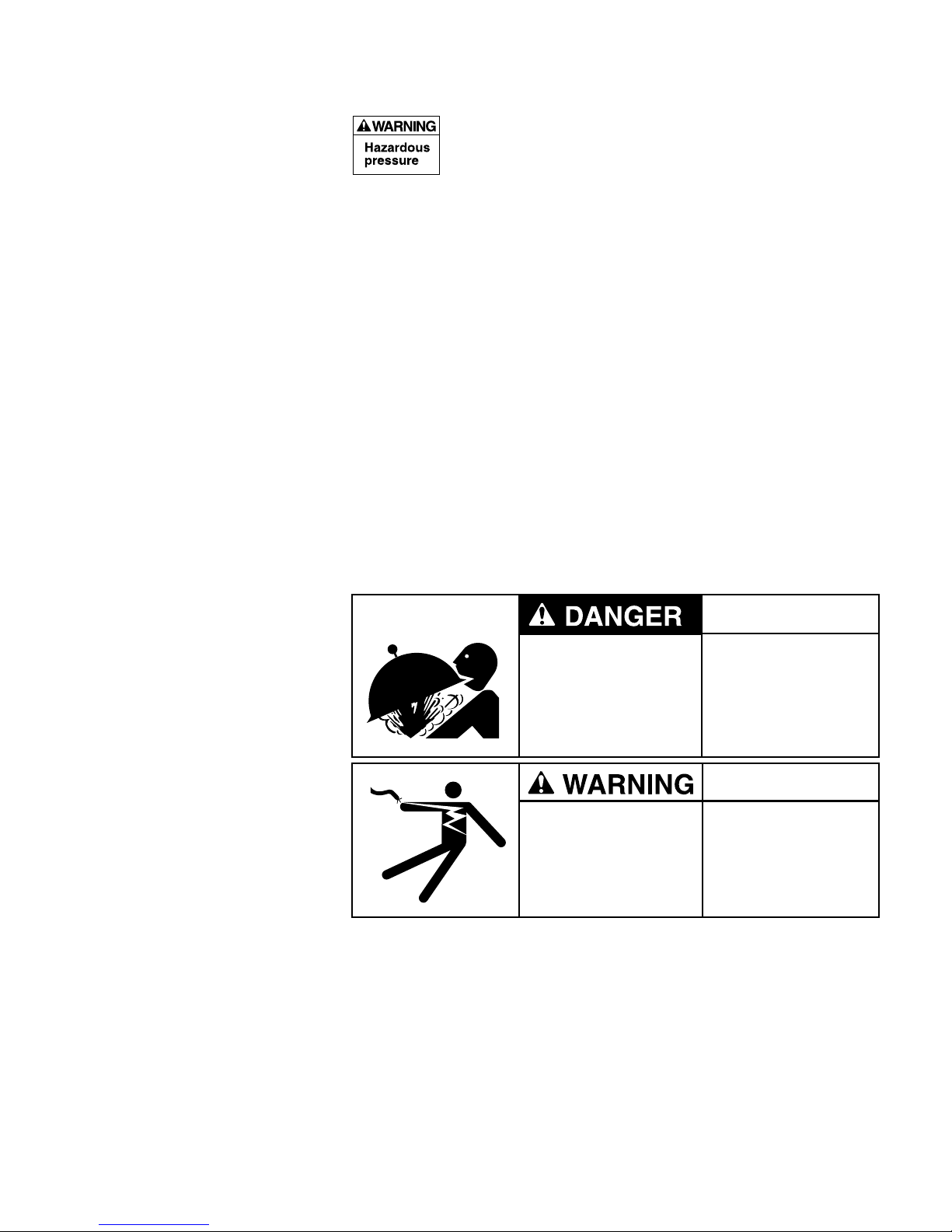
Hazardous Pressure!
Can cause severe
injury or major
property damage from
tank explosion.
Filter pumps require
hazardous voltage
which can shock, burn,
or cause death.
BEFORE WORKING
ON FILTER:
1. Stop pump.
2. Open air release
valve.
3. Release all pressure
from system.
BEFORE WORKING
ON PUMP OR MOTOR
Disconnect power to
motor.
3
Waste Outlet 1-1/2"
P
ump Inlet 1-1/2"
Return Outlet
1-1/2" Slip
C
Dia.
Union connection
.88 (73)
2
D
355 1094
E,F
1
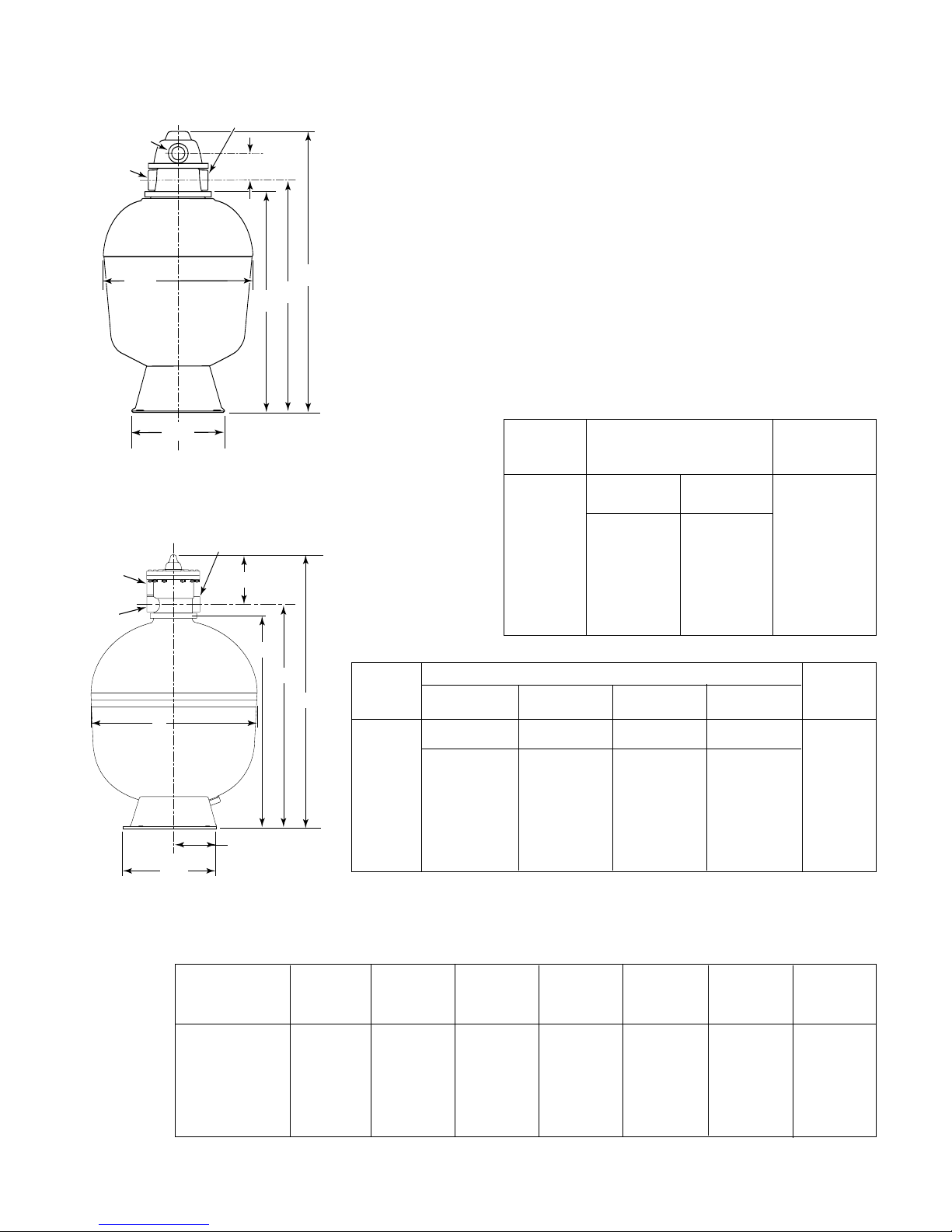
Fig. 1: Dimensions, T-150BP-1,
T-170BP-1 T-200BP-1, T240BP-1
2" NPT Outlet
(
Waste)
2
" NPT Inlet
(Pump)
2" NPT
Outlet
(Return)
C
9.25 (235)
D
See Page 14 for Pressure Drop Curve.
RECOMMENDED SAND GRADES:
se only: #20 Silica Sand, Size Range .40-.55mm., Uniformity Coefficient less
U
han 1.75.
t
NOTICE: Use of other sands will reduce filter performance, may damage
pump, and will void warranty.
B
A
Recommended:
1. Wedron Silica/Best Sand Co., Sand Grade: Wedron .45-.55mm., Effective
Size .46mm, Uniformity Coefficient 1.22.
2. U.S. Silica - Silurian Filter Sand, Sand Grade.45-.55 mm., Effective Size
.48mm, Uniformity Coefficient 1.18.
TABLE I - FILTER OPERATIONAL DATA
Max.
Filter Filter Flow Rate
Model Size in GPM (L/M)
Dia. in Area in Ft
Inches (mm) (M2)
T-150BP-1 15 (381) 1.26 (.117) 25.2 (95)
T-170BP-1 17 (432) 1.57 (.146) 31.5 (123)
T-200BP-1 20 (508) 2.18 (.203) 43.6 (165)
T-240BP-1 24 (610) 3.10 (.288) 62.0 (234.7)
T-240BP-2 24 (610) 3.10 (.288) 62.0 (234.7)
T-300BP-2 30 (762) 4.90 (.455) 98 (371)
A
B
Filter Volume
Model 6 8 10 12 in lbs. (kg.)
Turnover in Hours Sand
gal. (L) gal. (L) gal. (L) gal. (L)
2
8.00(203)
E,F
1356 1094
Fig. 2: Dimensions, T-300BP-2,
T240BP-2
Filter Model No.
T-150BP-1 27 (686) 33-13/16 (859) 15-3/4 (400) 24-11/16 (627) 13 (330) 16-1/4 (413) 1-1/2” SLIP
T-170BP-1 29-9/16 (751) 36-3/8 (924) 17-3/4 (451) 27-1/4 (692) 13 (330) 16-1/4 (413) 1-1/2” SLIP
T-200BP-1 31-5/8 (803) 38-1/2 (978) 20-3/4 (527) 29-3/8 (746) 13 (330) 16-1/4 (413) 1-1/2” SLIP
T-240BP-1 35-3/16 (897) 42 (1067) 24-3/4 (629) 32-7/8 (835) 16-7/8 (429) 21 (533) 1-1/2” SLIP
T-240BP-2 35-1/4 (895) 44-1/2 (1130) 24-3/4 (629) 32-7/8 (835) 16-7/8 (429) 21 (533) 2” (NPT)
T-300BP-2 42 (1067) 51-1/4 (1302) 31 (787) 39-5/8 (1008) 16-7/8 (429) 21 (533) 2” (NPT)
T-150BP-1 9,070(34 330) 12,100(45 799) 15,120(57 229) 18,144(68 675) 100 (45.4)
T-170BP-1 11,340(42 922) 15,120(57 229) 18,900(71 536) 22,680(85 844) 150 (68)
T-200BP-1 15,700(59 424) 20,930(79 220) 26,160(99 016) 31,390(118 811) 200 (90.7)
T-240BP-1 22,230(84 481) 29,760(112 642) 37,200(140 802) 44,640(168 962) 300 (136)
T-240BP-2 22,230(84 481) 29,760(112 642) 37,200(140 802) 44,640(168 962) 300 (136)
T-300BP-2 35,280(133 535) 47,040(178 046) 58,800(222 558) 70,560(267 070) 600 (272)
*NOTE: 1 cubic foot of sand weighs approx. 100 lbs. (45.4 kg). Do not use finer or
coarser grade than recommended for best performance.
TABLE II - DIMENSIONAL DATA In Inches (mm)
Base Base Piping
Width Length Port
A B C D (E) (F) Size
4

5
GENERAL INFORMATION
•Clean a new pool as well as possible before filling pool and operating filter.
Excess dirt and large particles of foreign matter in the system can cause serious
damage to the filter and pump.
NEVER test this filter with compressed air.
Do not operate filter at water temperatures above 95°F (35°C).
NEVER operate this filter system at more than the stated pressure
on the filter tank.
INSTALLATION
Installation of filter should only be done by qualified, licensed personnel.
For assembly and filling instructions, see page 6.
Filter mount must:
• Provide weather and freezing protection.
• Provide space and lighting for easy access for routine maintenance. (See
Figures 1 and 2, Table II, Page 4, for space requirements.)
• Be on a reasonably level surface and provide adequate drainage.
•
Be as close to pool as possible to reduce line loss from pipe friction.
Piping:
•
Piping must conform to local/state plumbing and sanitary codes.
• Use pipe joint sealing compound or teflon tape on all male connections of
metal pipe and fittings (except unions). Use teflon tape or Plasto-Joint Stik
1
on
all male connections of plastic pipe and fittings. DO NOT use pipe dope on
plastic pipe; it will cause the pipe to crack. Do not use sealant or tape on
unions – assemble them dry and hand tight.
• Do not damage union sealing surfaces and “O” Rings.
•
Support pipe independently to prevent strains on filter or valve.
• Use 1-1/2 or 2” pipe to reduce pressure losses as much as possible.
NOTICE: Filter may be located away from pool, but for adequate flow larger
pipe may be needed. Check local codes when considering remote installation.
•
Fittings restrict flow; for best efficiency use fewest possible fittings
.
• Keep piping tight and free of leaks: pump suction line leaks may cause trapped
air in filter tank or loss of prime at pump; pump discharge line leaks may show
up as dampness or jets of water.
• When unions are provided, use as follows for leak free connections:
1. O-Ring and sealing surfaces must be clean.
2. Assemble hand tight only (no wrenches).
3. No pipe compound or teflon tape on unions.
Valves:
• A check valve installed between filter and heater will prevent hot water from
backing up into filter and deforming internal components.
• Use care before assembly not to damage union sealing surfaces or O Ring.
Wastewater:
• Be sure all provisions for waste water disposal meet applicable local, state or
national codes. 100 gallons (379 liters) or more of pool water will be discharged during filter backwashing. Do not discharge where water will cause
flooding or damage.
1
Lake Chemical Co., Chicago, IL
 Loading...