

Page 1
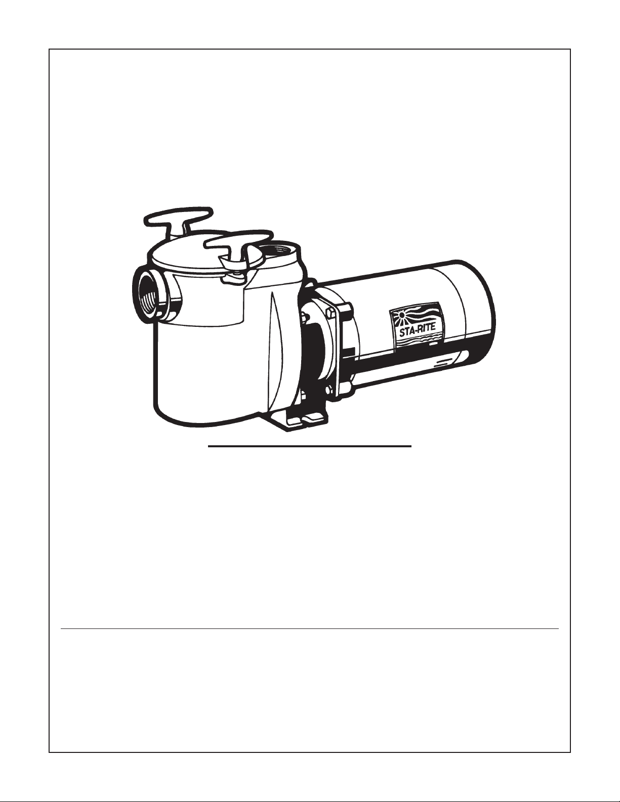
“CF6” SERIES BRONZE PUMP
WITH 6" INTEGRAL TRAP
SELF-PRIMING
O W N E R’ S M A N U A L
INSTALLATION, OPERATION & PARTS
MODELS
1-1/2 HP 2 HP 3 HP 3 HP
CF6EF-81L CF6EG-82L CF6H-123 CF6H3-123
1Ø 1Ø 1Ø CF6H3-123SA
1113Ø
Pentair Water Pool and Spa, Inc.
© 2009 Pentair Water Pool and Spa, Inc. All rights reserved.
1620 Hawkins Ave., Sanford, NC 27330 • (919) 566-8000
10951 West Los Angeles Ave., Moorpark, CA 93021 • (805) 553-5000
Sta-Rite® and Pentair Water Pool and Spa® are registered trademarks of Pentair Water Pool and Spa, Inc.and/or its affiliated companies in
the United States and/or other countries. Unless noted, names and brands of others that may be used in this document are not used to indicate an affiliation or endorsement between the proprietors of these names and brands and Pentair Water Pool and Spa, Inc. Those names
and brands may be the trademarks or registered trademarks of those parties or others.
Printed in U.S.A.
11/25/2009 S948 (Rev. A)
This manual must be given to the owner/user of this pump
Page 2
2
‘CF6’ SERIES PUMP WITH TRAP
To avoid unneeded service calls, prevent possible injuries,
and get the most out of your pump, READ THIS MANUAL
CAREFULLY!
The Sta-Rite ‘CF6’ Series Self-Priming Centrifugal Pump:
• Is designed for use with swimming pools or as a
centrifugal pump.
• Is an excellent performer; durable, reliable.
Table of Contents
Safety Instructions ........................................................2
Installation.................................................................3-4
Electrical ...................................................................4-5
Operation.....................................................................6
Storage/Winterizing ...................................................6-7
Pump Service ............................................................7-8
Troubleshooting Guide .................................................9
Repair Parts List ..........................................................10
Warranty ....................................................................12
Technical Support
Sanford, North Carolina
(8 A.M. to 5 P.M. EST)
Moorpark, California
(8 A.M. to 5 P.M. PST)
Phone: (800) 831-7133
Fax: (800) 284-4151
www.pentairpool.com www.staritepool.com
READ AND FOLLOW SAFETY
INSTRUCTIONS!
This is the safety alert symbol. When you see this
symbol on your system or in this manual, look for one
of the following signal words and be alert to the potential
for personal injury.
warns about hazards that will cause death,
serious personal injury, or major property damage if ignored.
warns about hazards that can cause death,
serious personal injury, or major property damage if ignored.
warns about hazards that will or can cause
minor personal injury or property damage if ignored.
NOTICE indicates special instructions not related to hazards.
Carefully read and follow all safety instructions in this
manual and on equipment. Keep safety labels in good
condition; replace if missing or damaged.
Incorrectly installed or tested equipment
may fail, causing severe injury or property
damage.
Read and follow instructions in owner's manual when
installing and operating equipment. Have a trained pool
professional perform all pressure tests.
1. Do not connect system to a high pressure or city water
system.
2. Use equipment only in a pool or spa installation.
3. Trapped air in system can cause explosion. BE SURE
all air is out of system before operating or testing
equipment.
Before pressure testing, make the following safety checks:
Check all clamps, bolts, lids, and system accessories before
testing.
Release all air in system before testing.
Tighten Sta-Rite trap lids to 30 ft. lbs. (4.1 kg-m) torque for
testing.
Water pressure for test must be less than 25 PSI (7.5 kg/cm
2
).
Water Temperature for test must be less than 100° F. (38° C).
Limit test to 24 hours. After test, visually check system to be
sure it is ready for operation. Remove trap lid and retighten
hand tight only.
NOTICE: These parameters apply to Sta-Rite equipment
only. For non-Sta-Rite equipment, consult manufacturer.
IMPORTANT
SAFETY INSTRUCTIONS
Always follow basic safety precautions with this
equipment, including the following.
To reduce the risk of injury, do not permit children to use this product unless they are closely
supervised at all times.
This pump is for use with permanently
installed pools and may also be used with hot tubs and
spas if so marked. Do not use with storable pools. A
permanently installed pool is constructed in or on the
ground or in a building such that it cannot be readily
disassembled for storage. A storable pool is constructed so that it may be readily disassembled for storage and reassembled to its original integrity.
SAVE THESE INSTRUCTIONS
Page 3

3
INSTALLATION
Only qualified, licensed personnel should install pump and
wiring.
Pump mount must:
Be located away from corrosive or flammable liquids.
Have enough ventilation to maintain air temperature at less
than the maximum ambient temperature rating (Max. Amb.)
listed on the motor model plate. If this pump is installed in
an enclosure/pump house, the enclosure must have
adequate ventilation and air circulation to keep the
temperature in the enclosure at or below the motor’s rated
ambient temperature whenever the pump is running.
Be solid - level - rigid - vibration free. (To reduce vibration
and pipe stress, bolt pump to mount).
Allow pump suction inlet height to be as close to water level
as possible.
Allow use of short, direction suction pipe (to reduce friction
losses).
Allow for gate valves in suction and discharge piping.
Have adequate floor drainage to prevent flooding.
Be protected from excess moisture.
Allow adequate access for servicing pump and piping.
NOTICE: Support all piping connected with pump!
Fire and burn hazard. Modern motors run at
high temperatures. To reduce the risk of fire, do not allow
leaves, debris, or foreign matter to collect around the pump
motor. To avoid burns when handling the motor, let it cool
for 20 minutes before trying to work on it.
Piping:
Use at least 1-1/2" IPS PVC pipe with 5" trap. Use at least
2" pipe with 6" trap. Increase size if a long run is needed.
To avoid strains on the pump, support both suction and
discharge pipes independently. Place these supports near
the pump.
To avoid a strain left by a gap at the last connection, start all
piping at the pump and run pipe away from the pump.
Never use a suction pipe smaller than pump suction
connection.
To avoid airlocking, slope suction pipe slightly upward
toward the pump.
NOTICE: To prevent flooding when removing pump for
service, all flooded suction systems must have gate valves in
suction and discharge pipes.
Fittings:
Fittings restrict flow; for best efficiency use fewest possible
fittings.
Avoid fittings which could cause an air trap.
Pool fittings must conform to International Association of
Plumbing and Mechanical Officials (IAPMO) standards.
Use only non-entrapping suction fitting or double suction.
POOL PUMP SUCTION
REQUIREMENTS
Pump suction is hazardous and can trap
and drown or disembowel bathers. Do not use or operate
swimming pools, spas, or hot tubs if a suction outlet
cover is missing, broken, or loose. Follow the guidelines
below for a pump installation which minimizes risk to
users of pools, spas, and hot tubs.
Entrapment Protection
The pump suction system
must
provide protection against
the hazard of
suction entrapment or hair entrapment/entanglement.
Suction Outlet Covers
All suction outlet covers must be maintained. They must
be replaced if cracked, broken, or missing.
See below for outlet cover certification requirements.
All suction outlets must have correctly installed, screwfastened covers in place.
Testing and Certification
Suction outlet covers must have been tested by a
nationally recognized testing laboratory and found to
comply with the latest ASME/ANSI Specification for
Suction Fittings For Use in Swimming Pools, Spas, Hot
Tubs, and Whirlpool Bathtub Applications.
Page 4
4
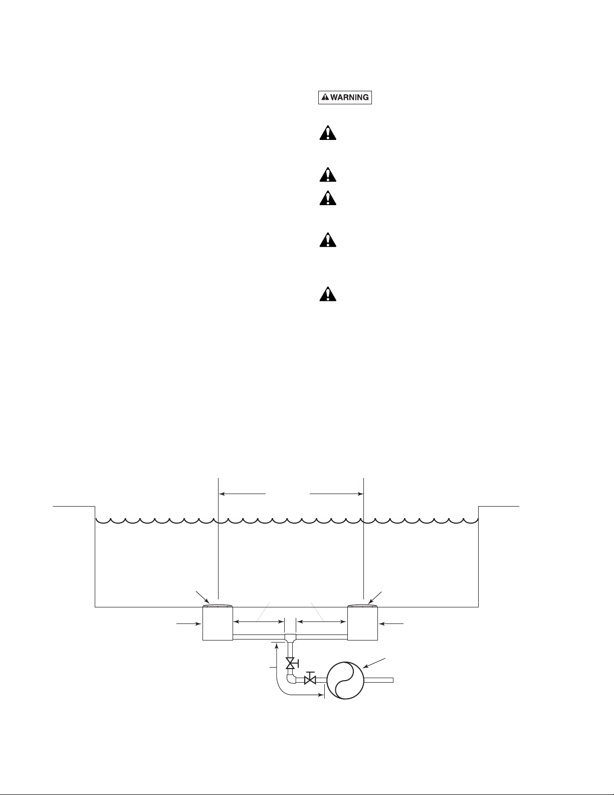
Outlets Per Pump
Provide at least two hydraulically balanced main drains,
with covers (see below), for each swimming pool pump
suction line. The centers of the main drains (suction
fittings) must be at least three feet apart.
The system must be built so that it cannot operate with the
pump drawing water from only
one
main drain (that is, there
must be at least two main drains connected to the pump
whenever it is running). (See Figure 1). However, if two main
drains run into a single suction line, the single suction line
may be equipped with a valve which will shutoff
both
main
drains from the pump (see Figure 1).
More than one pump can be connected to a single
suction line as long as the requirements above are met.
Water Velocity
The maximum water velocity through any suction outlet
must be 1.5 feet per second unless the outlet complies
with the latest ASME/SNSI Specification for
Suction
Fittings For Use in Swimming Pools, Spas, Hot Tubs, and
Whirlpool Bathtub Applications.
In any case, do not
exceed the suction fittings maximum designed flow rate.
If 100% of the pump’s flow comes from the main drain
system, the maximum water velocity in the pump suction
hydraulic system must be six feet per second or less even
if one main drain (suction fitting) is completely blocked.
The flow through the remaining main drain(s) must
comply with the latest ASME/ANSI Specification for
Suction Fittings For Use in Swimming Pools, Spas, Hot
Tubs, and Whirlpool Bathtub Applications.
ELECTRICAL
Hazardous voltage. Can shock, burn or cause
death. Ground pump before connecting to power supply.
Ground motor before connecting to electrical
power supply! Failure to ground pump motor can
cause serious or fatal electrical shock hazard!
Do not ground to a gas supply line!
To avoid dangerous or fatal electrical shock, turn
OFF power to motor before working on electrical
connections.
Ground Fault Circuit Interrupter (GFCI) tripping
indicates an electrical problem. If GFCI trips and
will not reset, have a qualified electrician inspect and
repair electrical system.
Exactly match supply voltage to nameplate voltage!
Incorrect voltage can cause fire or seriously
damage motor and voids warranty! If in doubt consult a
licensed electrician.
Voltage:
Voltage at motor must be not more than 10% above or
below motor nameplate rated voltage or motor may overheat, causing overload tripping and reduced component
life. If voltage is less than 90% or more than 110% of rated
voltage when motor is running at full load, consult power
company.
At Least
3 Feet
Suction Outlet
(Main Drain)
Suction Outlet
(Main Drain)
IAPMO Certified
Anti-entrapment
Cover or Suction Fitting,
screw-fastened to
Main Drain Sump
IAPMO Certified
Anti-entrapment
Cover or Suction Fitting,
screw-fastened to
Main Drain Sump
Pump
Valves OK between
pump and Tee
No valves between
Tee and Main Drains
2762 0197
Figure 1 – Recommended pump suction layout.
Page 5

5
Grounding/Bonding:
Install, ground, bond and wire motor according to local or
National Electrical Code requirements.
Permanently ground motor. Use green ground terminal
provided under motor canopy or access plate (See Figure 2);
use size and type wire required by code. Connect motor
ground terminal to electrical service ground.
Bond motor to pool structure. Use a solid copper
conductor, size No. 8 AWG (8.4 sq. mm) or larger. Run
wire from external bonding lug (see Figure 2) to reinforcing
rod or mesh.
Connect a No. 8 AWG (8.4 sq. mm) solid copper bonding
wire to the pressure wire connector provided on the motor
housing and to all metal parts of the swimming pool, spa, or
hot tub and to all electrical equipment, metal piping or
conduit within 5 feet (1.5 m) of the inside walls of
swimming pool, spa, or hot tub.
Wiring:
Pump must be permanently connected to circuit. Table I
gives correct wire and circuit breaker sizes for the pump
alone. If other lights or appliances are also on the same
circuit, be sure to add their amp loads to pump amp load
before figuring wire and circuit breaker sizes. (If unsure how
to do this or if this is confusing, consult a licensed
electrician.) Use the load circuit breaker as the master on-off
switch.
Install a Ground Fault Circuit Interrupter (GFCI) in circuit;
it will sense a short-circuit to ground and disconnect
power before it becomes dangerous to pool users. For size
of GFCI required and test procedures for GFCI, see
manufacturer’s instruction.
In case of power outage, check GFCI for tripping (which
will prevent normal pump operation). Reset if necessary.
NOTICE: If you do not use conduit when wiring motor, be
sure to seal wire opening on end of motor to prevent dirt,
bugs, etc., from entering.
NOTICE: Three-phase models require magnetic motor
starters and extenal overload protection. If in doubt about
the procedure, consult a licensed electrician. See Figure 3
for wiring connection diagrams. See Table 1 for correct wire
and circuit breaker sizes.
Figure 2: Typical ground screw and bonding lug locations
BONDING
LUG
GREEN
GROUND
SCREW
510 0993
TABLE I - RECOMMENDED CIRCUIT BREAKER SIZE AND WIRING DATA
Branch Wire Wire Gauge Size
Model Motor Voltage/ Max. Load Circuit Breaker Temp. Dist. in Ft. (M)-Service Motor
No. H.P. Hz/Phase Amps Rating (amps) Rating-°C 0-100’ (0-30) 101-200’ (31-60) 201-300’ (61-90)
CF6EF-81L 1-1/2 230V/60/1 10.4 15 75 14(2) 14(2) 12(3)
CF6EG-82L 2 230V/60/1 11.2 15 75 14(2) 14(2) 12(3)
CF6H-123 3 230V/60/1 17.2 30 75 10(5.5) 10(5.5) 10(5.5)
CF6H3-123
3 208-230/460V/60/3 9.8-9.6/4.8 15/15 75 14/14(2/2) 14/14(2/2) 14/14(2/2)
CF6H3-123SA
AWG
(mm
2
)
Wire
Gauge
Size
}
Figure 3: 3-Phase connection diagram. If the diagram on the
motor nameplate does not match this one, follow the motor
nameplate.
4–Brown
5–Orange
6–Black
1–Red
7–Purple
2–White
8–Gray
3–Blue
9–Pink
5
L1
L2
L3
Line
Line
Line
4–Brown
7–Purple
5–Orange
8–Gray
6–Black
9–Pink
1–Red
2–White
3–Blue
D
5
F
L1
L2
L3
Line
Line
Line
Yellow
Yellow
Thermostat
Leads
To reverse the motor, interchange any two line leads (L1, L2, L3)
208-230 Volts 460 Volts
Page 6

6
OPERATION
NEVER run pump dry. Running pump dry may
damage seals, causing leakage and flooding. Fill
pump with water before starting motor.
Before removing trap cover:
1. STOP PUMP before proceeding.
2. CLOSE GATE VALVES in suction and discharge
pipes.
3. RELEASE ALL PRESSURE from pump and piping
system.
If pump is being pressure tested, be sure pressure
has been released before removing trap cover.
Fire and burn hazard. Modern motors run at
high temperatures. To reduce the risk of fire, do not allow
leaves, debris, or foreign matter to collect around the pump
motor. To avoid burns when handling the motor, let it cool
for 20 minutes before trying to work on it. An automatic
internal cutoff switch protects the motor from heat damage
during operation.
Do not block pump suction! To do so with body may
cause severe or fatal injury. Small children using pool
must ALWAYS have close adult supervision.
Priming Pump:
Release all pressure from filter, pump and piping system; see
the filter owner’s manual.
In a flooded suction system (water source higher than
pump), pump will prime itself when suction and discharge
valves are opened.
If pump is not in a flooded suction system, unscrew T-bolt
trap handles and remove trap cover; fill trap and pump with
water.
Clean and lubricate trap cover O-Ring with petroleum jelly
each time it is removed.
Replace trap cover on trap; tighten T-bolt trap handles.
Pump should prime now. Priming time will depend on
vertical length of suction lift and horizontal length of
suction piping.
If pump does not prime, make sure that all valves are open,
suction pipe end is under water and that there are no leaks
in suction pipe. See Troubleshooting Guide, Page 9.
STORAGE/WINTERIZING
Allowing pump to freeze will damage pump and
void warranty!
Do not use anti-freeze solutions (except propylene
glycol) in your pool/spa system. Propylene glycol is
non-toxic and will not damage plastic system
components; other antifreezes are highly toxic and may
damage plastic components in the system.
Drain all water from pump and piping when expecting
freezing temperatures or when storing pump for a long time
(see instructions below).
Keep motor dry and covered during storage.
To avoid condensation/corrosion problems, do not cover
pump with plastic film or bags.
For outdoor/unprotected installations:
1. Enclose entire system in a weatherproof enclosure.
2. To avoid condensation/corrosion damage, allow
ventilation; do not wrap system in plastic film.
3. Use a 40% propylene glycol/60% water solution to
protect pump to -50 degrees F.
Draining Pump
1. Pump down water level below all inlets to the pool.
Hazardous voltage. To avoid dangerous
or fatal electrical shock hazard, turn OFF power to
motor before draining pump or working on pump or
motor.
2. Remove trap cover and use low pressure air to blow
accumulated water from the piping system.
3. Cap inlet piping after draining to keep water out of the
pipes.
4. To prevent pump from freezing, remove trap cover and
drain the tank body through the drain plug (Key 10,
Page 10). Clean pump thoroughly; replace trap cover.
6. Be sure motor is kept dry and covered.
Hazardous suction.
Can trap hair or
body parts, causing
severe injury
or death.
Do not block
suction.
Page 7

7
Startup For Winterized Equipment
1. Remove any temporary weather protection placed
around system for shutdown.
2. Follow filter manufacturer’s instructions for reactivation
of the filter.
3. Inspect all electrical wiring for damage or deterioration
over the shutdown period. Have a qualified serviceman
repair wiring as needed.
4. Inspect and tighten all watertight connections.
5. Open all valves in suction and return piping.
6. Remove any winterizing plugs in piping system.
7. Drain all anti-freeze from system.
8. Close all drain valves and replace all drain plugs in
system.
9. Prime pump according to instructions on Page 6.
PUMP SERVICE
Hazardous voltage. Can shock, burn or cause
death. Disconnect power before working on pump or
motor.
Pump should only be serviced by qualified personnel.
Be sure to prime pump (Page 6) before starting.
Before removing trap cover:
1. STOP PUMP before proceeding.
2. CLOSE GATE VALVES in suction and discharge
pipes.
3. RELEASE ALL PRESSURE from pump and piping
system.
To avoid dangerous or fatal electrical
shock hazard, turn OFF power to motor before
working on pump or motor!
Aside from lubricating trap cover O-Ring, no lubrication or
mechanical maintenance is needed beyond reasonable care
and periodic cleaning.
If shaft seal is worn or damaged, repair as follows:
Pump Disassembly:
Disconnect power to pump motor.
Be sure gate valves on suction and return piping are closed
before starting work.
Release all pressure by opening all vents before starting
work.
1. Drain pump by removing drain plugs on bottom of
pump body and trap body.
2. Be sure there is no pressure in trap body; remove trap
cover.
3. Remove nuts (Key No. 11A, Page 10), which hold volute
in place, thus releasing the volute from the adapter.
4. Hold the motor shaft extension stationary with pliers,
and turn the impeller counter-clockwise until it is free
from the shaft.
NOTICE: 3-Phase motors use an impeller screw.
Remove the impeller screw (left-hand thread—turn
clockwise) before removing impeller. Inspect the washer
for damage, cracks, etc. Replace if necessary.
5. Remove the adapter (Key No. 4) from the motor by
removing the capscrews (Key No. 5).
REMOVAL OF OLD SEAL /
INSTALLATION OF NEW SEAL
1. Drive the old seal out of the adapter. Use a piece of pipe
or tubing as shown in Figure 4.
2. Clean the cavity in the adapter. Before installing, coat
seal case with sealant compound. Press seal into adapter
with a tube or pipe of the correct size to press on the seal
rim only, as shown in Figure 5.
NOTICE: Do not touch or scratch the polished carbon
face of the seal with the pressing tool.
Figure 4
Figure 5
Page 8

8
3. Pry loose the ceramic seal in impeller, apply screwdriver
between seat and cavity in impeller (Figure 6). Clean
cavity from which seat was removed.
4. Lubricate the rubber ring in the impeller with a soap
solution. Press seat into impeller cavity (Figure 7). If a
tool or pipe is necessary to press ceramic seat correctly,
use a cardboard disc or washer to protect the highly
polished ceramic surface of the new seal.
Pump Reassembly:
1. Loosen shaft extension (Key No. 2), so it may be moved
along the shaft with ease. Replace adapter on motor and
tighten capscrews (Key No. 5).
2. Make certain seal faces are clean. Hold the motor shaft
extension stationary and tighten impeller on to shaft.
NOTICE: 3-Phase models use an impeller screw. For
these models, install the impeller washer and lock screw
(left-hand thread—turn counterclockwise) before
proceeding to Step 3.
3. Leaving volute gasket off, place volute on adapter and
tighten nuts (Key No. 11A).
4. Push shaft extension and impeller toward volute until
impeller touches volute. Tighten set screws (Key No. 3)
in place. Remove volute and install gasket (Key No. 8).
Place volute on adapter and tighten nuts (Key No. 11A).
By this procedure, the proper clearance between
impeller face and volute has been established.
Figure 6
Figure 7
Page 9

9
Hazardous voltage. Can shock, burn or cause
death. Disconnect power before working on pump or
motor.
Read and understand safety and operating
instructions in this manual before doing any work
on pump!
Only qualified personnel should electrically test
pump motor!
FAILURE TO PUMP; REDUCED CAPACITY OR
DISCHARGE PRESSURE
A. SUCTION LEAKS/LOST PRIME:
1. Pump must be primed; make sure that pump volute
and trap are full of water. See priming instructions,
Page 6.
2. Make sure there are no leaks in suction piping.
3. Make sure suction pipe inlet to pump is well below
the water level to prevent pump from sucking air.
4. If suction trap O-Ring is defective, replace it.
5. Suction lift of 8 feet (2.4M) will reduce performance.
Suction lift of more than 10 feet (3M) will prevent
pumping and cause pump to lose prime. In either
case, move pump closer (vertically) to water source.
Make sure suction pipe is large enough.
B. CLOGGED PIPE/TRAP/IMPELLER, WORN IMPELLER:
1. Make sure suction trap is not clogged; if it is, clean
trap and strainer.
2. Make sure impeller is not clogged (follow instructions
under “Removing Old Seal,” Page 7; check impeller
for clogging; follow instructions under “Installing New
Seal,” Page 7 for reassembly).
3. Impeller may be worn. If so, order replacement parts
from Repair Parts List, Page 10.
4. Pump may be trying to push too high a column of
water. If so, a “higher head” pump is needed.
C. ELECTRICAL
1. Pump may be running too slowly; check voltage at
motor terminals and at meter while pump is running. If
low, see wiring instructions or consult power company. Check for loose connections.
2. Pump may be too hot.
A. Check line voltage; if less than 90% or more than
110% of rated voltage
consult a licensed electrician.
B. Increase ventilation.
C. Reduce ambient temperature.
D. Tighten any loose connections.
D. MECHANICAL TROUBLES AND NOISE
1. If suction and discharge are not adequately supported,
pump assembly will be strained. See “Installation,”
Page 3.
2. Do not mount pump on a wooden platform!
Securely mount on a concrete platform for quietest
performance.
TROUBLESHOOTING GUIDE
Page 10

10
7A
6108 1009
EXPLODED VIEW
“CF6” BRONZE SERIES
Self Priming Centrifugal Pump
REPAIR PARTS LIST
Key Part CF6EF-81L CF6EG-82L CF6H-123 CF6H3-123
Key Part CF6EF-81L CF6EG-82L CF6H-123 CF6H3-123SA
No. Description Qty. 1-1/2 HP 230V 2 HP 230V 3 HP 230V 3 HP 230/460V
1 Motor 1 AE600FHL AE600GHL C218-195 C218-1612
1A Lug - Bonding 1 U17-568 U17-568 U17-568 U17-568
1B Screw - #10 - 32 x 1/2" 1 U30-692SS U30-692SS U30-692SS U30-692SS
2 Stub Shaft Assembly 1 C110-17 C110-17 C110-17 C110-17A
3 Set Screw 1/4 - 20 x 5/16" 3 U30-754SS U30-754SS U30-754SS U30-754SS
4 Adapter 1 C2-57D C2-57D C2-57D C2-57D
5 Capscrew - 3/8 - 16 x 5/8" 4 U30-72SS U30-72SS U30-72SS U30-72SS
6 Shaft Seal 1 U109-136SS U109-136SS U109-136SS U109-136SS
7 Impeller 1 C5-181D C5-182D C5-203D C5-203D
7A Impeller Screw 1 – – – C30-20
• Impeller Washer 1 – – – U43-51D
8 Gasket 1 C20-72 C20-72 C20-72 C20-72
9 Volute & Trap Body 1 C1-201DB C1-201DB C1-201DB C1-201DB
10 Pipe Plug, 1/4" NPT 2 U78-57DT U78-57DT U78-57DT U78-57DT
11 Stud - 3/8 - 16 x 1-7/16" 4 U30-36SS U30-36SS – –
11 Stud - 3/8 x 1-1/4" 4 – – U30-22SS U30-22SS
11A Nut 3/8-16 4 U36-38SS U36-38SS U36-38SS U36-38SS
12 Trap Cover 1 C3-78D C3-78D C3-78D C3-78D
13 Cord Ring 1 U9-46 U9-46 U9-46 U9-46
14 Trap Handle 2 C154-25 C154-25 C154-18D C154-18D
15 Strainer Basket 1 C108-11P C108-11P C108-11P C108-11P
• “Use Copper Conductors” 1 U27-317 U27-317 U27-317 U27-317
• “For Use w/Pools & Spas” 1 U27-425 U27-425 U27-425 U27-425
• Model Plate 1 U33-6 U33-6 U33-6 U33-6
• “Caution...permanent pools” 1 U27-599 U27-599 U27-599 U27-599
• “Caution...Rotary seal...” 1 U63-13 U63-13 U63-13 U63-13
• Decal ‘230 Volts’ 1 U27-153 U27-153 U27-153 U27-153
• “Suitable for outdoor use...” 1 U27-255 U27-255 U27-255 U27-255
SERVICE KITS
Seal and Gasket Kit 1 PP1150 PP1150 PP1150 PP1150
Trap Basket & O-Ring Kit 1 PP2061 PP2061 PP2061 PP2061
Lock Handle Kit 1 PP2050 PP2050 PP2050 PP2050
• Not illustrated
Page 11

11
Page 12

Complete bottom portion completely and mail to Sta-Rite, Attn.: Warranty Dept., 293 Wright St., Delavan , WI 53115
Warranty Registration Card
Name
Address
City State Zip
Installation (or Purchase) Date
Product Purchased
Model Number
I New installation I Replacement
Years pool has been in service I less than 1 II 1-3 I 3-5 II 5-10
This product was purchased from:
Company name
Address
City State Zip
For technical information about this product, contact the
installer or call Customer Support at:
Phone: (800) 831-7133 Fax: (800) 284-4151
Visit www.pentairwater.com and staritepool.com
S948 Rev A (11-13-09)
PENTAIR WATER POOL AND SPA
®
LIMITED WARRANTY
This product is manufactured by Pentair Water Pool and Spa, Inc. and is warranted to be free of defects in material and/or workmanship for one (1)
year from the original date of installation.
The foregoing warranties relate to the original consumer purchaser (“Purchaser”) only. Pentair Water Pool and Spa, Inc. shall have the option to
repair or replace the defective product, at its sole discretion. Purchasers must pay all labor and shipping charges necessary to replace the product
covered by this warranty. Requests for warranty service must be made through the installing dealer. This warranty shall not apply to any product that
has been subject to negligence, misapplication, improper installation or maintenance, or other circumstances which are not in Pentair Water Pool
and Spa’s direct control. Failure to have product installed by a professional in compliance with local codes will void any and all manufacturers
warranty.
This warranty sets forth Pentair Water Pool and Spa’s obligation and Purchaser’s exclusive remedy for defective products.
PENTAIR WATER POOL AND SPA SHALL NOT BE LIABLE FOR ANY CONSEQUENTIAL, INCIDENTAL OR CONTINGENT DAMAGES
WHATSOEVER.
THE FOREGOING WARRANTIES ARE EXCLUSIVE AND IN LIEU OF ALL OTHER EXPRESS WARRANTIES. IMPLIED WARRANTIES,
INCLUDING BUT NOT LIMITED TO THE IMPLIED WARRANTIES OF MERCHANTABILITY AND FITNESS FOR A PARTICULAR PURPOSE,
SHALL NOT EXTEND BEYOND THE DURATION OF THE APPLICABLE EXPRESS WARRANTIES PROVIDED HEREIN.
Some states do not allow the exclusion or limitation of incidental or consequential damages or limitations on how long an implied warranty lasts, so
the above limitations or exclusion may not apply to you. This warranty gives you specific legal rights and you may also have other rights which vary
from state to state.
Supersedes all previous publications.
S948 Rev. A (11/25/2009)
 Loading...