

Page 1
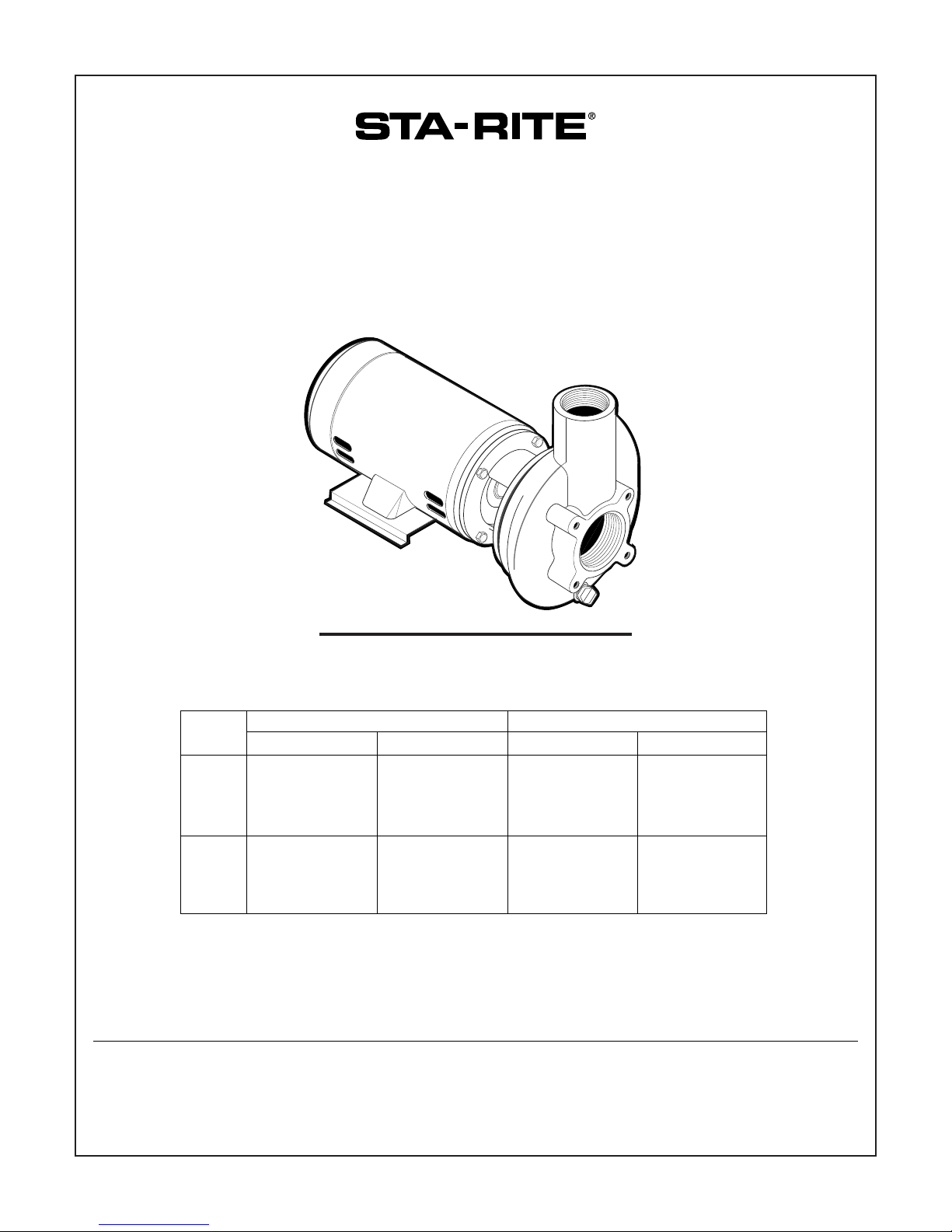
60 CYCLE “C” AND “CC” SERIES
CENTRIFUGAL PUMPS
FOR SWIMMING POOL USE
O W N E R’ S M A N U A L
INSTALLATION, OPERATION & PARTS
Sta-Rite Pool/Spa Group
293 Wright Street, Delavan, WI 53115
North America: 800-752-0183, FAX 800-582-2217
International: 262-728-5551, FAX: 262-728-4461, TELEX: ITT 4970245
www.sta-ritepool.com
Union City, TN • Delavan, WI • Mississauga, Ont. • Murrieta, CA
Printed in U.S.A. © 2002, Sta-Rite Industries, Inc. S408 (Rev. 12/10/02)
This manual should be furnished to
the end user of this pump; its use will
reduce service calls and chance of
injury and will lengthen pump life.
230/460V 200V
HP Medium Head High Head Medium Head High Head
3 CMH-136 CHH-137 CM2H-136 CH2H-137
CMH3-136 CHH3-137 CM2H3-136 CH2H3-137
CCMH-136S CCHH-137S CCM2H-136 CH2H3-137
CCMH3-136S CCHH3-137S CCM2H3-136 CCH2H3-137
5 CHJ-138
CCHJ-138
CHJ3-138 CH2J3-138
CCHJ3-138 CCH2J3-138
MODELS
Page 2

2
‘
C’ and
‘
CC’ SERIES
CENTRIFUGAL PUMP and TRAP
To avoid unneeded service calls, prevent possible injuries, and get the most
out of your pump, READ THIS MANUAL CAREFULLY!
The Sta-Rite ‘C’ and ‘CC’ Series Centrifugal pump:
• Is designed for use with commercial swimming pools or as a centrifugal
pump.
• Is an excellent performer; durable, reliable.
Table of Contents
Safety Instructions ........................................................................................3
Uncrating and Inspection..............................................................................4
Installation.................................................................................................4-6
Electrical....................................................................................................7-8
Operation .....................................................................................................9
Service .................................................................................................10-12
Troubleshooting Guide ...............................................................................13
Repair Parts List .....................................................................................14-15
Warranty.....................................................................................................16
Page 3
3
READ AND FOLLOW SAFETY
INSTRUCTIONS!
This is the safety alert symbol. When you see this symbol on your system
or in this manual, look for one of the following signal words and be alert
to the potential for personal injury.
warns about hazards that will cause death, serious personal
injury, or major property damage if ignored.
warns about hazards that can cause death, serious personal
injury, or major property damage if ignored.
warns about hazards that will or can cause minor personal injury
or property damage if ignored.
NOTICE indicates special instructions not related to hazards.
Carefully read and follow all safety instructions in this manual and on equipment. Keep safety labels in good condition; replace if missing or damaged.
Incorrectly installed or tested equipment may fail, causing
severe injury or property damage.
Read and follow instructions in owner's manual when installing
and operating equipment. Have a trained pool professional
perform all pressure tests.
1. Do not connect system to a high pressure or city water system.
2. Use equipment only in a pool or spa installation.
3. Install pump with at least 2 hydraulically balanced main drains equipped
with correctly installed, screw-fastened, anti-entrapment certified covers.
See Page 4.
4. Trapped air in system can cause explosion. BE SURE all air is out of system
before operating or testing equipment.
Before pressure testing, make the following safety checks:
• Check all clamps, bolts, lids, and system accessories before testing.
• Release all air in system before testing.
• Tighten Sta-Rite trap lids to 25 ft. lbs. (3.5 kg-m) torque for testing.
• Water pressure for test must be less than 25 PSI (7.5 kg/cm
2
).
• Water Temperature for test must be less than 100oF. (38oC).
• Limit test to 24 hours. After test, visually check system to be sure it is ready
for operation. Remove trap lid and retighten hand tight only.
NOTICE: These parameters apply to Sta-Rite equipment only.
For non-Sta-Rite equipment, consult manufacturer.
IMPORTANT
SAFETY
INSTRUCTIONS
Always follow basic safety precautions with this equipment, including the following.
To reduce the risk of
injury, do not permit children to
use this product unless they are
closely supervised at all times.
This pump is for use
with permanently installed pools
and may also be used with hot
tubs and spas if so marked. Do
not use with storable pools. A
permanently installed pool is constructed in or on the ground or in
a building such that it cannot be
readily disassembled for storage.
A storable pool is constructed so
that it may be readily disassembled for storage and reassembled
to its original integrity.
SAVE THESE
INSTRUCTIONS
Page 4

4
UNCRATING AND INSPECTION
Handle with care.
Check items received against packing list to be sure that all equipment has
been received.
Inspect for shipping damage. If found, file claim with carrier immediately.
Cleanup
Clean up all trash and other materials which will interfere with installation
from foundation and surrounding area.
For easy assembly, make sure all threaded joints and mating surfaces are
clean. If necessary, clean with wire brush and solvent.
To reduce danger of explosion and fire, do not use gasoline as a
cleaning solvent.
Remove all foreign material (packing, etc.) from pump and strainer.
INSTALLATION
Only qualified, licensed personnel should install pump and wiring.
Foundation
Foundation must:
Be Solid - Level - Rigid - Vibration free.
Be provided with necessary hold-down bolts, washers, and shims.
Allow pump inlet to be as close to water level as possible.
Use short, direct suction pipe (to reduce friction losses).
Locate pump below pool water level (pump is not self priming).
Allow for shutoff valves in suction and discharge piping.
Have adequate floor drainage to prevent flooding.
Be protected from excess moisture.
Allow adequate access and include suction and discharge (isolation) valves
for servicing pump and piping.
POOL PUMP SUCTION
REQUIREMENTS
Pump suction is hazardous and can trap and drown or disembowel bathers. Do not use or allow anyone else to use a pool, spa, or hot tub
unless it has at least two suction outlets to each pump suction line (see
“Outlets Per Pump,” Page 5). Do not use or operate swimming pools, spas,
or hot tubs if a suction outlet cover is missing, broken, or loose. Follow the
guidelines below for a pump installation which minimizes risk to users of
pools, spas, and hot tubs.
Entrapment Protection
The pump suction system must provide protection against the hazard of
suction entrapment or hair entrapment/entanglement.
Suction Outlet Covers
All suction outlet covers must be maintained. They must be replaced if
cracked, broken, or missing.
See Page 5 for outlet cover certification requirements.
All suction outlets must have correctly installed, screw-fastened covers in
place.
Page 5
5
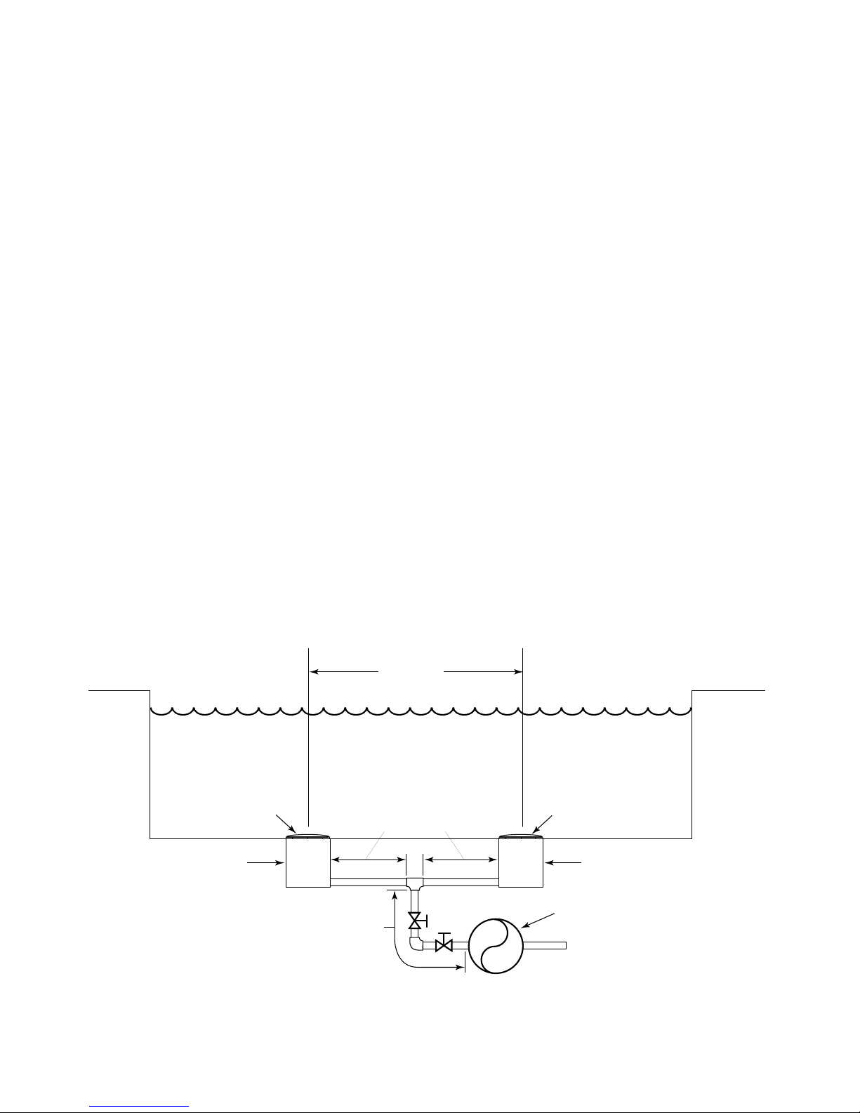
Outlets Per Pump
Provide at least two hydraulically balanced main drains, with covers (see
above), for each swimming pool pump suction line. The centers of the main
drains (suction fittings) must be at least three feet apart.
The system must be built so that it cannot operate with the pump drawing
water from only one main drain (that is, there must be at least two main drains
connected to the pump whenever it is running). (See Figure 1). However, if
two main drains run into a single suction line, the single suction line may be
equipped with a valve which will shutoff both main drains from the pump
(see Figure 1).
More than one pump can be connected to a single suction line as long as the
requirements above are met.
Water Velocity
If 100% of the pump’s flow comes from the main drain system, the maximum
water velocity in the pump suction hydraulic system must be seven feet per
second or less even if one main drain (suction fitting) is completely blocked.
The flow through the remaining main drain(s) must comply with the latest
ASME/ANSI Specification for Suction Fittings For Use in Swimming Pools,
Spas, Hot Tubs, and Whirlpool Bathtub Applications.
Piping – General
System piping must be at least equal to size of pump connections.
To prevent strain on the pump casing and foundation, pipe and fittings must
be aligned to pump without forcing.
To avoid strains on the pump, support both suction and discharge pipes
independently. Place these supports near the pump.
To avoid a strain left by a gap at the last connection, start all piping at the
pump and run pipe away from the pump.
Figure 1 – Recommended pump suction layout.
Anti-entrapment
Cover, screw-fastened
to Main Drain Sump
Main Drain Main Drain
Valves OK between
pump and Tee
At Least
3 Feet
No valves between
Tee and Main Drains
Anti-entrapment
Cover, screw-fastened
to Main Drain Sump
Pump
2515 0497
Page 6

6
Piping – Suction
Risk of severe injury or drowning from hair or body
entrapment. To reduce risk of entrapment against pump suction opening,
connect pump to multiple drains and skimmers of non-entrapment design.
See “Pool Pump Suction Requirements,” Pages 4 and 5.
NOTICE: If pump suction becomes clogged, pump will cavitate, damaging
pump internal parts. Keep suction pipe clear of debris, dirt, etc.
NOTICE: To prevent flooding when removing pump for service, all flooded
suction systems must have valves in suction and discharge pipes.
Never use a suction pipe smaller than the pump suction connection.
Use larger pipe as required to keep water velocity below seven feet per
second or local construction code limits, whichever is lower.
Pump must be installed in a positive suction system – it is not self priming and
will not lift water if suction pipe is empty.
When using reducer to connect to pump flange, use an eccentric reducer with
the straight side on top.
Piping – Discharge
Maximum water velocity should be 10 feet per second. To minimize friction
losses, make piping one size larger than pump openings.
Fittings restrict flow; for best performance use fewest possible fittings.
Avoid fittings which could cause an air trap.
Pool fittings must conform to International Association of Plumbing and
Mechanical Officials (IAPMO) standards.
Strainer
Maximum hydrostatic test pressure is 25 PSI (172 kPa) water
pressure. To avoid explosion hazard, DO NOT test strainer
with air pressure. Air pressure in strainer can blow cover off of
strainer body, which can cause severe or fatal injury. Release
ALL air before hydrostatically testing strainer.
To avoid breaking pump or putting unnecessary strains on pump or strainer
body, support pipe independently of pump/strainer.
Center the strainer cover when installing it (especially when pressure testing).
When installing cover, clean O-Ring groove in strainer body, and lubricate
with petroleum jelly as follows:
A. O-Ring;
B. Sealing surfaces of strainer cover and body;
C. Threads and faces of wing nuts.
This will prevent corrosion, improve seal, and ease maintenance.
If strainer is installed backwards, debris will collect in suction pipe instead of
in strainer basket. Install strainer with cast-on flow arrows pointing in direction of water flow.
Basket will only go into strainer one way; don’t force it.
Hazardous suction.
Can trap hair or
body parts, causing
severe injury
or death.
Do not block
suction.
Page 7

7
ELECTRICAL
Disconnect power at service panel before connecting motor.
Ground motor before connecting to electrical power supply.
Failure to ground motor can cause severe or fatal electrical
shock hazard.
Do not ground to a gas supply line.
To avoid dangerous or fatal electrical shock, turn OFF power to motor
before working on electrical connections.
Supply voltage must be within ±10% of nameplate voltage. Incorrect
voltage can cause fire or seriously damage motor and voids warranty.
If in doubt consult a licensed electrician.
Use wire size specified in Wiring Chart. If possible, connect pump to a
separate branch circuit with no other appliances on it.
Single phase motors come factory wired for 230 volt operation. Do not alter
wiring in single phase motors. Match motor voltage to power supply voltage.
Do not connect three phase motors to single phase power supply or single
phase motors to three phase power supply.
All electrical wiring, grounding, and bonding must be done by a licensed
electrical contractor who is familiar with commercial swimming pool installations and electrical codes and requirements. Wire sizing, wire type, branch
circuit fuse protection, motor starter, control equipment, and related items
must meet National Electrical Code and local code requirements.
Wiring
1. Install, ground, wire and maintain this pump in accordance with your local
electrical code and all other codes and ordinances that apply. Consult your
local building inspector for local code information.
2. Ground the pump permanently using a wire of size and type specified by
local or National Electrical Code.
Do not ground to a gas supply line.
3. Connect ground wire first. Connect to ground first, then to green grounding
terminal provided (identified as GRD or ). Make ground connection to
this terminal. Do not connect motor to electrical power supply until unit is
permanently grounded; otherwise serious or fatal electrical shock hazard
may be caused.
4. For best ground connection, connect ground wire to a grounded lead in the
service panel.
Bond motor to pool structure according to local or National Electrical Code.
Use a solid copper conductor, size No. 8 (6.0 mm
2
) AWG or larger.
Hazardous voltage.
Can shock, burn,
or cause death.
Ground pump before
connecting to
power supply.
Page 8

8
Fire Hazard. Before using pump, check your motor nameplate
for voltage. Your electric supply voltage and the stamped nameplate voltage
must agree. Motors stamped 200 volts or 230 volts, must be used with that
voltage only. Motors stamped with two voltages (for example 230/460 volts),
may be used with either supply voltage. For these motors check connections
against wiring diagram on motor nameplate and make any changes necessary
to agree with your supply voltage. If in doubt, call a licensed electrician.
Incorrect voltage will cause serious damage to the motor.
Some models are equipped with three phase motors, which require magnetic
starters.
Motors can run in either direction, depending on how they are connected to
the power supply.
To check motors for proper rotation: Remove the motor end cover. This exposes the motor shaft. If hook-up is correct, the shaft will rotate clockwise. If
rotation is not clockwise:
•3 Phase motors: Reverse any two leads to the starter.
•1 Phase motors: See wiring diagram on motor nameplate.
The rotation will now be correct. BE SURE power is off to the motor when
working on electrical connections.
Burn Hazard. Motor normally operates at high temperature and
will be too hot to touch. Before handling pump or motor, stop motor and
allow it to cool for 20 minutes.
TABLE I – ELECTRICAL DATA - FUSING AND WIRING REQUIREMENTS
Serv. to Motor - Dist. in Ft. (M)
Motor Voltage/ Max Load Branch Fuse 0-100' 101-200' 201-300'
HP Hz/Phase Amps Rating Amps* (0-30M) (30-60M) (60-90M)
3 230/60/1 13.4 20 12(3) 12(3) 10(5.5)
3 230/460/60/3 8.6/4.3 15/15 14/14(2/2) 14/14(2/2) 14/14(2/2)
3 200/60/1 17.2 25 10(5.5) 10(5.5) 10(5.5)
3 200/60/3 8.4 15 14(2) 14(2) 14(2)
5 230/60/1 22.0 30 10(5.5) 10(5.5) 8(8.4)
5 230/460/60/3 13.2/6.6 20/15 12/14(3/2) 12/14(3/2) 12/14(3/2)
5 200/60/3 13.8 20 12(3) 12(3) 12(3)
Page 9

9
OPERATION
Hazardous suction. Can trap hair or body parts, causing severe
injury or death by drowning. Do not block pump or strainer
suction with body. Small children using pool must ALWAYS
have close adult supervision!
Do not run pump against closed discharge valve. To do so
can boil water in pump body, which cause pump to explode and can cause
severe burns to people working on pump.
NEVER run pump dry. Running pump dry may damage seals,
causing leakage and flooding. Fill pump with water before starting motor.
Before removing strainer cover:
1. STOP PUMP before proceeding.
2. CLOSE SHUTOFF VALVES in suction and discharge pipes.
3. RELEASE ALL PRESSURE from pump and piping system.
After pressure test, release all pressure before removing strainer cover!
NOTICE: Provide adequate ventilation. Ambient air temperature should be
104°F (40°C) or less.
NOTICE: To prevent corrosion damage, store pool chemicals in another room
away from pump.
Priming Pump
Hazardous Pressure! Before removing strainer cover, remove
vent plug in cover or open filter tank air release valve and release all pressure
from system.
In a flooded suction system open suction/discharge valves to prime. If pump is
not in a flooded suction system, remove strainer cover; fill strainer and pump
with water.
If necessary, use a wrench on flats when removing wing nuts.
When installing cover, clean O-Ring sealing surface on strainer body, and
lubricate with petroleum jelly as follows:
A. O-Ring;
B. Sealing surfaces of strainer cover and body;
C. Threads and faces of wing nuts.
This will prevent corrosion, improve seal, and ease maintenance.
Center strainer cover when installing it (especially when pressure testing).
Hand tighten wing nuts. When tightening, alternate back and forth between
nuts to compress O-Ring evenly.
Maximum wing nut torque is 25 ft.-lbs. (3.5 kg.-m).
Start pump; it should prime now.
If pump does not prime, make sure that all valves are open, suction pipe end
is under water and that there are no leaks in suction pipe. See
Troubleshooting Guide, Page 13.
NOTICE: To avoid corrosion damage to pump and strainer, do not add chemicals to system anywhere on suction side of pump (including into skimmers).
Do not pour chemicals into strainer. Follow chemical manufacturer’s instructions when mixing or adding chemicals to system.
Hazardous
suction.
Page 10

10
‘C’ and ‘CC’ SERIES COMMERCIAL
POOL PUMP DISASSEMBLY/
ASSEMBLY
See Exploded View, Page 14.
Shaft Seal Replacement
NOTICE: The highly polished and lapped faces of the seal are easily dam-
aged. Follow instructions and handle the seal with care.
Be sure unit is grounded and power disconnected before
attempting any work on pump or motor.
Removal of Old Seal
Refer to Figure 2 for Mechanical Seal parts identification. Refer to exploded
view, Page 14, for Key No. references.
1. Disconnect all power to pump.
2. Close suction and discharge valves to isolate pump from system.
3. Drain pump and strainer; be sure to vent pump before opening strainer
cover.
4. Remove motor hold down bolts and the nuts (Key No. 21) holding
adapter/seal plate (Key No. 5) to volute (Key No. 18). Slide motor,
adapter/seal plate and impeller (Key Nos. 1, 5 and 12) backward to clear
volute.
5. Remove impeller screw, washer and gaskets (Key Nos. 13-16) from end of
shaft and slide impeller off of shaft.
6. Unbolt adapter/seal plate from motor.
7. Use two screwdrivers (Figure 3) or bearing puller to carefully separate
motor from adapter/seal plate, bringing rotating half of seal off with
adapter/seal plate. Shaft sleeve (Key No. 10) may come off with seal.
8. Use hammer, if necessary, to drive shaft sleeve out of seal. Clean up shaft
sleeve with emery paper if necessary.
9. Place adapter/seal plate face down on bench and tap old stationary half of
seal out of adapter/seal plate with a screwdriver and hammer (Figure 4).
10. Use a wire brush to thoroughly clean adapter/seal plate cavity. Be sure all
dust and grime are out of seal cavity before installing new seal.
Installing New Seal
1. NOTICE: Seal faces are highly polished and lapped. Handle with care.
Any mar, nick or scratch on seal face will cause it to leak. BE SURE to
install with polished faces toward each other (see Figure 2).
2. Clean polished surface of ceramic seat with clean cloth.
3. Sparingly wet O-Ring around ceramic seat with liquid soap.
4. Press stationary (ceramic) half of seal cavity into cavity firmly and squarely
with thumb pressure. If it does not seat properly, remove and place seal
face up on bench. Re-clean adapter/seal plate cavity. Seal should now seat
correctly.
5. If seal does not seat after re-cleaning adapter/seal plate cavity, place a card-
board washer over polished face of seal and carefully press into place
using a piece of 1” standard pipe as a press (Figure 5).
Hazardous
voltage
Figure 3
Figure 4
Figure 5
Stationary
Figure 2
Seat
1419 1294
Rotating Seat will come off
with adapter/sealplate.
1" Standard Pipe
Rotating
Seat
If Gear Puller is used,
place jackscrew here.
1420 1294 C/CC
Spring
1421 1294
C/CC
Cardboard
Washer
Stationary Seat
(Supplied with seal)
1422 1294 C/CC
Page 11

11
NOTICE: BE SURE you do not scratch seal face.
6. Dispose of cardboard washer and recheck seal face to be sure it is free of
dirt, foreign particles, scratches and grease.
7. Inspect shaft and shaft sleeve to be sure they are clean.
8. Re-install O-Ring, shaft sleeve and slinger (Key No. 2) on shaft.
NOTICE: A small amount of grease or Never-Seez under shaft sleeve will
help prevent shaft and sleeve from freezing together when pump is in service.
9. Remount adapter/seal plate to motor, being careful not to scratch seal face.
10. Sparingly apply liquid soap to inside diameter and outside face of rubber
drive ring on rotating half of seal.
11. Slide seal assembly onto shaft sleeve (sealing face first) far enough so that
seal spring is located on shaft sleeve.
NOTICE: Be careful not to nick carbon seal face when passing it over end
of shaft sleeve.
12. Slide impeller and gaskets (Key Nos. 12 and 11 in Exploded View,
Page 14) onto shaft with key (Key No. 3) in position. Be sure to maintain
proper order as shown on Page 14.
13. Install washer, gaskets, and impeller screw (Key Nos. 13, 14, 15, and 16)
on end of shaft and tighten screw until it is snug. This should locate seal in
place and bring seal faces together.
14. Reinstall motor, adapter and impeller assembly (Key Nos. 1, 5, and 12) on
volute, using new gasket (Key No. 8).
15. Reinstall motor hold-down bolts.
16. Check all bolts for tightness.
17. Close drains; open system valves to fill pump.
18. When pump is full, close vent.
19. Reconnect power to pump and system is ready for operation.
MAINTENANCE - Strainer
Before removing strainer cover, close isolation valves
and open air release valve in filter and release
all pressure.
NOTICE: Do not allow strainer to freeze.
Always close isolation valves before working on the system.
If system will be shut down for one day or more, close isolation valves and
drain strainer and system to prevent corrosion.
Remove cover to allow interior to dry out when storing for the season. When
interior is dry, replace cover.
Remove drain plug when storing for season. Leave plug out until system is
restarted the following season.
To remove strainer cover, unscrew wing nuts. If necessary, use a wrench on
flats when removing wing nuts.
Hazardous
pressure and
risk of flooding
Page 12

12
NOTICE: A clogged basket will cause cavitation, which will damage strainer
basket, impeller, and pump. Clean weekly or each time you vacuum pool,
whichever comes first.
NOTICE: Basket is a close fit in body of strainer. When cleaning basket, do
not deform.
Hose basket out well.
DO NOT hammer on basket or otherwise mistreat it.
When installing cover, clean O-Ring sealing surface on strainer body.
To prevent corrosion, improve seal, and ease maintenance, lubricate O-Ring,
sealing surfaces of strainer cover and body, and threads and faces of wing
nuts with petroleum jelly.
Center strainer cover when installing it (especially when pressure testing).
Hand tighten wing nuts. When tightening, alternate back and forth between
nuts to compress O-Ring evenly.
Maximum wing nut torque is 25 ft.-lbs. (3.5 kg-m).
If possible, protect from weather at all times.
For storage of out door installation:
1. Drain system.
2. Dry as much as possible.
3. Lubricate with petroleum jelly.
4. Reassemble.
5. Leave drain plug out during storage.
Figure 6 – Pressure drop curve for hair and lint strainers.
6
5
4
3
P.S.I. Loss
2
1
Pkg. 51/56 6" Trap
with Basket
Pkg. 98/99 8" Trap
with Basket
0
20 40
60 80 100 120
Flow (GPM)
140
3113 1197
160 180
Page 13

13
SYMPTOM KEY NUMBERS FOR CAUSES
Pump does not deliver liquid 1, 2, 3, 4, 6, 8, 10, 11, 14, 15, 16, 17
Pump delivers too little flow 2, 3, 4, 5, 6, 7, 8, 9, 11, 14, 16, 17, 23, 24
Delivery pressure too low 5, 8, 9, 10, 11, 14, 16, 23, 24
Pump needs too much power 9, 10, 11, 12, 13, 14, 17, 18, 20,21, 23
Seal leaks 18, 20, 25, 26
Pump vibrates or is noisy 2, 3, 4, 6, 7, 15, 17, 18, 19, 20, 21, 22, 24, 25, 26, 27,
28, 29, 30
Motor bearings have short life 18, 20, 21, 22, 25, 26, 27, 28, 29, 30
Pump overheats and/or seizes 1, 4, 15, 16, 18, 21, 22, 25, 26
CAUSES
1. Pump not primed. 16. Parallel operation of pumps unsuited for such operation.
2. Pump or suction pipe not completely full of liquid 17. Foreign matter in impeller.
3. Suction lift rather than positive head installation. 18. Misalignment of pump or piping.
4. Pump cavitating; increase suction pressure. 19. Foundations not rigid.
5. Excessive amount of air or gas in liquid. 20. Shaft bent.
6. Suction pipe inlet not sufficiently submerged. 21. Rotating part rubbing on stationary part.
7. Impeller, suction or strainer partially or 22. Bearings worn.
completely plugged. 23. Wear ring worn.
8. Speed too low. 24. Impeller damaged.
9. Voltage wrong or too low. 25. Shaft running off center due to worn bearings or
10. Wrong direction of rotation. misalignment.
11. System head too high for pump design. 26. Impeller out of balance resulting in vibration.
12. System head too low for pump design. 27. Excessive grease in bearing causing high bearing temperature.
13. Specific gravity of liquid different than design. 28. lack of lubrication.
14. Viscosity of liquid different than design. 29. Dirt in bearings.
15. Pump operating at very low capacity. 30. Rust in bearings due to water getting into motor.
TROUBLESHOOTING GUIDE
Read symptom describing problem below at left. Causes for problems (bottom) are keyed to numbers at right. Check pump
for causes listed at right and correct those that apply.
Hazardous voltage. Can shock, burn or kill.
Page 14

14
1
2
5
3
4
6
7
8
9
10
12
11
17
18
13
14
16
20
21
22
6
15
1904 0795
19
‘
C’ / ‘CC’ Series Centrifugal Pumps
3 and 5 HP Medium and High Head
Model Number
CCMH-136S CMH-136 CCHH-137S CHH-137 CCHJ-138 CHJ-138
CCMJ3-136S CMH3-136 CCHH3-137S CHH3-137 CCHJ3-138 CHJ3-138
CCM2H-136 CM2H-136 CCH2H-137 CH2H-137 CCH2J3-138 CH2J3-138
Key CCM2H3-136 CM2H3-136 CCH2H3-137 CH2H3-137 – –
No. Description Qty. 3 HP 3 HP 3 HP 3 HP 5 HP 5 HP
1 Motor 230V/60H/1 Ph. 1 C218-177 C218-177 C218-177 C218-177 C218-180 C218-180
1 Motor 230/460V/60H/3 Ph. 1 C218-179 C218-179 C218-179 C218-179 C218-182 C218-182
1 Motor 200V/60H/1 Ph. 1 C218-191 C218-191 C218-191 C218-191 – –
1 Motor 200V/60H/3 Ph. 1 C218-178 C218-178 C218-178 C218-178 C218-181 C218-181
2 Water Slinger-1 Ph. 1 C69-15 C69-15 C69-15 C69-15 – –
2 Water Slinger-3 Ph. 1 C69-16 C69-16 C69-16 C69-16 C69-16 C69-16
3 Key, Square 1 U65-42A U65-42A U65-42A U65-42A U65-42A U65-42A
4 O-Ring 1 U9-265 U9-265 U9-265 U9-265 U9-265 U9-265
5 Adapter 1 C2-81 C2-81D C2-81 C2-81D C2-81 C2-81D
6 Lockwasher, 3⁄8”8U43-12ZP U43-12ZP U43-12ZP U43-12ZP U43-12ZP U43-12ZP
7 Capscrew, 3⁄8-16x7⁄8”4U30-73ZP U30-73ZP U30-73ZP U30-73ZP U30-73ZP U30-73ZP
8 Gasket 1 C20-77 C20-77 C20-77 C20-77 C20-77 C20-77
9 Shaft Seal 1 U109-433SS U109-433SS U109-433SS U109-433SS U109-433SS U109-433SS
10 Sleeve 1 C23-58 C23-58 C23-58 C23-58 C23-58 C23-58
11 Gasket, Sleeve 1 C20-101 C20-101 C20-101 C20-101 C20-101 C20-101
12 Impeller (-136, -137, -138) 1 C105-224DD C105-224DD C105-224DB C105-224DB C105-224DE C105-224DE
12 Impeller (-136S) 1 C105-224DG – – – – –
13 Gasket 1 C20-100 C20-100 C20-100 C20-100 C20-100 C20-100
14 Washer, Impeller 1 C43-45SS C43-45SS C43-45SS C43-45SS C43-45SS C43-45SS
15 Gasket 1 C43-46 C43-46 C43-46 C43-46 C43-46 C43-46
16 Screw, Impeller 3⁄8-16x3⁄4”1U30-72SS U30-72SS U30-72SS U30-72SS U30-72SS U30-72SS
17 Wear Ring Only 1 C23-40 C23-40 C23-40 C23-40 C23-40 C23-40
18 Volute Assembly (incl. #20 & 21) 1 C201-174 C201-174D C201-174 C201-174D C201-174 C201-174D
18A Volute Assemby(Incl. #20 Only) 1 C101-167 C101-167D C101-167 C101-167D C101-167 C101-167D
19 Pipe Plug, 1⁄4” NPT 1 U78-941ZPV U78-941ZPV U78-941ZPV U78-941ZPV U78-941ZPV U78-941ZPV
20 Stud, 3⁄8-16x11⁄4”4U30-22SS U30-22SS U30-22SS U30-22SS U30-22SS U30-22SS
21 Nut, Hex 3⁄8x16 4 U36-38C U36-38SS U36-38C U36-38SS U36-38C U36-38SS
22 Pipe Plug, 1⁄4” NPT 1 U78-57SSS U78-57SSS U78-57SSS U78-57SSS U78-57SSS U78-57SSS
•Capscrew 5⁄16-18x3⁄4”4U30-60SS U30-60SS U30-60SS U30-60SS U30-60SS U30-60SS
• Not illustrated.
NOTE: C Series with different numbers (for example CCMH-93) use different parts. Consult factory for older models.
Page 15

15
1839 0695
5
4
3
2
1
6
7
1128 0695
7
3
4
5
2
1
6
8
9
EXPLODED VIEWS
Key Part
No. Description Cast Iron Bronze
1* Lock Handle C154-18D C154-18D
2 Cover - 6” C30-30 C3-78DZZ
2 Cover - 8” C3-105 C3-105D
3 O-Ring - 6” U9-46 U9-46
3 O-Ring - 8” U9-171 U9-171
4 Strainer Basket - 6” C108-11P C108-11P
4 Strainer Basket - 8” C108-34SS C108-34SS
5 Suction Strainer Body - 6” C53-5B C53-5D
5 Suction Strainer Body - 8” C53-21 C53-21D
6 Pipe Plug 1/4” U78-57DT U78-57DT
7 Gasket, Flange C20-19 C20-19
8 Capscrew, 3/8-16x1-3/4” – U30-77C
9 Nut, Hex 3/8-16 – U36-38C
• Capscrew, 5/16-18x7/8” U30-61C(4) U30-61C(4)
Suction Strainer Complete - 6” Pkg. #51 Pkg. #56
Suction Strainer Complete - 8” Pkg. #98 Pkg. #99
Quantity 1 unless otherwise noted ( ).
• Not illustrated.
* 6” has 2 each; 8” has 4 each.
HAIR AND LINT STRAINER
REPAIR PARTS LIST
NOTICE: Strainers
are not included
with pumps.
6” Hair and Lint
Strainer
8” Hair and Lint
Strainer
Page 16

▲ Retain Warranty Certificate (upper portion) in a safe and convenient location for your records.
DETACH HERE: Fill out bottom portion completely and mail within 10 days of purchase/installation to:
▼ Sta-Rite, Attn: Warranty Dept., 293 Wright St., Delavan, WI 53115
Pumps, filters, skimmers, underwater lights (except bulbs),
accessories and fittings manufactured by Sta-Rite are warranted to be free of defects in material and workmanship for
one (1) year from date of installation.
Product specific warranties:
Year from date
of installation
HRPB, DEPB and System 3 – Tanks . . . . . . . . . . . .10 years
Internal filter components and valves . . . . . . . . . 1 year
Max-E-Therm – Pool/Spa Heaters . . . . . . . . . . . . . 2 years
Heater Enclosure only (Upper RH & LH;
lower enclosure; and control board enclosure)… 10 years
Automatic Pool Cleaners including Hose . . . . . . . 2 years
Cristal-Flo filters – Tanks . . . . . . . . . . . .10 years pro-rated*
Valve and internal components. . . . . . . . . . . . . . . 1 year
Posi-Flo II – Tanks . . . . . . . . . . . . . . . . . . . . . . . . .10 years
Elements . . . . . . . . . . . . . . . . . . . . . . . . . . . . . . . . 1 year
PRC Cartridge –
Filter Tanks . . . . . . . . . .5 years pro-rated (1st 2 years full)
Elements . . . . . . . . . . . . . . . . . . . . . . . . . . . . . . . . 1 year
System 3 Above Ground Systems – Tanks . . . . . . .10 years
Pumps / Platform and Internals . . . . . . . . . . . . . . . 1 year
Pumps . . . . . . . . . . . . . . . . . . . . . . . . . . . . . . . . . . . . . 1 year
When equipped with A.O. Smith
2-compartment motors (Does not include
pumps sold as part of a systems package) . . . . . . 2 years
Traps / In-Line Strainers . . . . . . . . . . . . . . . . . . . . . 1 year
Vertical Commercial Filter – Tanks . . . . . . . . . . . .10 years
Internals . . . . . . . . . . . . . . . . . . . . . . . . . . . . . . . . . 1 year
Horizontal Commercial Filter
Tanks . . . . . . . . . . . . . . . . . . . . . . . . . . . . . . . . . . .5 years
(Years 6-9, Prorated declining 20%/year, Yr. 10 - 10%)
Internals . . . . . . . . . . . . . . . . . . . . . . . . . . . . . . . . . 1 year
* Full warranty coverage is in effect for one year after installation. The pro-rated warranty covers the tank only during
the 2nd through 10th year after installation. The amount covered decreases by 10% each year. (ie., 2nd year 90% covered,
3rd year 80% covered, etc.).
The foregoing warranties relate to the original consumer purchaser (“Purchaser”) only. Sta-Rite shall have the option to repair or replace the defective product, at its sole discre-
tion. Purchasers must pay all labor and shipping charges necessary to replace the product covered by this warranty.
Requests for warranty service must be made through the installing dealer. This warranty shall not apply to any product
that has been subject to negligence, misapplication, improper
installation or maintenance, or other circumstances which are
not in Sta-Rite’s direct control.
This warranty sets forth Sta-Rite’s sole obligation and
Purchaser’s exclusive remedy for defective products.
STA-RITE SHALL NOT BE LIABLE FOR ANY CONSEQUENTIAL,
INCIDENTAL OR CONTINGENT DAMAGES WHATSOEVER.
THE FOREGOING WARRANTIES ARE EXCLUSIVE AND IN
LIEU OF ALL OTHER EXPRESS WARRANTIES. IMPLIED WARRANTIES, INCLUDING BUT NOT LIMITED TO THE IMPLIED
WARRANTIES OF MERCHANTABILITY AND FITNESS FOR A
PARTICULAR PURPOSE, SHALL NOT EXTEND BEYOND THE
DURATION OF THE APPLICABLE EXPRESS WARRANTIES
PROVIDED HEREIN.
Some states do not allow the exclusion or limitation of incidental or consequential damages or limitations on how long
an implied warranty lasts, so the above limitations or exclusion may not apply to you. This warranty gives you specific
legal rights and you may also have other rights which vary
from state to state.
Supersedes all previous publications.
Sta-Rite Industries, Inc.,
293 Wright St., Delavan, WI 53115
Warranty Registration Card
Name
Address
City State Zip
Purchase Date
Product Purchased
■■ New installation ■■ Replacement
Type of Pool ■■ Inground ■■ Vinyl ■■ Fiberglass ■■ Gunite
Size of Pool
Years pool has been in service ■■ less than 1 ■■ 1-3 ■■ 3-5 ■■ 5-10
Purchased from:
Company name
Address
City State Zip
Please send me more information on these
other products from Sta-Rite.
■■ Pumps ■■ Filters ■■ Automatic Pool Cleaners
■■ Maintenance Equipment ■■ Test Strips
■■ Heaters
S4877PS (Rev. 5/15/00)
STA-RITE LIMITED WARRANTY
 Loading...