


 Loading...
THERMAL PRINTER TSP650 SERIES
Hardware Manual
Federal Communications Commission
Radio Frequency Interference
Statement
This device complies with Part 15 of the FCC Rules. Operation is subject to the following two conditions: (1) This device may not cause harmful interference, and (2) this device must accept any interference received, including interference that may cause undesired operation.
NOTE: This equipment has been tested and found to comply with the limits for a Class A digital device, pursuant to Part 15 of the FCC Rules. These limits are designed to provide reasonable protection against harmful interference when the equipment is operated in a commercial environment. This equipment generates, uses and can radiate radio frequency energy and, if not installed and used in accordance with the instruction manual, may cause harmful interference to radio communications. Operation of this equipment in a residential area is likely to cause harmful interference in which case the user will be required to correct the interference at his own expense.
This statement will be applied only for the printers marketed in U.S.A.
FCC WARNING
Changes or modifications not expressly approved by the party responsible for compliance could void the user’s authority to operate the equipment.
For compliance with the Federal Noise Interference Standard, this equipment requires a shielded cable.
For RF interference suppression, if a ferrite core is provided with this device, affix it to the interface cable
Statement of
The Canadian Department of Communications
Radio Interference Regulationst
This Class A digital apparatus complies with Canadian ICES-003.
Cet appareil numérique de la classe A est conforme à la norme NMB-003 du Canada.
The above statement applies only to printers marketed in Canada.
Trademark acknowledgments
TSP650: Star Micronics Co., Ltd.
Notice
•All rights reserved. Reproduction of any part of this manual in any form whatsoever, without STAR’s express permission is forbidden.
•The contents of this manual are subject to change without notice.
•All efforts have been made to ensure the accuracy of the contents of this manual at the time of going to press. However, should any errors be detected, STAR would greatly appreciate being informed of them.
•The above notwithstanding, STAR can assume no responsibility for any errors in this manual.
©Copyright 2007-2010 Star Micronics Co., Ltd.
TABLE OF CONTENTS
1. Unpacking and Installation..................................................................................................................... |
1 |
|
1-1. |
Unpacking..................................................................................................................................... |
1 |
1-2. |
Choosing a place for the printer................................................................................................... |
2 |
2. Parts Identification and Nomenclature................................................................................................... |
3 |
|
2-1. |
Cutter Model................................................................................................................................. |
3 |
2-2. |
Tear Bar Model............................................................................................................................. |
3 |
3. Setup.......................................................................................................................................................... |
|
4 |
3-1. |
Connecting the Cable to the PC.................................................................................................... |
4 |
3-2. |
Connecting the Cable to the Printer.............................................................................................. |
5 |
3-3. |
Installing the Printer Software...................................................................................................... |
8 |
3-4. |
Connecting the Optional AC Adapter........................................................................................... |
9 |
3-5. |
Turning Power On...................................................................................................................... |
10 |
3-6. |
Connecting to a Peripheral Unit................................................................................................. |
11 |
3-7. |
Loading the Paper Roll............................................................................................................... |
12 |
4. Attaching the Accessories....................................................................................................................... |
16 |
|
4-1. |
Attaching the Holder Plate......................................................................................................... |
16 |
4-2. |
Attaching the Rubber Feet.......................................................................................................... |
17 |
4-3. |
Switch Cover Installation........................................................................................................... |
18 |
5. Consumable Parts and AC Adapter...................................................................................................... |
19 |
|
5-1. |
Thermal Paper Roll..................................................................................................................... |
19 |
5-2. |
AC adapter (option).................................................................................................................... |
20 |
6. Control Panel and Other Functions...................................................................................................... |
21 |
|
6-1. |
Control Panel.............................................................................................................................. |
21 |
6-2. |
Errors.......................................................................................................................................... |
21 |
6-3. |
Self-Printing................................................................................................................................ |
23 |
7. Adjusting the Near-end Sensor.............................................................................................................. |
24 |
|
8. Preventing and Clearing Paper Jams................................................................................................... |
26 |
|
8-1. |
Preventing Paper Jams................................................................................................................ |
26 |
8-2. |
Removing Paper Jam.................................................................................................................. |
26 |
8-3. |
Releasing a Locked Cutter (Auto Cutter Mode only)................................................................. |
27 |
9. Periodical Cleaning................................................................................................................................ |
28 |
|
9-1. |
Cleaning the Thermal Head........................................................................................................ |
28 |
9-2. |
Cleaning the Rubber Roller........................................................................................................ |
28 |
9-3. |
Cleaning the Paper Holder and the Surrounding Area............................................................... |
28 |
10. Specifications......................................................................................................................................... |
29 |
|
10-1. General Specifications................................................................................................................ |
29 |
|
10-2. |
Auto Cutter Specifications.......................................................................................................... |
30 |
10-3. |
Interface...................................................................................................................................... |
30 |
10-4. |
Electrical Characteristics (AC adapter)...................................................................................... |
30 |
10-5. |
Environmental Requirements..................................................................................................... |
31 |
10-6. |
Reliability Specifications............................................................................................................ |
32 |
11. Dip Switch Setting................................................................................................................................. |
33 |
|
11-1. |
Parallel Interface Model............................................................................................................. |
34 |
11-2. |
RS-232C Interface Model........................................................................................................... |
36 |
11-3. |
USB Interface Model.................................................................................................................. |
39 |
11-4. |
EthernetInterface Model............................................................................................................. |
41 |
12. |
Parallel Interface.................................................................................................................................. |
44 |
13. |
RS-232C Serial Interface..................................................................................................................... |
45 |
|
13-1. Interface Specifications............................................................................................................... |
45 |
|
13-2. RS-232C Connector.................................................................................................................... |
46 |
|
13-3. Cable Connections...................................................................................................................... |
48 |
14. |
USB and Ethernet Interface................................................................................................................ |
49 |
15. |
Peripheral Unit Drive Circuit.............................................................................................................. |
50 |
16. |
Memory Switch Settings...................................................................................................................... |
52 |
17. |
Release History..................................................................................................................................... |
53 |
Please access the following URL |
|
|
http://www.star-m.jp/eng/dl/dl02.htm |
|
|
for the latest revision of the manual. |
|
|
1. Unpacking and Installation
1-1. Unpacking
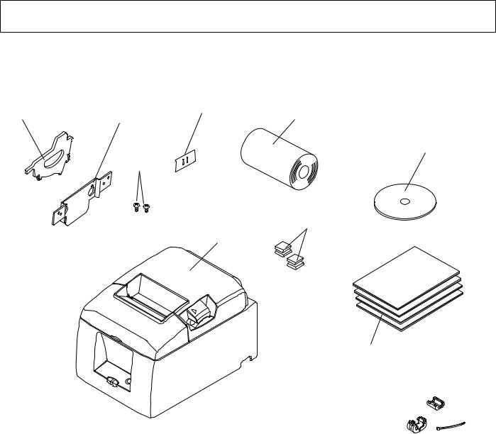
After unpacking the unit, check that all the necessary accessories are included in the package.
Paper roll holder |
Holding plate |
Switch blind |
Paper roll |
CD-ROM
Screws
Rubber feet
Printer
Setup sheets
Note
Note: The ferrite core and fastener provided with your printer depend on your printer configuration.
Fig. 1-1 Unpacking
If anything is missing, contact the dealer where you bought the printer and ask them to supply the missing part. Note that it is a good idea to keep the original box and all the packing materials just in case you need to pack the printer up again and send it somewhere at a later date.
– 1 –
1-2. Choosing a place for the printer
Before actually unpacking the printer, you should take a few minutes to think about where you plan to use it. Remember the following points when doing this.
PChoose a firm, level surface where the printer will not be exposed to vibration.
PThe power outlet you plan to connect to for power should be nearby and unobstructed.
PMake sure that the printer is close enough to your host computer for you to connect the two.
PMake sure that the printer is not exposed to direct sunlight.
PMake sure that the printer is well away from heaters and other sources of extreme heat.
PMake sure that the surrounding area is clean, dry, and free of dust.
PMake sure that the printer is connected to a reliable power outlet. It should not be on the same electric circuit as copiers, refrigerators, or other appliances that cause power spikes.
PMake sure that the room where you are using the printer is not too humid.
PThis device employs a DC motor and switches that have an electrical contact point. Avoid using the device in environments where silicon gas can become volatile.
PWhen disposing of the printer, obey local regulations.
 WARNING
PShut down your equipment immediately if it produces smoke, a strange odor, or unusual noise. Immediately unplug the equipment and contact your dealer for advice.
PNever attempt to repair this product yourself. Improper repair work can be dangerous.
PNever disassemble or modify this product. Tampering with this product may result in injury, fire, or electric shock.
– 2 –

2. Parts Identification and Nomenclature
2-1. Cutter Model
Printer cover
Open this cover to load or replace paper.
Power switch
Used to turn on/off power to the printer.
Interface connector

For connection to a host computer.
Cover open lever
Push this lever in the direction of the arrow to open the printer cover.
Control panel
Features LED indicators to indicate printer status and switches to operate the printer.
Peripheral drive connector
Connects to peripheral units such as cash drawers, etc.
Do not connect this to a telephone.
Power connector
For connection of the AC adapter. Never unplug the AC adapter while the printer is on.
2-2. Tear Bar Model
Printer cover
Open this cover to load or replace paper.
Power switch
Used to turn on/off power to the printer.
Cover open lever
Push this lever in the direction of the arrow to open the printer cover.
Control panel
Features LED indicators to indicate printer status and switches to operate the printer.
Peripheral drive connector
Connects to peripheral units such as cash drawers, etc.
Do not connect this to a telephone.
Power connector
Interface connector |
For connection to a host computer.
For connection of the AC adapter. Never unplug the AC adapter while the printer is on.
– 3 –

3. Setup
3-1. Connecting the Cable to the PC
3-1-1. Parallel Interface Cable
Connect the parallel interface cable to a parallel port of your PC.
3-1-2. RS-232C Interface Cable
Connect the RS-232C interface cable to a RS-232C port of your PC.
3-1-3. USB Interface Cable
Connect the USB interface cable to a USB port of your PC.
3-1-4. Ethernet Interface cable
Connect the ethernet interface cable to a ethernet port of your PC.
– 4 –
3-2. Connecting the Cable to the Printer
Note that the interface cable is not provided. Please use a cable that meets specifications.
 CAUTION
Before connecting/disconnecting the interface cable, make sure that power to the printer and all the devices connected to the printer is turned off. Also make sure the power cable plug is disconnected from the AC outlet.
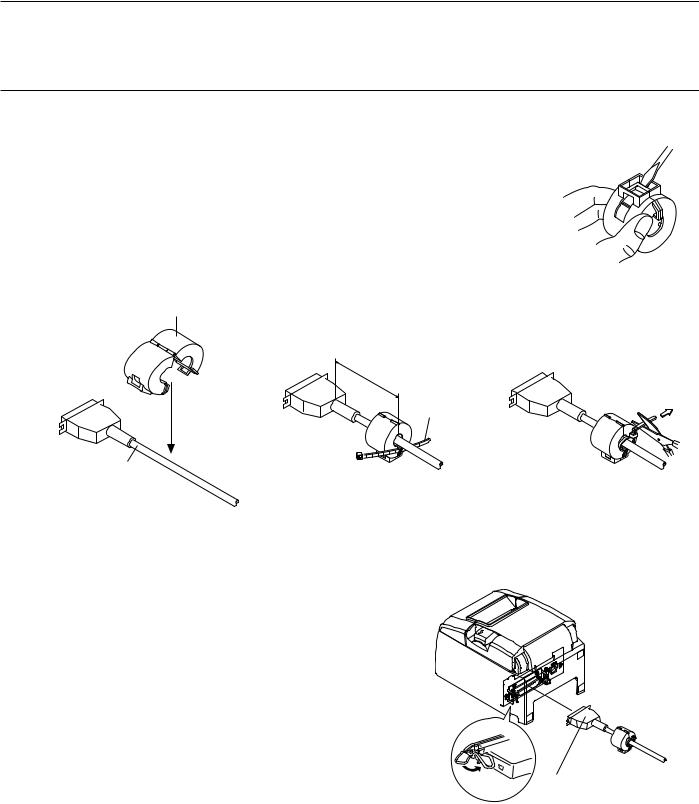
3-2-1. Parallel Interface Cable
(1) Make sure the printer is turn off.
(2) Affix the ferrite core onto the cable as shown in the illustration.
(3) Pass the fastener through the ferrite core.
(4) Loop the fastener around the cable and lock it. Use scissors to cut off any excess.
Ferrite core
5 cm (maximum)
Fastener
Interface cable
(5)Connect the interface cable to the connector on the rear panel of the printer.
(6)Fasten the connector clasps.
Parallel interface cable
– 5 –

3-2-2. RS-232C Interface Cable
(1) Make sure the printer is turn off.
 CAUTION
Before connecting/disconnecting the interface cable, make sure that power to the printer and all the devices connected to the printer is turned off. Also make sure the power cable plug is disconnected from the AC outlet.
(2)Connect the interface cable to the connector on the rear panel of the printer.
(3)Tighten the connector screws.
RS-232C interface cable
3-2-3. USB Interface Cable
Affix the ferrite core onto the USB cable as shown in the illustration below and make sure to pass the cable through the cable support as shown in the illustration.
 4 cm (maximum)
– 6 –
3-2-4. Connecting Ethernet Cable
If a ferrite core is included, install the ferrite core onto the Ethernet cable according to the following procedure to prevent electrical noise.
If a ferrite core is not included, perform steps (1) and (5) only.
When using an Ethernet cable that is 10 m or less, shielded cable is recommended.
(1)Make sure the printer is turned off.
(2)Install the ferrite core onto the ethernet cable as shown in the illustration below.
(3) Pass the fastener through the ferrite core.
(4) Loop the fastener around the cable and lock it. Use scissors to cut off any excess.
10 cm
(maximum)
Ethernet cable
Ferrite core
Fastener
(5)Connect the interface cable to the connector on the rear panel of the printer.
Ethernet interface board |
Ethernet interface board |
|
IFBD-HE05 |
||
IFBD-HE07 |
||
|
Link disconnection detection feature
The Ethernet interface model is equipped with a link disconnection detection feature. If the printer is turned on when an Ethernet cable is not connected to it, the POWER and ERROR lamps are simultaneously turned on and off at 2-second intervals to indicate the disconnection. Be sure to connect the Ethernet cable from a PC or hub to the printer, and then turn the printer on.
– 7 –

3-3. Installing the Printer Software
Here is the procedure for installing the printer driver and utility software, which are stored on the supplied CD-ROM.
The procedure applies to the Windows operating systems shown below.
•Windows XP (SP2 or later)
•Windows Vista
• Windows 7
(1) Turn ON the power to your PC to start Windows.
(2) InsertthesuppliedCD-ROM(DriversandUtilities)intothe
CD-ROM drive.
(3) Follow the instructions that appear on the screen.
(4) The dialog shown in the illustration indicates that the pro- cedure has been completed.
Click “Finish”.
The dialog that appears on the screen varies with your system. This completes the installation of
the printer software. A message will appear, prompting you to restart. Restart Windows.
.
– 8 –
3-4. Connecting the Optional AC Adapter
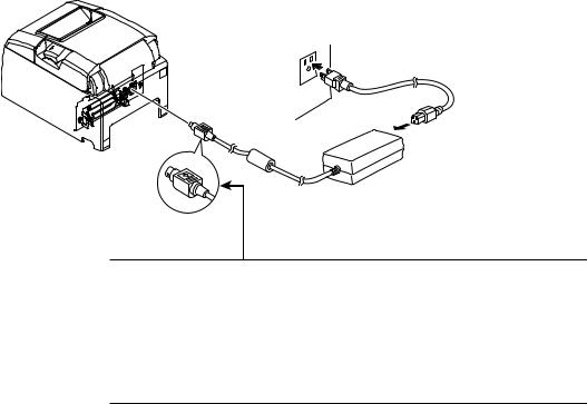
Note: Before connecting/disconnecting the AC adapter, make sure that power to the printer and all the devices connected to the printer is turned off. Also make sure the power cable plug is disconnected from the AC outlet.
(1)Connect the AC adapter to the power cable.
Note: Use only the standard AC adapter and power cable.
(2)Connect AC adapter to the connector on the printer.
(3)Insert the power cable plug into an AC outlet.
 CAUTION
When disconnecting the cable, take hold of the cable connector to pull it out. Releasing the lock makes it easy to disconnect the connector.
Pulling the cable excessively could cause damage to the connector.
– 9 –
3-5. Turning Power On
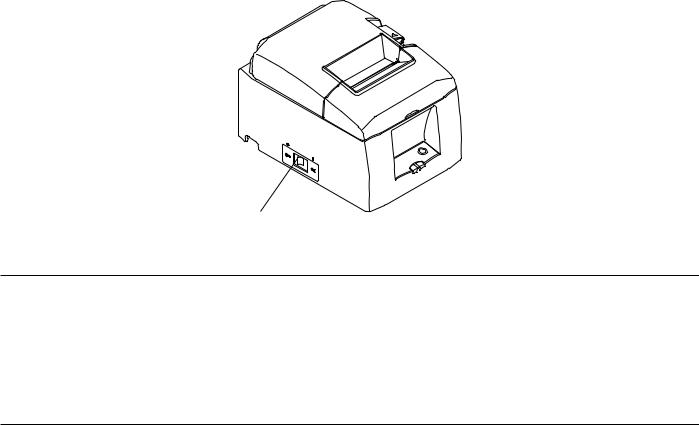
Make sure that the Power cord has been connected as described in 3-4.
Turn ON the power switch located on the front of the printer.
The POWER lamp on the control panel will light up.
Power switch
 CAUTION
We recommend that you unplug the printer from the power outlet whenever you do not plan to use it for long periods. Because of this, you should locate the printer so that the power outlet it is plugged into is nearby and easy to access.
When an Switch blind is affixed to the printer above the power switch, the ON/OFF marks of the power switch may be hidden. If this occurs, remove the power cord from the outlet to turn the printer OFF.
– 10 –

3-6. Connecting to a Peripheral Unit
You can connect a peripheral unit to the printer using a modular plug. See “Modular plug” on page 50 for details about the type of modular plug that is required. Note that this printer does not come with a modular plug or wire, so it is up to you to obtain one that suits your needs.
 CAUTION
Make sure that the printer is turned off and unplugged from the AC outlet and that the computer is turned off before making connections.
Connect the peripheral drive cable to the connector on the rear panel of the printer.
 CAUTION
Do not connect a telephone line into the peripheral drive connector. Failure to observe this may result in damage to the printer.
Also, for safety purposes, do not connect wiring to the external drive connector if there is a chance it may carry peripheral voltage.
– 11 –
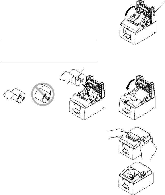
3-7. Loading the Paper Roll
3-7-1. Using 79.5 mm Width Paper Roll
Be sure to use roll paper that matches the printer’s specification.
When using a paper roll with an 57.5 mm width, install the paper roll holder as described on the following page.
1)Push the cover open lever, and open the printer cover.
2)While observing the direction of the roll, set the paper roll into the hollow, and pull on the leading edge of the paper toward you.
 CAUTION
Do not pull out the end of the paper diagonally, as it will cause the paper to become jammed or skewed.
Cover open lever
Paper roll
3) Push down both sides of the printer cover to
close.
Note: Makesurethattheprintercoverissecurely closed.
4) Tear Bar Model:
Tear off the paper as shown.
Auto Cutter Model:
If the printer cover is closed after turning on the power, the cutter operates automatically and the front end of the paper is cut.
Tear Bar Model
– 12 –

3-7-2. Using 57.5 mm Width Paper Roll
When using a paper roll with 57.5 mm width, install the supplied paper guide on the printer.
To change the effective print width (roll paper width), change the setting at memory switch configuration Utility. For details on the setting of the memory switches, refer to the software manual located in the “Documents” folders on the CD-ROM.
1 Insert the paper guide along the groove in the unit as shown.
Paper Guide
2 Insert the paper guide by pushing the area marked “A” down until it clicks into place.
Note: After using a paper roll with a width of 57.5 mm, do not change to a paper roll with a width of 79.5. (This is because the printer head has deteriorated as a result of a portion of the head having been in direct contact with the platen.)
– 13 –

Caution Symbol
These labels are located near the thermal print head.
Because the thermal print head is hot immediately after printing, do not touch it. Static electricity can damage the thermal print head. To protect the thermal print head from static electricity, do not touch it.
This symbol is placed near the cutter.
Never touch the cutter blade, as you could injure your fingers.
This symbol is placed near the peripheral drive connector.
Do not connect this to a telephone.
 WARNING
1)Do not touch the cutter blade.
•There is a cutter inside the paper outlet slot. Not only should you not put your hand in the paper outlet slot while printing is in progress, never put your hand into the outlet even when printing is not in progress.
•The printer cover can be opened when replacing the paper. However, since the cutter blade is on the inside of the printer cover, be careful not to place your face or hands too close to the cutter blade.
2)During and immediately after printing, the area around the thermal head is very hot. Do not touch it, as you could be burned.
 CAUTION
1)Do not operate the cover open lever while pressing on the printer cover with your hand.
2)Do not push the cover open lever and open the printer cover when printing is in progress or when the auto cutter is operating.
3)Do not push out paper while the printer cover is closed.
4)The heating element and the driver IC of the thermal head are easily damaged. Do not touch them with metal objects, sandpaper, etc.
5)Printing quality may suffer if the thermal head heating element becomes soiled by being touched with your hands. Do not touch the thermal head heating element.
6)There is a risk of damage to the driver IC of the thermal head from static electricity. Never directly touch the IC.
7)The printing quality and working life of the thermal head cannot be guaranteed if any paper other than that recommended is used. In particular, paper containing
[Na+, K+, C1-] may drastically reduce the working life of the thermal head. Please exercise caution.
8)Do not operate the printer if there is moisture on the front surface of the head from condensation, etc.
–14 –
Loading...