

Page 1

THERMAL PRINTER
TSP400
INSTALLATION MANUAL
GUIDE D’INSTALLATION
AUFSTELLANLEITUNG
MANUALE DI INSTALLAZIONE
Page 2

Page 3

TABLE OF CONTENTS
1. UNPACKING AND INSPECTION......................................................1
1-1. Unpacking ....................................................................................1
1-2. Handling Notes ............................................................................1
2. PARTS IDENTIFICATION AND NOMENCLATURE ......................2
3. FERRITE CORE INSTALLATION
*EUROPE ONLY ..................................3
Installation of the interface cable ferrite core......................................4
Installation of the peripheral unit cable ferrite core ............................4
4. CONNECTING THE INTERFACE CABLE ....................................... 5
4-1. RS-232C or RS-422A Serial interface .........................................5
4-2. Centronics-type Parallel interface............................................... 5
APPENDIX .............................................................................................24
Page 4
– 1 –
ENGLISH
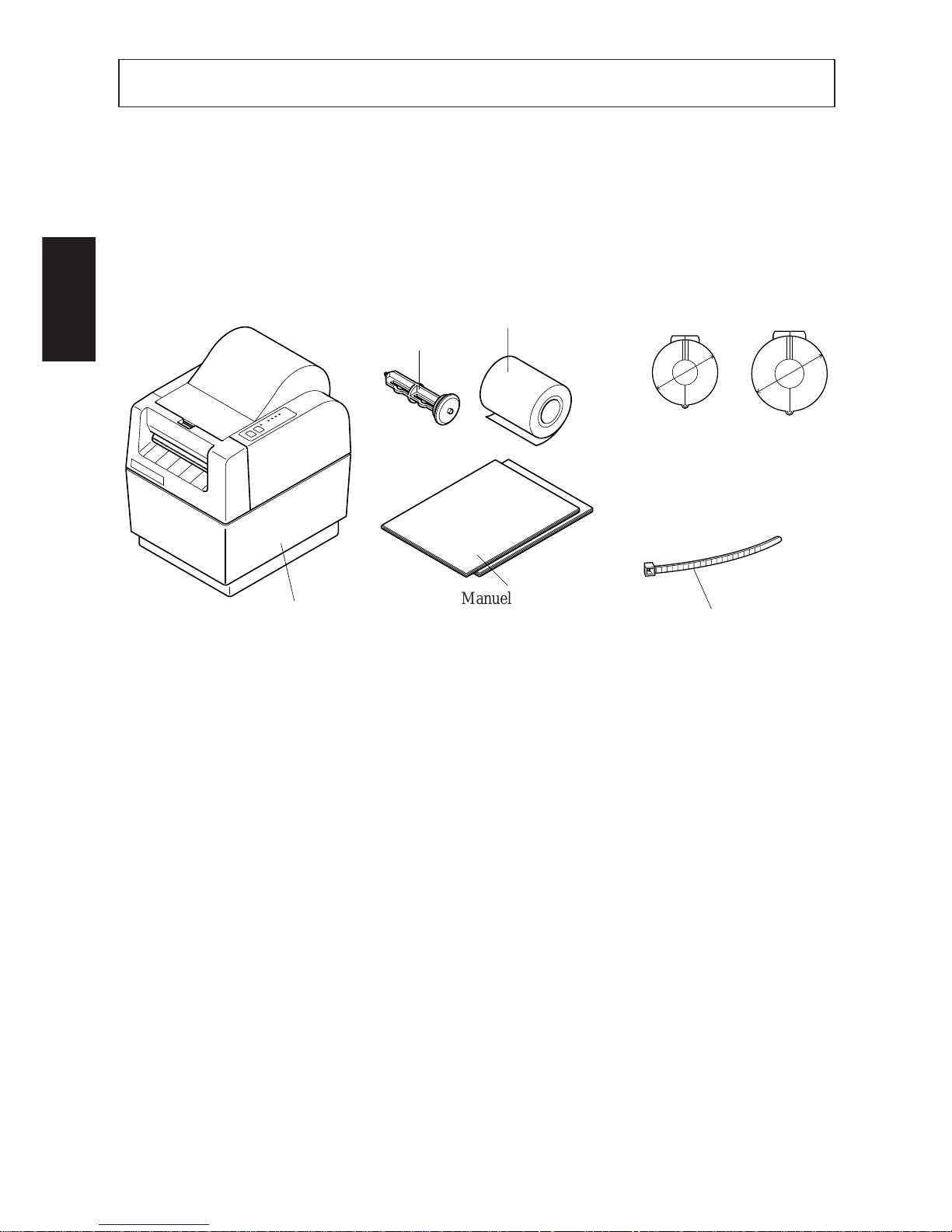
1. UNPACKING AND INSPECTION
1-1. Unpacking
Check each item in the box against Figure 1-1 to make sure that you have
everything (there should be five items).
If any of these items are missing, contact your supplier.
Fig. 1-1
1-2. Handling Notes
Before you start setting up your printer, make sure that you have a suitable place
in which to locate it. By “a suitable place”, we mean:
• Close to an easily accessible socket-outlet.
• A firm, level surface which is fairly vibration-free
• Away from excessive heat (such as direct sunlight, heaters, etc)
• Away from excessive humidity
• Away from excessive dust
• With access to a steady power supply that is not subject to power surges. For
example, do not connect the printer to the same circuit as a large, noiseproducing appliance such as a refrigerator or an air conditioner.
NOTE: Make sure that the line voltage is the voltage specified on the printer’s
identification plate.
Ø24mm
Ø28mm
Printer
Paper-roll shaft
Sample paper roll
User’s manual
Installation Manual
fastener
(E.U. only)
Ferrite core for
interface cable
(E.U. only)
Ferrite core
for peripheral
unit cable
(E.U. only)
Page 5

– 2 –
ENGLISH
2. PARTS IDENTIFICATION AND NOMENCLATURE
To get acquainted with the printer’s components and capabilities, refer to
Figure 2-1.
Fig. 2-1
Printer cover
Protects the print head and
other internal components of
your printer.
Control panel
Indicates printer status
and makes control of
printer functions simple
and convenient.
Automatic paper cutter
(Controlled by command)
(TSP442)
POWER
HEAD UP
NO PAPER
ERROR
ON LINE
FEED
O
N
O
FF
ON
OFF
Power switch
Switches power on or off.
Connector cover
Interface connector
Connects the computer to the printer.
Peripheral drive connector
Only connects to peripheral units
such as each drawers, etc.
Release bar
Opens and closes the print head unit which holds
the paper against the platen.
(TSP412)
Page 6
– 3 –
ENGLISH
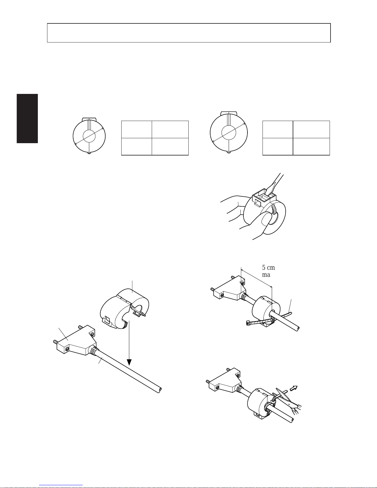
3. FERRITE CORE INSTALLATION *EUROPE ONLY
NOTE: Take special care when following the procedures listed below.
■ Two ferrite core noise filters, large and small, come packed with the printer.
The small noise filter is for the RS232C serial interface cable, while the larger
one is for the cable of peripheral units.
Fig. 3-4
Fig. 3-3
Fig. 3-1
Pass fastener through ferrite core.
Pass fastener around cable and lock it.
Cut off excess with scissors.
Product
Code
Model
Name
09990723
Ferrite Core
TFC-23-11-14
Product
Code
Model
Name
09990728
Ferrite Core
TFC-20-10-10
For Interface Cable For Peripheral Unit Cable
Ø28mm
Ø24mm
■ The ferrite cores are packed so they
are open, as shown in Fig. 3-2. If you
find that a ferrite core is not open, use
a pointed object to pry the plastic lock
of the ferrite core apart (Fig. 3-1).
When you do, take care not to damage
the ferrite core or the plastic lock.
5cm
maximum
Fastener
Pull and cut
Small ferrite Core(24mm diameter)
Interface
Cable
Fig. 3-2
Page 7
– 4 –
ENGLISH
Installation of the interface cable ferrite core
■ Clamp the small ferrite core onto the interface cable as shown in Fig. 3-2. Take
care to avoid damaging the interface cable when installing the ferrite core. The
ferrite core should be anchored firmly in place with the fastener that comes
with it, as shown in Fig.3-3 and 3-4.
Installation of the peripheral unit cable ferrite core
■ Clamp the large ferrite core onto the cable of the interface unit using the same
procedure as you do for the interface cable ferrite core. With the peripheral unit
cable ferrite core, however, you have to loop the cable as shown in Fig. 3-5.
Fig. 3-5
Ground wire
One loop
Large ferrite core
(28mm diameter)
5cm or less
Page 8
– 5 –
ENGLISH
4. CONNECTING THE INTERFACE CABLE
4-1. RS-232C or RS-422A Serial interface
Follow the procedures below to connect the interface cable:
Fig. 4-1
1 Switch off the power to the printer
and computer.
2 Insert the interface cable into the
connector. (Be sure that the cable is
oriented correctly before inserting
it.)
3 Fasten the right and left screws to
fix them in place on the connector.
4 Connect the other end of the inter-
face cable to your computer.
Interface cable
Interface connector
NOTE: The data transfer conditions between the computer and the printer must
be made compatible with the DIP switch settings on the printer. (Refer
to “APPENDIX”.)
4-2. Centronics-type Parallel interface
1 Switch off the power to the printer
and computer.
2 Insert the interface cable into the
connector. (Be sure that the cable is
oriented correctly before inserting
it.)
3 Fasten the connector clasps.
4 Connect the other end of the inter-
face cable to your computer.
Fig. 4-2
Page 9

TABLE DES MATIERES
1. DEBALLAGE ET INSPECTION.......................................................7
1-1. Déballage .....................................................................................7
1-2. Remarques sur la manipulation....................................................7
2. IDENTIFICATION DES PIECES ET NOMENCLATURE ...............8
3. INSTALLATION DU TORE DE FERRITE
*EUROPE UNIQUEMENT ......9
Installation du tore de ferrite de câble d’interface.............................10
Installation du tore de ferrite de câble de périphérique .....................10
4. RACCORDEMENT DU CÂBLE D’INTERFACE ...........................11
4-1. Interface série RS-232C ou RS-422A........................................11
4-2. Interface parallèle type Centronics ............................................11
APPENDICE ...........................................................................................24
L’appendice n’est pas traduit.
Page 10
– 7 –
FRANÇAIS
1. DEBALLAGE ET INSPECTION
1-1. Déballage
Vérifier chaque pièce de la boîte en se référant à la Figure 1 afin de s’assurer qu’on
a bien tout reçu (il doit y avoir cinq pièces).
En cas d’absence d’une de ces pièces, contacter le fournisseur.
Fig. 1-1
1-2. Remarques sur la manipulation
Avant de commencer l’installation de l’imprimante, s’assurer qu’on dispose bien
d’un endroit approprié pour la mettre. Un “endroit approprié” doit satisfaire aux
conditions suivantes:
• A proximité d’une prise d’accès facile
• Surface ferme et à niveau pratiquement sans aucunes vibrations
• A distance de toute chaleur excessive (par exemple lumière du soleil directe,
radiateurs etc.)
• A distance de toute humidité excessive
• A distance de poussière excessive
• Accès à une source d’alimentation constante ne subissant pas de pointes
d’alimentation. Ainsi, par exemple, il ne faut pas relier l’imprimante au même
circuit qu’un appareil important bruyant du genre réfrigérateur ou climatiseur.
REMARQUE: S’assurer que la tension de ligne correspond à la tension indiquée
sur la plaque signalétique de l’imprimante.
Ø24mm
Ø28mm
Manuel d’utilisation
Manuel d’installation
Attache
(Europe uniquement)
Tore de ferrite de
câble d’interface
(Europe
uniquement)
Tore de ferrite
de câble de
périphérique
(Europe
uniquement)
Rouleau de papier échantillon
Arbre du rouleau
de papier
Imprimante
Page 11
– 8 –
FRANÇAIS
Automatic paper cutter
(Controlled by command)
(TSP442)
2. IDENTIFICATION DES PIECES ET NOMENCLATURE
Se référer à la Figure 2-1 pour se familiariser avec les composants et capacités de
l’imprimante.
Fig. 2-1
O
N
O
FF
ON
OFF
Couvercle du connecteur
Connecteur d’interface
Relie l’ordinateur à l’imprimante
Barre de déclenchement
Ouvre et ferme la tête d’impression qui retient le
papier contre le cylindre.
Couvercle d’imprimante
Protège la tête d’impression ainsi
que d’autres composants internes
de l’imprimante.
POWER
HEAD UP
NO PAPER
ERROR
ON LINE
FEED
(TSP412)
Couteau de papier
automatique
(pilotage par commande)
Tableau de commande
Indique l’état de l’imprimante et
simplifie les fonctions de
commande de l’imprimante tout en
facilitant leur exécution.
Interrupteur d’alimentation
Connecte ou coupe l’alimentation
Connecteur d’entraînement de
périphérique
Connexion uniquement à des
périphériques du genre caisses
enregistreuses etc.
Page 12
– 9 –
FRANÇAIS
3. INST ALLATION DU TORE DE FERRITE *EUROPE UNIQUEMENT
REMARQUE:Prendre des précautions spéciales en suivant les procédures
indiquées ci-dessous:
■ Deux filtres antibruit à tore de ferrite, un grand et un petit sont emballés avec
l’imprimante. Le petit filtre antibruit est prévu pour le câble d’interface série
RS232C et le grand doit être utilisé pour le câble de périphérique.
Fig. 3-4
Faire passer l’attache autour du câble et
la bloquer. Couper toute partie qui dépasse avec des ciseaux.
Pull and cut
Tirer et couper
■ Les tores de ferrite sont livrés ouverts
comme indiqué à la Fig. 3-2. Si un tore
de ferrite n’est pas ouvert, utiliser un
objet pointu pour forcer le verrouillage
en plastique du tore de ferrite (Fig.
3.1). Lorsque c’est le cas, prendre
soin de ne pas endommager le tore de
ferrite ni le verrouillage en plastique.
Fig. 3-1
Code du
produit
Nom du
modèle
09990723
Tore de ferrite
TFC-23-11-14
Code du
produit
Nom du
modèle
09990728
Tore de ferrite
TFC-20-10-10
Pour le câble d’interface Pour le câble de périphérique
Ø28mm
Ø24mm
Small ferrite Core(24mm diameter)
Interface
Cable
Fig. 3-2
Petit tore de ferrite (diamètre 24 mm)
Interface
Câble
Faire passer l’attache par le tore de ferrite
5cm
maximum
Fastener
5 cm
maximum
Attache
Fig. 3-3
Page 13

– 10 –
FRANÇAIS
Installation du tore de ferrite de câble d’interface
■ Serrer le petit tore de ferrite au câble d’interface de la manière indiquée à la Fig.
3-2. Prendre les précautions d’usage pour éviter d’endommager le câble
d’interface lors de l’installation du tore de ferrite. Il faut bien immobiliser le
tore de ferrite au moyen de l’attache fournie, comme indiqué à la Fig. 3-3 et à
la Fig. 3-4.
Installation du tore de ferrite de câble de périphérique
■ Serrer le grand tore de ferrite au câble d’interface en suivant la même procédure
que celle du tore de ferrite du câble d’interface. Dans le cas du tore de ferrite
du câble de périphérique, il faut toutefois faire une boucle avec le câble de la
manière indiquée à la Fig. 3-5.
Fig. 3-5
Ground wire
One loop
Large ferrite core
(28mm diameter)
5cm or less
5 cm ou moins
Grand tore de ferrite
(diamètre 28 mm)
Fil à la terre
Une seule boucle
Page 14

– 11 –
FRANÇAIS
4. Raccordement du câble d’interface
4-1. Interface série RS-232C ou RS-422A
Suivre les procédures indiquées ci-dessous pour relier le câble d’interface
Fig. 4-1
1 Couper l’alimentation à l’impri-
mante et à l’ordinateur.
2 Insérer le câble d’interface dans le
connecteur. (S’assurer que le câble
est orienté correctement avant de
l’insérer).
3 Serrer les vis droite et gauche pour
les immobiliser sur le connecteur.
4 Relier l’autre extrémité du câble
d’interface à l’ordinateur.
Interface cable
Interface connector
REMARQUE:Rendre compatibles les conditions de transfert de données entre
l’ordinateur et l’imprimante en réglant les microrupteurs de
l’imprimante en conséquence. (Se référer à “ANNEXE”).
4-2. Interface parallèle type Centronics
1 Couper l’alimentation à l’impri-
mante et à l’ordinateur.
2 Insérer le câble d’interface dans le
connecteur. (S’assurer que le câble
est orienté correctement avant de
l’insérer).
3 Fermer les attaches du connecteur.
4 Relier l’autre extrémité du câble
d’interface à l’ordinateur.
Câble d’interface
Connecteur d’interface
Fig. 4-2
Page 15

INHALTSVERZEICHNIS
1. AUSPACKEN UND KONTROLLE ................................................13
1-1. Auspacken..................................................................................13
1-2. Hinweise.....................................................................................13
2.
FUNKTION UND BEZEICHNUNG DER EINZELNEN BAUTEILE ..
14
3. INSTALLATION DER FERRITKERNE
*NUR EUROPA ..................... 15
Installation des Ferritkerns für das Schnittstellenkabel.....................16
Installation des Ferritkerns für das Peripheriegerätekabel ................16
4. ANSCHLUSS DES SCHNITTSTELLENKABELS ........................17
4-1. Serielle Schnittstellen RS-232C oder RS-422A.........................17
4-2. Parallele Centronics-Schnittstelle ..............................................17
ANHANG................................................................................................24
Der Anhang erscheint nur im englischen Teil dieser Bedienungsanleitung
Page 16

– 13 –
DEUTSCH
1. AUSPACKEN UND KONTROLLE
1-1. Auspacken
Überprüfen Sie an Hand von Abbildung 1 die Teile in der Verpackung, und stellen
Sie sicher, daß alle nötigen Positionen geliefert wurden; es sollten fünf sein.
Falls eines der Teile fehlen sollte, wenden Sie sich bitte an Ihren Händler.
Abb. 1-1
1-2. Hinweise
Wählen Sie für die Aufstellung Ihres Druckers zunächst einen geeigneten Platz
aus. Er sollte folgende Merkmale aufweisen:
• Er sollte nahe einer leicht zugänglichen Netzsteckdose sein.
• Er sollte eine stabile, ebene und erschütterungsfreie Oberfläche haben.
• Er sollte nicht übermäßiger Hitze ausgesetzt sein (wie direktem Sonnenlicht,
einer Heizung usw.).
• In der Druckerumgebung sollte keine übermäßige Luftfeuchtigkeit herrschen.
• Sie sollte nicht übermäßig staubig sein.
• Die Stromversorgung sollte stabil und nicht anfällig für Störungen sein. Sie
sollten den Drucker zum Beispiel nicht an einem Stromkreis zusammen mit
großen, eventuell Störungen verursachenden Geräten wie Kühlschrank oder
Klimaanlage betreiben.
HINWEIS: Stellen Sie sicher, daß die Spannung Ihres Stromnetzes der Betriebs-
spannung entspricht, die auf dem Typenschild des Druckers angegeben ist.
Bedienungsanleitung
Aufstellanleitung
Kabelbinder
(nur EU)
Ferritkern für das
Schnittstellenkabel
(nur EU)
Ferritkern für
Peripheriege–
rätekabel
(nur EU)
Papierrolle
Drucker
Achse für die
Papierrolle
Ø24mm
Ø28mm
Page 17

– 14 –
DEUTSCH
2. FUNKTION UND BEZEICHNUNG DER EINZELNEN BAUTEILE
Machen Sie sich in Abbildung 2-1 mit den Bestandteilen des Druckers und seinen
Funktionen vertraut.
Abb. 2-1
Entriegelungshebel
Mit ihm wird die Druckkopfeinheit entlastet und
angepreßt, mit der das Papier an die Walze gedrückt wird.
Druckerklappe
Sie schützt den Druckkopf und
andere Bauteile im Inneres Ihres
Druckers.
Automatic paper cutter
(Controlled by command)
(TSP442)
POWER
HEAD UP
NO PAPER
ERROR
ON LINE
FEED
(TSP412)
Automatischer
Papierschneider
(befehlsgesteuert)
Bedienfeld
Es zeigt den Druckerstatus an, und
mit ihm lassen sich die
Druckerfunktionen bequem und
einfach steuern.
O
N
O
FF
ON
OFF
Buchse für Peripheriegeräte
Sie dient zum Anschluß von
Peripheriegeräten wie etwa Geldladen,
etc.
Schnittstellenbuchse
An ihr wird der Computer an den Drucker
angeschlossen.
Abdeckung für die
Schnittstellenbuchse
Netzschalter
Mit ihm wird das Gerät an- und
ausgeschaltet.
Page 18

– 15 –
DEUTSCH
5cm
maximum
Fastener
3. INSTALLATION DER FERRITKERNE *NUR EUROPA
HINWEIS: Beachten Sie die folgenden Schritte besonders sorgfältig.
■ Zwei Ferritkerne zum Filtern von Störungen – ein großer und ein kleiner –
werden mit dem Drucker geliefert. Der kleine Entstörungsfilter findet am
Kabel für die serielle RS232C-Schnittstelle Verwendung, das große am Kabel
für Peripheriegeräte.
Abb. 3-4
■ Die Ferritkerne werden in der offenen
Stellung geliefert, siehe Abbildung 3-
2. Sollte ein Ferritkern nicht offen
sein, öffnen Sie den Plastikverschluß
des Ferritkerns mit einem spitzen Gegenstand (Abbildung 3-1). Achten Sie
dabei darauf, daß Sie weder Ferritkern
noch Plastikverschluß beschädigen.
Abb. 3-1
Produktnummer
09990723
Ferritkern
TFC-23-11-14
Produkt-
nummer
09990728
Ferritkern
TFC-20-10-10
für das Schnittstellenkabel für das Peripheriegerätekabel
Ø28mm
Ø24mm
Small ferrite Core(24mm diameter)
Interface
Cable
Abb. 3-2
kleiner Ferritkern (24 mm Durchmesser)
Stecker
Kabel
Abb. 3-3
Modell Modell
Führen Sie den Kabelbinder durch die
Öse am Ferritkern.
5 cm
Maximalabstand
Kabelbinder
Pull and cut
Straffziehen und
abschneiden
Führen Sie den Kabelbinder um das
Kabel, und ziehen Sie ihn fest. Schneiden Sie das überstehende Ende mit einer
Schere ab.
Page 19

– 16 –
DEUTSCH
Installation des Ferritkerns für das Schnittstellenkabel
■ Klemmen Sie den kleinen Ferritkern auf das Schnittstellenkabel, siehe Abbil-
dung 3-2. Achten Sie darauf, daß bei der Installation des Ferritkerns das Kabel
nicht beschädigt wird. Der Ferritkern sollte mit dem mitgelieferten Kabelbinder
sicher an seinem Platz befestigt werden. Siehe Abbildungen 3-3 und 3-4.
Installation des Ferritkerns für das Peripheriegerätekabel
■ Klemmen Sie den großen Ferritkern auf das Kabel für die Peripheriegeräte.
Gehen Sie dabei genauso vor wie oben beim Schnittstellenkabel beschrieben.
Bei diesem Ferritkern allerdings müssen Sie das Kabel in einer Schlaufe laufen
lassen, wie in Abbildung 3-5 gezeigt.
Abb. 3-5
Ground wire
One loop
Large ferrite core
(28mm diameter)
5cm or less
5 cm oder weniger
großer Ferritkern
(28 mm Durchmesser)
Massekabel
eine Schlaufe
Page 20

– 17 –
DEUTSCH
4. ANSCHLUSS DES SCHNITTSTELLENKABELS
4-1. Serielle Schnittstellen RS-232C oder RS-422A
Gehen Sie zum Anschluß des Schnittstellenkabels vor wie unten beschrieben.
Abb. 4-1
1 Schalten Sie Drucker und Compu-
ter aus.
2 Stecken Sie das Schnittstellenkabel
in die Buchse. (Vergewissern Sie
sich, daß das Kabel korrekt ausgerichtet ist, bevor Sie den Stecker
einstecken.)
3 Ziehen Sie die beiden Schrauben links
und rechts fest, so daß der Stecker
sicher an der Buchse befestigt ist.
4 Verbinden Sie das andere Ende des
Kabels mit Ihrem Computer.
Interface cable
Interface connector
Buchse
Schnittstellenkabel
HINWEIS: Die Datenübertragungsparameter von Computer und Drucker müs-
sen übereinstimmen. Sie werden mit den DIP-Schaltern des Drukkers eingestellt (siehe »Anhang«).
4-2. Parallele Centronics-Schnittstelle
1 Schalten Sie Drucker und Compu-
ter aus.
2 Stecken Sie das Schnittstellenkabel
in die Buchse. (Vergewissern Sie
sich, daß das Kabel korrekt ausgerichtet ist, bevor Sie den Stecker
einstecken.)
3 Klammern Sie den Stecker an der
Buchse fest.
4 Verbinden Sie das andere Ende des
Kabels mit Ihrem Computer.
Abb. 4-2
Page 21

INDICE
1. APERTURA E CONTROLLO DELLA CONFEZIONE .................19
1-1. Apertura della confezione ..........................................................19
1-2. Avvertenze .................................................................................19
2. IDENTIFICAZIONE E NOMENCLATURA DELLE PARTI ........20
3.
INSTALLAZIONE DEGLI ANELLI DI FERRITE
*SOLO EUROPA ..
21
Installazione dell’anello di ferrite del cavo d’interfaccia ..................22
Installazione dell’anello di ferrite del cavo dell’unità periferica ......22
4. COLLEGAMENTO DEL CAVO D’INTERFACCIA .....................23
4-1. Interfaccia seriale RS-232C o RS-422A ....................................23
4-2. Interfaccia parallela tipo Centronics ..........................................23
APPENDICE ...........................................................................................24
L’Appendice appare solo nella sezione in inglese di questo manuale.
Page 22

– 19 –
ITALIANO
1. APERTURA E CONTROLLO DELLA CONFEZIONE
1-1. Apertura della confezione
Confrontare il contenuto della confezione con i componenti mostrati nella Figura
1-1 per controllare di aver ricevuto tutto (nella scatola dovrebbero esserci cinque
componenti).
Nel caso mancasse qualcuna di queste parti, contattare il fornitore presso cui si
è effettuato l’acquisto.
Fig. 1-1
1-2. A vvertenze
Prima dell’installazione della stampante, assicurarsi di disporre di un luogo
adatto in cui collocarla. Per “luogo adatto”, intendiamo un luogo:
• vicino ad una presa elettrica facilmente accessibile
• su una superficie solida e piana che non subisca vibrazioni
• lontano da fonti di calore eccessivo (come luce diretta del sole, apparecchi di
riscaldamento, ecc.)
• lontano da umidità eccessiva
• lontano da polvere eccessiva
• con la possibilità di accedere ad una fonte di alimentazione elettrica stabile
non soggetta a sbalzi improvvisi di tensione. Ad esempio, non collegare la
stampante sullo stesso circuito elettrico di grossi apparecchi che producono
disturbi come frigoriferi o condizionatori d’aria.
NOTA: Assicurarsi che la tensione del proprio impianto elettrico corrisponda a
quella specificata sulla piastrina di identificazione della stampante.
Manuale di istruzioni
Manuale di installazione
Fascetta di fissaggio
(solo Europa)
Anello di ferrite
per cavo
d’interfaccia
(solo Europa)
Anello di ferrite
per cavo unità
periferica (solo
Europa)
Rotolo di carta campione
Stampante
Asta del
rotolo di carta
Ø24mm
Ø28mm
Page 23

– 20 –
ITALIANO
2. IDENTIFICAZIONE E NOMENCLATURA DELLE PARTI
Esaminare la Figura 2-1 per conoscere i componenti e le funzionalità della
stampante.
Fig. 2-1
Barra di apertura
Serve per aprire e chiudere l’unità della testina di stampa
che mantiene premuta la carta contro il rullo.
Coperchio della stampante
Protegge la testina di stampa e
gli altri componenti interni della
stampante.
Automatic paper cutter
(Controlled by command)
(TSP442)
POWER
HEAD UP
NO PAPER
ERROR
ON LINE
FEED
(TSP412)
Taglierina della carta
automatica
(Controllata tramite comando)
Pannello di controllo
Indica lo stato della stampante e
semplifica il controllo delle
funzioni della stampante.
O
N
O
FF
ON
OFF
Connettore d’interfaccia
Serve per collegare la stampante al computer.
Interruttore di alimentazione
Serve ad accendere e spegnere
la stampante.
Coperchio del
connettore
Connettore unità periferica
Serve per collegare la stampante ad
unità periferiche, come registratori di
cassa, ecc.
Page 24

– 21 –
ITALIANO
3. INSTALLAZIONE DEGLI ANELLI DI FERRITE
*SOLO EUROPA
NOTA: Prestare particolare attenzione durante l’esecuzione delle procedure
indicate di seguito.
■ Insieme alla stampante vengono forniti in dotazione due anelli di ferrite, uno
grande e uno piccolo, da utilizzare come filtri per la soppressione di eventuali
disturbi. Il filtro antidisturbi piccolo va fissato sul cavo d’interfaccia seriale
RS232C, mentre quello grande serve per il cavo di collegamento di unità
periferiche.
Fig. 3-4
5cm
maximum
Fastener
■ Gli anelli di ferrite sono confezionati
aperti, come mostrato in Fig. 3-2. Se si
trova uno degli anelli di ferrite chiuso,
aprirlo utilizzando un oggetto
appuntito per far leva sul dispositivo
di chiusura di plastica dell’anello di
ferrite (Fig. 3-1). Fare attenzione a
non danneggiare il nucleo di ferrite o
il dispositivo di chiusura di plastica.
Abb. 3-1
Fig. 3-3
Far passare la fascetta di fissaggio attraverso l’anello di ferrite.
Distanza
massima 5 cm
Pull and cut
Far passare la fascetta di fissaggio intorno al cavo e bloccarla. Tagliare la parte
in eccesso con delle forbici.
Fascetta di fissaggio
Tirare e tagliare
Small ferrite Core(24mm diameter)
Interface
Cable
Fig. 3-2
Anello di ferrite piccolo (diametro 24 mm)
Interfaccia
Cavo
Codice
prodotto
09990723
Anello di ferrite
TFC-23-11-14
Codice
prodotto
09990728
Anello di ferrite
TFC-20-10-10
Per il cavo d’interfaccia Per il cavo dell’unità periferica
Ø28mm
Ø24mm
Modello Modello
Page 25

– 22 –
ITALIANO
Installazione dell’anello di ferrite del cavo d’interfaccia
■ Fissare l’anello di ferrite piccolo sul cavo d’interfaccia come mostrato in Fig.
3-2, facendo attenzione a non danneggiare il cavo d’interfaccia. L’anello di
ferrite va saldamente bloccato in posizione con la fascetta di fissaggio fornita
in dotazione, come mostrato nelle Fig. 3-3 e 3-4.
Installazione dell’anello di ferrite del cavo dell’unità periferica
■ Fissare l’anello di ferrite grande sul cavo dell’unità periferica eseguendo la
stessa procedura vista per l’anello di ferrite del cavo d’interfaccia. Tuttavia,
quando si applica l’anello di ferrite sul cavo dell’unità periferica, è necessario
fare un cappio al cavo come mostrato in Fig. 3-5.
Fig. 3-5
Ground wire
One loop
Large ferrite core
(28mm diameter)
5cm or less
Distanza di 5 cm o inferiore
Filo di terra
Cappio
Anello di ferrite grande
(diametro 28 mm)
Page 26

– 23 –
ITALIANO
4. COLLEGAMENTO DEL CAVO D’INTERFACCIA
4-1. Interfaccia seriale RS-232C o RS-422A
Per collegare il cavo d’interfaccia, eseguire le procedure indicate di seguito:
1 Spegnere sia la stampante che il
computer.
2 Inserire il cavo d’interfaccia nel
connettore (assicurarsi che il cavo
sia orientato nel senso corretto prima di inserirlo).
3 Stringere le due viti di destra e sini-
stra per fissare il connettore.
4 Collegare l’altra estremità del cavo
d’interfaccia al computer.
Interface cable
Interface connector
Connettore d’interfaccia
Cavo d’interfaccia
Fig. 4-1
NOTA: Le caratteristiche di trasferimento dati tra il computer e la stampante
devono essere rese compatibili attraverso le impostazioni degli interruttori DIP della stampante (vedere l’“APPENDICE”).
4-2. Interfaccia parallela tipo Centronics
1 Spegnere sia la stampante che il
computer.
2 Inserire il cavo d’interfaccia nel
connettore (assicurarsi che il cavo
sia orientato nel senso corretto prima di inserirlo).
3 Bloccare i fermagli del connettore.
4 Collegare l’altra estremità del cavo
d’interfaccia al computer.
Fig. 4-2
Page 27

– 24 –
APPENDIX
APPENDIX
DIP SWITCHES
DIP switches are located on the interface board. The number of switches varies
according to the board, as follows.
Centronics No DIP switches
RS-232C One 8-bit DIP switch
RS-422A One 8-bit DIP switch and one 4-bit DIP switch
8
1
ON OFF
Page 28

– 25 –
APPENDIX
DIP-switch settings
a) DIP switch #1 (RS-232C, RS-422A)
Switch Setting ON OFF
1-1 Baud
1-2 Baud
1-3 Handshaking DTR X-ON/X-OFF
1-4 Data bits 8 bits 7 bits
1-5 Parity type Not used Used
1-6 Parity type Odd Even
1-7 DCI/DC3 Invalid
Valid (RS-232C only)
1-8 When turning power ON * Refer to the table below.
Baud 1-1 1-2
2400BPS OFF OFF
4800BPS OFF ON
9600BPS ON ON
19200BPS ON OFF
Factory settings : ALL ON
* When the printer’s power is ON.
ON OFF
DC1/DC3 valid mode Select Deselect
Adressable mode Deselect Select (RS-422A only)
DC1/DC3 invalid mode Select Select
b) DIP switch #2 (RS-422A only)
■ DIP SW 2 (RS-422A only)
Function
DC1/DC3
Addressable mode *2
DC1/DC3
Switch
invalid mode
#1 #2 #3 #4 #5 #6 #7 #8 #9 #10 #11 #12 #13 #14
valid mode
2-1
ON OFF ON OFF ON OFF ON OFF ON OFF ON OFF ON OFF ON OFF
2-2
ON ON OFF OFF ON ON OFF OFF ON ON OFF OFF ON ON OFF OFF
2-3
ON ON ON ON OFF OFF OFF OFF ON ON ON ON OFF OFF OFF OFF
2-4
ON ON ON ON ON ON ON ON OFF OFF OFF OFF OFF OFF OFF OFF
Page 29

– 26 –
APPENDIX
Print Density Adjustment
Since the sensitivity of different types of heat-sensitive paper varies, you can
adjust the print density by varying the current supplied to the thermal head.
The print density can be adjusted using the variable resistor inside the hole beside
the interface connector on the back of the printer.
1. To adjust the density turn the resistor roughly two times using a small crosshead screwdriver.
2. Turn the resistor to the right (clockwise) for a darker print density or to the left
(counterclockwise) for a lighter density.
NOTE: If the density is increased to a higher level than necessary when printing
on highly sensitive heat-sensitive paper, the dots may be too large and the
print quality may decrease.
Excessively high energy adjustment may reduce head life.
Variable resistor
used to adjust the
print density
Page 30

– 27 –
APPENDIX
Sensor Adjustment
■ Sensor levels are adjusted at the factory. If necessary, you can readjust the
levels as described below.
1) Remove the ROM cover located beneath the paper-roll holding area.
2) Hold down the FEED and ON LINE switches while switching on the power, and
continue to hold them down until you hear a triple beep. (This will take about
five seconds.) When you hear the triple beep, release the buttons to enter
sensor-adjustment mode.
a) Reflective Sensor
• Insert a non-black area of paper into the mechanism’s sensor area.
• Rotate the main PCB’s sensor adjustment knob (VR4) to the point where the
HEAD UP indicator comes on.
b) Paper-Out Sensor
• Insert a non-black area of paper into the mechanism’s sensor area.
• Rotate the main PCB’s sensor adjustment knob (VR3) to the point where the
NO PAPER indicator comes on.
c) Transmissive Sensor
• Insert the backing portion of a label sheet into the mechanism’s transmissive
sensor area. (Insert the backing part only, not the label itself.)
• Adjust the main PCB’s coarse (VR1) and fine (VR2) adjustment knobs to the
point where the ERROR indicator comes on.
NOTE: When inserting paper, be sure to lower the head so that it is close to
its normal fixed position.
Page 31

– 28 –
APPENDIX
EPROM
VR4
Variable Resistances (Sensor Adjustment Knobs)
Main PCB
Interface PCB
VR2
VR3
VR1
Page 32

– 29 –
APPENDIX
Connectors and Signal Names (Serial Interface)
RS-232C Interface
Pin no Signal name
Direction
Function
1 F-GND – Frame ground
2 TXD OUT Outgoing data
3 RXD IN Incoming data
4 RTS OUT Request To Send: The printer sets this signal
to “SPACE” when it is ready to send.
5 CTS IN The host sets this signal to “SPACE” when it
is ready to send. NOTE: The printer does not
monitor this signal.
6 N/C Not used
7 S-GND – Signal ground
8 N/C Not used
9 ~ 10 N/C Not used
11 RCH OUT The printer sets this signal to “SPACE” when
it is ready to receive. This pin outputs the
same signal as pin 20, to which it is con-
nected.
12 N/C Not used
13 S-GND – Signal ground.
14 FAULT OUT The printer sets this signal to “MARK” to
indicate an error condition (machine error, no
paper, etc.).
15
Multi-Printer TXD
OUT Diode gate TXD
16
Multi-Printer DTR
OUT Diode gate DTR
17 ~ 19 N/C Not used
20 DTR OUT Data Terminal Ready: The printer sets this
signal to “SPACE” when it is ready to re-
ceive.
21 ~ 22 N/C Not used
23 ~ 25 N/C Not used
13 1
14
25
Page 33

– 30 –
APPENDIX
These pins carry data from the printer.
These pins carry data to the printer.
The host sets this signal to “SPACE” when it
is ready to send.
NOTE: The printer does not monitor this
signal.
The host sets this signal to “SPACE” when it
is ready to receive.
NOTE: The printer does not monitor this
signal.
The printer sets this signal to “SPACE” when
it is ready to receive.
The printer sets this signal to “SPACE” when
it is ready to receive.
RS-422A Interface
Pin no Signal name
Direction
Function
9 SD(+) OUT
10 SD(–) OUT
17 RD(+) IN
18 RD(–) IN
19 CS(+) IN
23 CS(–) IN
24 RS(+) OUT
25 RS(–) OUT
Interface Connections
Refer to the host computer’s interface specifications for details of how to connect
the interface. The following illustrations show typical connection configurations.
[RS-232C]
1
2
3
4
5
7
14
20
1
2
3
4
5
6
7
8
20
F-GND
TXD
RXD
RTS
CTS
DSR
S-GND
DCD
DTR
F-GND
TXD
RXD
RTS
CTS
S-GND
FAULT
DTR
Printer side IBM PC side
Page 34

– 31 –
APPENDIX
[RS-422A]
17
18
9
10
Twisted pair cable
Printer #n
RD
SD
SD
RD
17
18
9
10
Printer #n+1
RD
SD
Printer side Host side
Signal Name Sample Circuit
InputOutput
DATA 1
DATA 8
STROBE
BUSY
ACK
~
4.7k
Ω
74LS-equivalent
1kΩ
100Ω
1000pF
74LS-equivalent
1.8kΩ
74LS-equivalent
Page 35

– 32 –
APPENDIX
Connectors and Signal Names (Parallel Interface)
(18) (1)
(36) (19)
Conforms to Amphenol
connector 57-30360
(Printer Side)
Page 36

– 33 –
APPENDIX
PAIR RETURN
Pin no Signal name
Direction
Function
1 STROBE IN Strobe pulse for data read. Usually HIGH;
goes LOW to trigger data read.
2-9 DATA 1~8 IN Parallel data lines for eight-bit data. HIGH
is “1”; LOW is “0”.
10 ACK OUT Printer outputs this pulse for approxi-
mately 9µs to indicate that data read is
completed. Printer becomes ready to
receive new data at the moment the ACK
pulse ends.
11 BUSY OUT DC-level signal indicating printer’s current
status. LOW indicates that printer is ready to
receive the next data; HIGH indicates that
printer is unable to receive. The printer holds
this signal “HIGH” during any of the following conditions.
1 While data entry is in progress
2 While printer is offline 3 While error
condition exists
12 PAPER OUT OUT DC-level signal indicating whether printer
has paper. The signal stays LOW while paper
is present; it goes HIGH to indicate that paper
has run out.
13 SELECTED OUT DC-level signal; stays HIGH while printer is
online.
14-15 N/C Not used
16 SIGNAL GND Signal ground
17
CHASSIS GND
Printer-frame ground
18 +5V Outputs +5V (Max. 50mA)
19-30 TWISTED Return pins for various signals. Each pin is
connected to the corresponding signal line by
twisted pair line.
31 RESET IN LOW level causes printer to reset its control
circuitry and return to its initial state.
32 ERROR OUT Goes LOW to indicate that printer is unable to
print.
33 EXT GND Ground terminal for external connection
34-35 N/C Not used
36 – – Fixed “HIGH” at printer side
Page 37

– 34 –
APPENDIX
16
Modular plug MOLEX 90075-0007,
AMP641337 or JAPAN BURNDY B-66-4
Shield
Wire lead
Separated Ground wire
connected to shield (Europe only).
Ground wire
1 turn
Ferrite core
Distance within 5cm.
Peripheral Unit Drive Circuit
A drive circuit for driving peripheral units (such as cash drawers) is featured on
the main logic board of this printer. A modular connector for driving peripheral
units is featured on the output side on the drive circuit. When using this circuit,
connect the cable for the peripheral unit. (Cables must be prepared by the user.)
Note that Page Mode does not support external-device drive commands. Drive
commands are available only in Line Mode.
Use cables which meet the following specifications.
1. Use the modular plug as shown in Figure 17.
2. Separate ground wire is required for Europe only.
3. Use if the printer is to be used in Europe, the Ferrite core and the cable should
be separate, as shown in Figure 18.
CAUTION: DO NOT connect any other plug to the peripheral unit connector.
Cable specifications for peripheral unit.
Separate ground wire and noise filter are required for Europe.
Page 38

– 35 –
APPENDIX
[Drive output 24V, max. 1.0 A]
7824
F.G
TR1
M-GND
TR2
M-GND
TR3
+5V
+24V
R1
R2
6
5
4
3
2
1
L1
L2
R3
4.7kΩ
1/4W
Frame
ground
D1
D2
Peripheral
unit 1
With shield
Peripheral
unit 2
Compulsion
switch
■ Drive circuit
The recommended drive circuit is shown.
NOTES:
1. Peripheral units #1 and #2 cannot be driven simultaneously.
When driving a device continuously, do not use drive duty above 20%.
2. Compulsion switch status is available as status data.
3. Resistance for coils L1 and L2 is not less than 24 ohms.
4. Absolute maximum ratings for diodes D1 and D2 (at Ta=25˚C):
Average rectified current Io = 1A
Maximum forward surge current (60Hz,1-cycle sine wave) I
FSM=40A
5. Absolute maximum rating for transistors TR1 and TR2 (at Ta = 25˚C):
Collector current Ic = 2A
P 1996.1
Page 39

Printed in Japan, 80871025
HEAD OFFICE
STAR MICRONICS CO., LTD.
20-10 Nakayoshida, Shizuoka, 422 Japan
Tel: (054) 263-1115, Telefax: (054) 263-8714
OVERSEAS SUBSIDIARY COMPANIES
STAR MICRONICS AMERICA, INC.
70-D Ethel Road West, Piscataway, NJ 08854 U.S.A
Tel: (908) 572-9512, Telefax: (908) 572-5095,
Telex: 299766 STAR UR
STAR MICRONICS DEUTSCHLAND GMBH
Westerbachstraße 59, D-60489 Frankfurt/Main 90, Germany
Tel: 0697-89990, Telefax: 0697-81006, Telex: 417 5825 STAR D
STAR MICRONICS U.K. LTD.
Star House, Peregrine Business Park, Gomm Road,
High Wycombe, Bucks, HP13 7DL, UK
Tel: 01494-471111, Telefax: 0494-473333
 Loading...