

Page 1

WARNINGS
• Always read tool manual before operating.
• Always wear safety glasses while operating or
while in the vicinity of a tool in operation.
• For testing, always cycle tool away from work
to insure proper ring closure. For safety
reasons, an improperly functioning tool must
not be used. When operating tool, never point
or actuate tool other than into work.
• Operate tool in an unobstructed work area.
• Disconnect air supply prior to maintenance
and/or repair of tool.
• Use clean dry air to maximize efficiency. Do
Not Exceed 100 P.S.I. (7.0 kg/cm sq.)
• Do not use bottled gases such as oxygen,
hydrogen, carbon dioxide, acetylene, etc.
• Tools shall be operated with a fitting or hose
coupling on or near the tool in such a manner
that all compressed air in the tool is discharged
at the time the fitting or hose coupling is
disconnected.
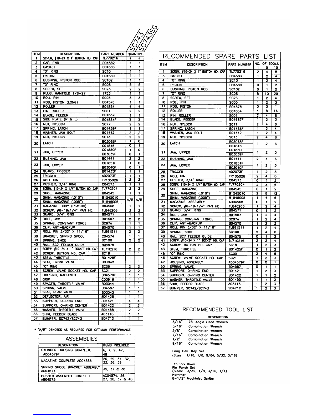
PNEUMATIC C-RING TOOL
SC743 SC743SG
SAFETY INSTRUCTIONS
WARNING:
The employer and/or user must ensure
that proper eye protection is worn. Eye
protection equipment must conform to
the requirements of the American
National Standard Institute, ANSI Z87.1-1989 and
provide frontal and side protection. Eye protection
should be worn by the operator and others in the work
area when loading, operating, or servicing this tool.
Eye protection is required to guard against possible
flying particles and/or debris, which could cause
severe eye injury.
NOTE: Non-side shielded prescription glasses and
faceshields alone do not provide adequate protection.
OPERATION
Always handle tool with care:
• Never engage in horseplay.
• Never pull the trigger unless nose of tool is
directed toward the work.
• Keep others at a safe distance from the tool while
the tool is in operation as actuation occurs,
possibly causing injury. Keep hands and body
away from the jaw mechanism of the tool.
LOADING TOOL
When loading tool:
• Never place a hand or any part of body in jaw
mechanism area of tool.
• Never point tool at anyone.
• Never actuate tool when loading, accidental injury
may occur.
AIR CONSUMPTION
SC7 Series Tools require 3.3 cubic feet per minute
(.093 cubic meters per minute) of free air to operate at
a rate of 100 fasteners per minute, at 100 P.S.I. (7.0
kg/cm sq.).
1 of 6 01/03
Page 2
2 of 6 01/03
Page 3

3 of 6 01/03
Page 4

TO DISASSEMBLE
Jaws, magazine and pusher assembly
1. Remove screw (#28) from magazine and feeder guide rail (#31
and #40).
2. Remove (2) button head screws (#1) from rear of feeder guide
rail.
3. Remove lock nuts, washers and latch spring (#19, #18 and #17)
from jaw bolts (#34).
4. Remove jaw bolts from tool, this allows the magazine and
pusher assemblies, latch (#20) and jaws (#21 and #23) with
jaw bushings (#22) to be removed from the tool.
Feeder blade and rollers
1. Remove button head screw (#42) from trigger guard (#24).
2. Remove (2) socket head cap screws (#41) with lock nuts (#16).
3. Remove side plates, trigger guard, trigger and roll pins (#15,
#24, #25 and #10).
4. Remove (4) rollers, (2) roller pins, feeder blade and feeder
blade shim (#12, #13, #14 and #56).
Piston and Piston Rod
1. Remove the remaining button head screws (#1) from rear of
tool.
2. Remove end cap and end cap gasket (#2 and #3).
3. Slide piston rod (#11) so that the piston end is exposed out of
the housing.
4. Place tool into vise clamping down on flat areas of piston rod
(do not over-tighten so as not to deform feeder blade slot).
5. Apply heat as needed to break down thread lock adhesive on
threaded end of piston rod.
6. Remove piston (#5) with 9/16” open end or adjustable spanner
wrench.
7. Piston rod (#11) and bumper (#57) may now be removed from
front of tool.
8. Remove piston rod o-ring (#7) using machinist scribe from the
clearance hole at the front of tool (side plate mtg. end).
Throttle
1. Remove screw and air deflector parts (#28 and #52).
2. Loosen set screws (#8) on both ends.
3. Remove rear valve seat (#51).
4. Remove throttle spring (#50).
5. Remove front valve seat (#44) and throttle stem (#43) using a
3/16” wrench.
6. Using two 9/64” Allen wrenches, unscrew throttle valve
screws (#46) to remove valve units. Hint: Hold tool so that
the valve is vertical to help prevent loosing parts.
7. One valve screw will remain with other valve parts on throttle
valve spacer (#49), and can be disassembled after removal
from housing.
8. 1/8” NPT plug (#9) is to be removed only during manifold kit
installation.
TO RE-ASSEMBLE
1. Assemble one side of the o-ring support assembly (#46, #55,
#53, #7, #54, #7 and #53) on throttle valve spacer (#49). The
chamfer on both washers (#55) should be installed, with
chamfer side against cap screw head (#46).
2. Hold tool vertically and install o-ring support assembly with
spacer into throttle bore from the top.
3. Holding cap screw with an 9/64” Allen wrench, bring second
o-ring support assembly (mounted on screw (#46)) in from the
opposite side and complete valve assembly. The valve should
have free motion of travel of about 3/32” [.09”(2.3mm)].
4. Insert throttle stem (#43) into front valve seat (#44) and slowly
screw front valve seat with lubricated o-ring (#45) into front of
the valve bore. (See Throttle Valve Adjustment Procedure).
5. Insert valve spring (#50) into the rear of the valve assuring that
the locator is inserted into the hex of the cap screw (#46).
6. Screw rear valve seat (#51) with lubricated o-ring (#45) into
rear of the valve port.
7. Install o-ring (#7) into housing from the front using the piston
rod clearance hole.
8. Install bumper (#57) onto piston rod (#11) so the tabs are at the
threaded end of the piston rod.
9. Slide piston rod (#11) into front of housing. Be careful not to
damage o-ring (#7) when pushing piston rod into housing, use
lubrication.
10. Place o-ring (#4) onto piston (#5).
11. Apply Loctite #242 or equivalent onto threads of piston rod
(#11).
12. Slide piston with o-ring into housing end, aligning piston with
piston rod. Be careful of piston o-ring when inserting piston,
use lubrication on the o-ring.
13. Use 9/16” open end or adjustable spanner wrench to tighten
piston while holding flat areas of piston rod.
14. Mount the end cap (#2) with notch in gasket (#3) properly
aligned to the housing using only two button head screws (#1)
as shown in exploded view.
15. Mount feeder blade, feeder blade shim and two roller pins
(#14, #56 and 13) on piston rod (#11).
16. Place rollers (#12) on the roller pins (#13). Lubrication will
hold the rollers in place while assembling the rest of the tool.
17. Assemble trigger and trigger guard (#25 and #24) to the side
plates with (3) roll pins (#10).
18. Verify that valve stem is still inserted into front valve seat.
19. Slide side plates (#15) with trigger and trigger guard into place
on the housing (slight force may be used to place the side
plates onto the key on housing).
20. Insert (2) socket head cap screws (#41) from magazine side of
tool and install lock nuts (#16).
21. Leave trigger guard loose for adjusting the valve. See Throttle
Valve Adjustment Procedure for proper valve adjustment
instructions.
22. Insert roll pins (#26) into pusher (#27) from both sides.
23. Install pusher onto feeder guide rail (#40) by sliding feeder
guide rail through the spacer between the roll pins and the
pusher body. Make sure that the pusher is in proper
orientation, see parts diagram.
24. Mount constant force spring (#35) onto spring spool bracket
(#38) using roll pin (#37). Make sure that spring is in the
proper orientation, see parts diagram.
25. Install feeder guide rail onto spring spool bracket using roll pin
(#37).
26. Attach the constant force spring (#35) onto pusher (#27) with
button head cap screw (#28) (feed the spring through the large
opening in pusher).
27. Attach feeder guide rail to rear of housing using button head
cap screws (#1).
28. Mount latch (#20) onto side plate (#15) side opposite the
magazine.
29. Install jaw bushings (#22) into jaws (#21 and #23). Lubricate
both jaws and bushings before installing them.
30. Place jaws with bushings between the side plates.
31. Slide magazine assembly into position between spring spool
bracket and side plate. Attach the magazine assembly to the
rear of the feeder guide rail using button head cap screw (#28).
But do not tighten completely.
4 of 6 01/03
Page 5

31. Place (1) .010” magazine shims (#30) under the magazine foot,
between magazine and side plate. Other shims may be added
or subtracted to get the proper drop in the magazine shoe. See
Magazine Adjustment Procedure.
32. Insert jaw bolts (#34) through the spring spool bracket,
magazine, shims, side plate, jaw bushing, side plate, latch
spring (#17) and washers (#18). Secure jaw bolts with nylock
nuts (#19). Do not over tighten jaw bolts, jaws must still pivot
freely.
33. Tighten button head cap screw (#28) at the rear of magazine.
34. After all adjustments to the tool are made, the trigger guard is
secured with button head screw (#42).
INSTALLATION PROCEDURE / ADJUSTMENTS
Magazine
1. Before tightening jaw bolts (#34), insert approximately .010”
of shims.
2. Tighten bolts and check magazine shoe (#29) for proper fit.
3. When shimmed correctly, and with the feeder blade in the
forward position, the shoe should have approximately
.010”(.25mm) float up and down.
4. Cycle tool and check for proper ring closure. If feeder blade
hits rear of shoe, add another shim. Shims (#30) are available
in two thickness’ of .005”(.013mm) and .010”(.25mm).
5. When the tool is completely re-assembled, check to insure that
magazine (#31) is parallel to housing (#47).
Throttle valve
Follow these steps after completing tool assembly in order to
minimize the time and effort required for optimum throttle valve
adjustment:
1. Using the valve stem, slowly screw in the front valve seat
(#44) until it bottoms, then back it out 1-1/2 turns.
2. Do the same with the rear valve seat (#51).
3. Attach an air line and fully depress the trigger. AIR SHOULD
LEAK OUT THE REAR VALVE SEAT. While depressing
the trigger, slowly turn in the rear valve seat (#52) until the air
stops leaking.
4. Release the trigger. AIR SHOULD LEAK OUT OF THE
HANDLE. Place a 3/16 wrench on the trigger valve stem
(#43) and turn the front valve seat (#44) in slowly until the air
stops leaking from the handle.
5. Gently depress the trigger. Air should flow evenly from the
rear exhaust to the handle exhaust.
6. The valve should now be adjusted - test the tool.
7. Tighten the front and rear valve seat locking set screws (#8)
and re-test the tool.
TOOL LEAKS AIR OR IS SLUGGISH
1. If tool is leaking air in the throttle area, see “Throttle Valve
Adjustment” section.
2. Should the tool leak air in both the triggered and rest positions,
a damaged piston o-ring may be the cause. Once the piston oring has been replaced, lubricate with lithium grease.
3. Put a few drops of light oil into the inlet fitting to lubricate the
piston o-ring if tool is running sluggish.
4. If the tool is operating too quickly for the operator, remove
button head cap screw (#28) and replace with set screw, jam
nut and shakeproof washer (part numbers SC25, SC15 and
SC28). The set screw can be used as an air flow control
device.
CONVERTING TO A LEFT HANDED TOOL
1. Remove (2) jaw bolts, nuts, washers and (1) latch spring (#34,
#19, #18, and #17).
2. Remove (4) button head cap screws (#1).
3. Remove magazine assembly and pusher system.
4. Remove latch (#20) and move to other side.
5. Remove jaws (#21 and #23) and replace them back in the
opposite way.
6. Place magazine assembly and pusher system onto other side.
7. Replace latch spring and fasteners.
LUBRICATION
1. The “SC” series Flex-C tools are designed for long, troublefree service with minimal air line lubrication. (If an in-line
lubricator is used, it should be set at the minimum rate of
flow.)
2. Excess oil in the tool will attract dirt, lint, and the adhesive
material used in collating the fasteners, preventing smooth
operation. When lubrication is used, always use a good grade
of 5W non-detergent oil with no additives.
3. When servicing or repairing tool use lithium grease on all
moving parts.
FILTER AND REGULATOR
The air line should always contain a filter and regulator unit to
provide the tool with a constant flow of clean, dry air. If moisture
and contaminates are allowed to enter the tool, the tool’s
serviceable life will be decreased.
TIPS ON EXTENDING TOOL LIFE
The serviceable life of the “SC” series tools can be extended greatly
by using the following guidelines:
1. Always use Stanley Fastening Systems brand fasteners. Never
replace worn or broken parts with anything other than genuine
Stanley Fastening Systems parts. Generic fasteners may
shorten the life of your Flex-C tool and will void the
manufacturer’s warranty.
2. Keep your tool(s) clean and dry. Always use clean, dry air and
never exceed the recommended air pressure.
3. Use of this tool at minimum air pressure required for the work
at hand will greatly extend the life of the tool.
4. Exercise caution not to drop equipment. Tools dropping onto
the floor or ground is a primary reason for parts replacement.
HELPFUL HINTS FOR FIELD SERVICE TOOL JAMS
1. The most common reason for jamming problems in the SC tool
is short cycling. Because of the tool’s valve unit, the trigger
must be pulled completely to the rear to ensure positive
functioning of the valve. If the tool is “short cycled,” the feed
mechanism will return forward prematurely in an attempt to
pick up a second ring. This will most likely cause a jam.
2. If a jam occurs, pull pusher and rings back on magazine. Point
tool away from yourself and others, and cycle tool slowly.
This should force jammed ring(s) out of jaw mechanism.
3. If procedure “2” does not clear the tool, disconnect air, lay
tool on a clean flat surface and remove top jaw bolt and nut,
and pull top jaw and bushing from tool. Jammed rings are now
exposed and may be removed from tool. Remove build up of
dirt, lint, and any other foreign debris and check for worn or
damaged parts. Re-assemble in reverse order.
4. Replace worn or damaged parts to keep tool operating
properly.
5 of 6 01/03
Page 6

SPECIFICATIONS AND TYPES OF MATERIALS AVAILABLE BY PART NUMBER
Part Number Per
Strip #
Per Box # Material Wire
Diameter
Ring I.D. Ring Leg
Opening
Operating Range of Tool
SC743 - SC743SG
RING16G110 110 11,000 Galvanized 0.062 0.80 0.57 3/16 - 11/32 13/32 – 7/16
RING16SS110 110 11,000 Stainless Steel 0.062 0.80 0.57 3/16 - 11/32 13/32 – 7/16
RING16AL110 110 11,000 Aluminum 0.062 0.80 0.57 3/16 - 11/32 13/32 – 7/16
* Please specify “Blunt” or “Sharp” when ordering rings.
RING DOES NOT CLOSE COMPLETELY
1. Check air pressure. Line pressure at the tool should be between 90 and 95 psi (6.3 – 6.7 kg/cm sq.). The tool should never be
operated at pressures exceeding 100 psi (7.0 kg/cm sq.).
2. A 3/8” (9.5 mm) or larger air line should be used with the “SC” Series Tools. Air lines in excess of 100’ (30.5 meters) in length can
cause air volume deficiencies at the tool which will prevent normal operation.
3. Check for foreign debris in the jaw area. This is especially true in the area between the side plates and rollers.
4. The jaws may be worn from extended use. Check the “land” between the receiving grooves of the jaws. If the land is worn
excessively, replacing the jaw(s) is recommended.
5. When the tool is used in corrosive applications, light oil should be applied on a regular basis to the jaw bushings and rollers.
Unlubricated and/or corroded jaw bushings may cause the tool to function poorly.
6. When ring teardrops, the latch is not backing the ring up properly. Replace or reshape latch spring to hold latch against the side
plate. The latch may also need replaced to get proper ring shape.
FEEDING PROBLEMS
1. If rings do not feed smoothly down the magazine, check pusher spring for proper tension. If the magazine is covered with dirt from
field use, clean the magazine and apply a light coating of oil.
2. When rings feed properly on the magazine but do not feed into the jaws without spitting out of the magazine side of the tool, or if
the rings sit in the jaw grooves on an angle, check jaws to insure freedom of movement. With the jaws void of rings, the vertical
movement should be approximately .06” (1.5 mm). The jaw bolt nuts should be snug, but never over-tightened.
3. After considerable use or several jams, the fingers on the pusher may show signs of spreading. This may cause the pusher to “hang
up” on the magazine, with little or no pressure behind the rings. The last few rings in the strip will not feed into the jaw mechanism.
The pusher fingers can be squeezed back into proper position or the pusher should be replaced. NEVER USE UNCOLLATED
RINGS IN THE SC TOOL.
LIMITED WARRANTY
Stanley Fastening Systems warrants to the original retail purchaser that this product is free from defects in material and
workmanship, and agrees to repair or replace, at Stanley Fastening Systems’ option, any defective product within 60 days from
the date of purchase. This warranty is not transferable. It only covers damage resulting from defects in material or workmanship,
and it does not cover conditions or malfunctions resulting from normal wear, neglect, abuse, or accident.
THIS WARRANTY IS IN LIEU OF ALL OTHER EXPRESS WARRANTIES. ANY WARRANTY OF
MERCHANTABILITY OR FITNESS FOR A PARTICULAR PURPOSE IS LIMITED TO THE DURATION OF THIS
WARRANTY. STANLEY FASTENING SYSTEMS SHALL NOT BE LIABLE FOR ANY INCIDENTAL OR
CONSEQUENTIAL DAMAGES.
Some states do not allow limitations on how long an implied warranty lasts, or the exclusion or limitation of incidental or
consequential damages, so the above limitations or exclusions may not apply to you. This warranty gives you specific legal
rights, and you may also have other rights which vary from state to state.
To obtain warranty service, you must return the product at your expense together with the proof of purchase to a Stanley-Bostitch
Regional warranty repair center or you may call us at 1-800-556-6696 or 1-800-832-3080 for the location of additional
authorized warranty service locations in your area.
6 of 6 01/03
 Loading...