

Page 1
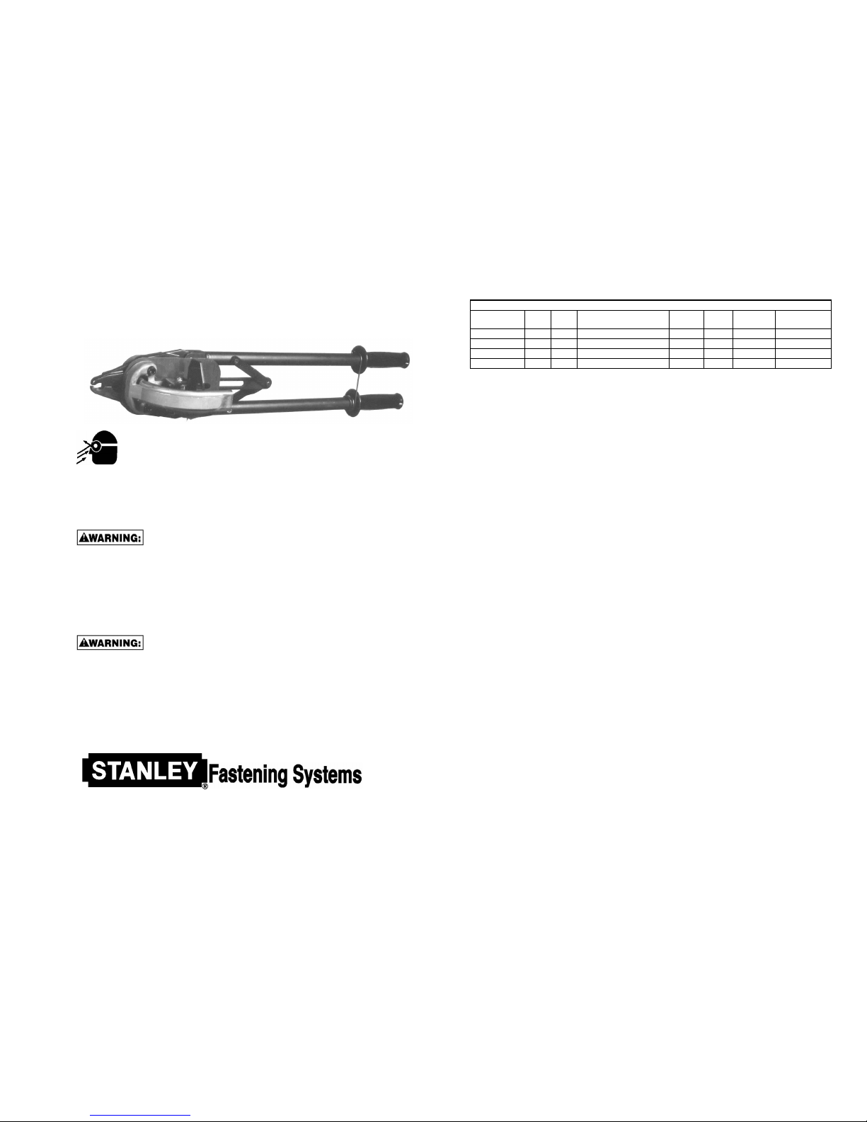
C-RING HAND PLIERS
SC50HP
SAFETY INSTRUCTIONS
WARNING:
The employer and/or user must ensure that proper eye protection is worn. Eye
protection equipment must conform to the requirements of the American National
Standard Institute, ANSI Z87.1-1979 and provide frontal and side protection. Eye
protection should be worn by the operator and others in the work area when loading,
operating, or servicing this tool. Eye protection is required to guard against possible flying particles
and/or debris, which could cause severe eye injury.
NOTE: Non-side shielded prescription glasses and faceshields alone do not provide adequate protection.
OPERATION
Always handle tool with care:
• Never engage in horseplay.
• Never actuate pliers unless nose of tool is directed toward the work.
• Operate tool in an unobstructed work area.
• Keep others at a safe distance from the tool while the tool is in operation as actuation occurs,
possibly causing injury. Keep hands and body away from the jaw mechanism of the tool.
LOADING TOOL
When loading tool:
• Never place a hand or any part of body in jaw mechanism area of tool.
• Never point tool at anyone.
• Never actuate tool when loading, accidental injury may occur.
1 of 4 7/04
SPECIFICATIONS AND TYPES OF MATERIALS AVAILABLE BY PART NUMBER
Part Number Per
Strip #
Per
Box #
Material Wire
Diameter
Ring
I.D.
Ring Leg
Opening
Operating
Range of Tool
RING11RG40 40 1,600 Light Galvanized 0.120 1.53 1.10 .465 - .410
RING11AL40 40 1,600 Aluminum 0.120 1.53 1.10 .465 - .410
RING11G40 40 1,600 High Tensile Galvanized 0.120 1.53 1.10 .465 - .410
RING11SS40 40 1,600 High Tensile Stainless Steel 0.120 1.53 1.10 .465 - .410
* Please specify “Blunt” or “Sharp” when ordering rings.
SC50HP TROUBLESHOOTING GUIDE
1. The operator of the tool should understand that the success of operating this tool depends on the method (or technique) that the
handles are operated. The single most important issue will be in the outward movement of the handles during the ring loading
cycle. The handles must be opened completely to the full open position. This will need to be done in a continuous motion to
prevent the tool from jamming. Failure to do this will cause the ring to feed short of the latch nose. The ring must feed beyond
the latch nose to allow the latch to position behind the ring and prevent the ring from deforming during closure.
2. Any outward movement of the handles must result in the full ring loading cycle. Partial outward movement will push a ring
only part way forward. When the handles are returned to the start position and then opened again the ring being fed on the
second cycle will jam into the previously incompletely cycled ring. This ring jamming will cause the tool to jam and lock the
handles. If the handles become locked the operator will need to remove the jammed rings from between the jaws. This can be
accomplished in the following ways:
• Most of the time this can be accomplished by using a screwdriver or other probing device to free the jammed ring(s).
• If using the probe doesn’t remove the rings, than the following will be necessary. Remove all rings from the magazine.
Place the ring pusher in the parked position. This is a point at the rear of the spring spool bracket. Just hook the pusher in
the slot near the bottom rear of the bracket. Loosen both pivot bolt nuts 4 – 6 turns, this will allow more clearance between
the jammed rings and the magazine. This should now allow the removal of the jammed ring(s).
• In the event the above still doesn’t allow the removal of the jammed ring(s) then it will be necessary to remove the
magazine completely. When re-installing the pivot bolts or tightening the pivot bolt nuts, care must be taken not to overtighten the nuts.
FEEDING PROBLEMS
1. If rings do not feed smoothly down the magazine, check pusher spring for proper tension. If the magazine is covered with dirt
from field use, clean the magazine and apply a light coating of oil.
2. When rings feed properly on the magazine but do not feed into the jaws without spitting out of the magazine side of the tool, or
if the rings sit in the jaw grooves on an angle, check jaws to insure freedom of movement. With the jaws void of rings, the
vertical movement should be approximately .06” (1.5 mm). The jaw bolt nuts should be snug, but never over-tightened.
3. After considerable use or several jams, the fingers on the pusher may show signs of spreading. This may cause the pusher to
“hang up” on the magazine, with little or no pressure behind the rings. The last few rings in the strip will not feed into the jaw
mechanism. The pusher fingers can be squeezed back into proper position or the pusher should be replaced. NEVER USE
LOOSE RINGS IN THE SC TOOL.
LIMITED WARRANTY
Stanley Fastening Systems warrants to the original retail purchaser that this product is free from defects in material and
workmanship, and agrees to repair or replace, at Stanley Fastening Systems’ option, any defective product within 60 days
from the date of purchase. This warranty is not transferable. It only covers damage resulting from defects in material or
workmanship, and it does not cover conditions or malfunctions resulting from normal wear, neglect, abuse, or accident.
THIS WARRANTY IS IN LIEU OF ALL OTHER EXPRESS WARRANTIES. ANY WARRANTY OF
MERCHANTABILITY OR FITNESS FOR A PARTICULAR PURPOSE IS LIMITED TO THE DURATION OF THIS
WARRANTY. STANLEY FASTENING SYSTEMS SHALL NOT BE LIABLE FOR ANY INCIDENTAL OR
CONSEQUENTIAL DAMAGES.
Some states do not allow limitations on how long an implied warranty lasts, or the exclusion or limitation of incidental or
consequential damages, so the above limitations or exclusions may not apply to you. This warranty gives you specific legal
rights, and you may also have other rights which vary from state to state.
To obtain warranty service, you must return the product at your expense together with the proof of purchase to a StanleyBostitch Regional warranty repair center or you may call us at 1-800-556-6696 or 1-800-832-3080 for the location of
additional authorized warranty service locations in your area.
4 of 4 7/04
Page 2
2 of 4 7/04
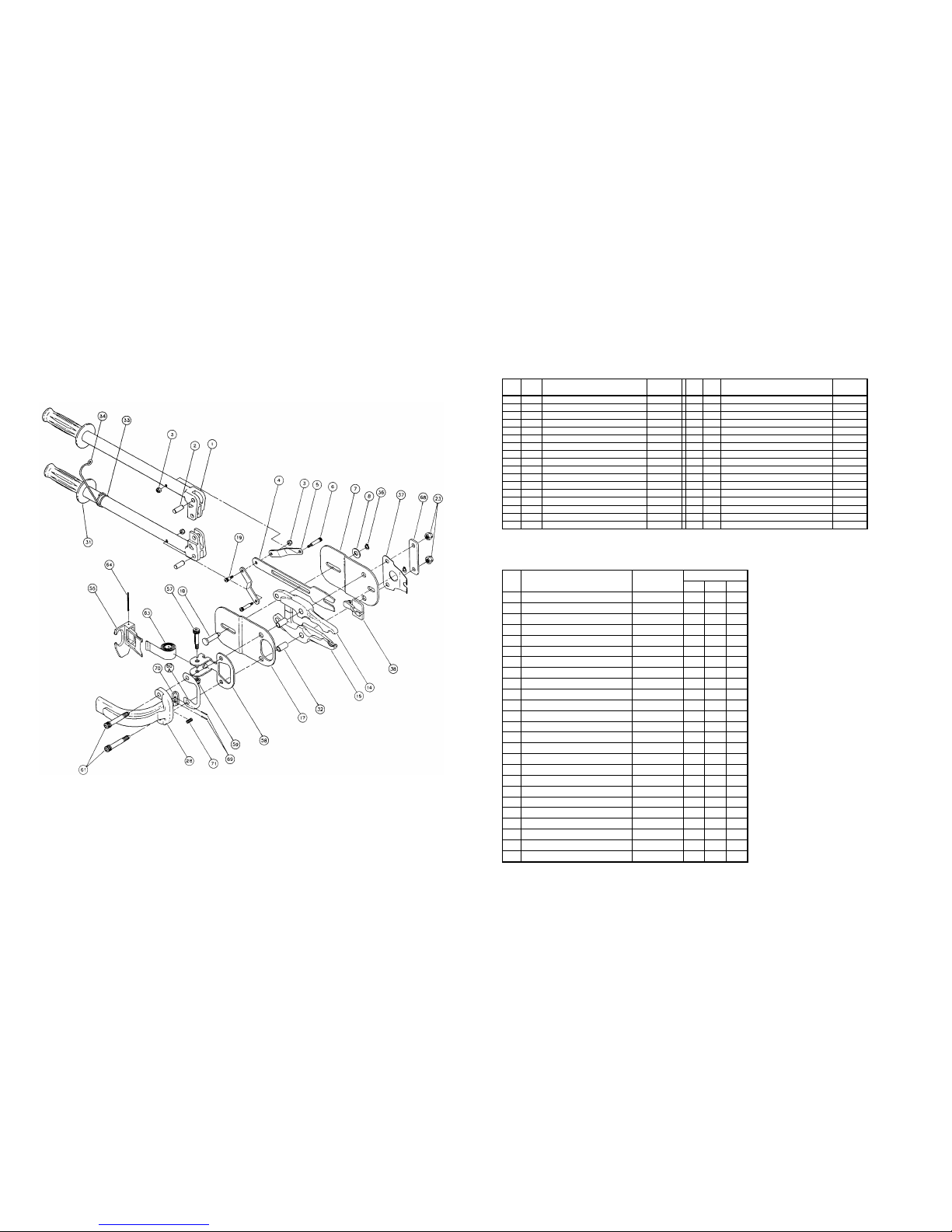
PARTS LIST
ITEM QTY. DESCRIPTION PART
NUMBER
ITEM QTY. DESCRIPTION PART
NUMBER
1 2 ASSEMBLY, HANDLE WELDMENT B03063F 33 1 O-RING, 15/16 X 1/8 SC74
2 2 PIN, DOWEL .375 X 1 SC70 34 1 LATCH, HANDLE SPRING A03104
3 3 NUT, NYLOCK 10-24 SC77 36 2 CLIP, LATCH PIN A02345
4 1 BLADE, FEEDER B03059F 37 1 SPRING, LATCH SC50 B02264F
5 2 LINK, CONNECTING A03057 38 1 LATCH, SC50 C02259F
6 2 BOLT, SHOULDER .25 X 1.00 SC71 55 1 PUSHER, SC50 B02286F
7 1 PLATE, BOTTOM SIDE C03061 57 1 BOLT, SPRING A02904
8 1 WASHER, 5/16 TL713000 58 1 BRACKET, MAG. SUPPORT SPRING B02900
14 1 JAW, LEFT D03064F 59 1 NUT, FLEXLOC TL727200
15 1 JAW, RIGHT D03065F 60A 1 SHIM, SC50 (.030) A02265
17 1 PLATE, TOP SIDE C03060 61 2 BOLT, JAW SC50 A02289
18 1 PIN, CLEVIS A03058F 63 1 SPRING, PUSHER SC50 B02297
19 1 BOLT, SHOULDER .25 X .375 SC73 64 1 PIN, ROLL SC50 A02368
23 2 NUT, FLEX SC50 A02356 68 1 PLATE, SUPPORT SC50 A02295
28 1 MAGAZINE, HAND PLIERS SC50 C022841F 69 2 PIN, ROLL SC50 A02362
31 2 GRIP, RUBBER SC69 70 1 SHOE, MAGAZINE SC50 C02261F
32 2 BUSHING, JAW B02932 71 1 SPRING, MAGAZINE SC50 A02350
RECOMMENDED SPARE PARTS LIST
ITEM DESCRIPTION PART NUMBER NUMBER OF TOOLS
1 5 10
1 ASSEMBLY, HANDLE WELDMENT B03063F 0 1 2
2 PIN, DOWEL .375 X 1 SC70 0 1 2
3 NUT, NYLOCK 10-24 SC77 0 3 6
4 BLADE, FEEDER B03059F 0 1 2
5 LINK, CONNECTING A03057 0 1 2
6 BOLT, SHOULDER .25 X 1.00 SC71 0 2 4
7 PLATE, BOTTOM SIDE C03061 0 1 2
8 WASHER, 5/16 TL713000 0 1 2
14 JAW, LEFT D03064F 0 1 1
15 JAW, RIGHT D03065F 0 1 1
17 PLATE, TOP SIDE C03060 0 1 1
18 PIN, CLEVIS A03058F 0 1 2
19 BOLT, SHOULDER .25 X .375 SC73 0 1 2
23 NUT, FLEX SC50 A02356 0 2 4
31 GRIP, RUBBER SC69 0 1 2
32 BUSHING, JAW B02932 0 1 2
33 O-RING, 15/16 X 1/8 SC74 0 1 2
36 CLIP, LATCH PIN A02345 0 1 2
37 SPRING, LATCH SC50 B02264F 1 2 4
38 LATCH, SC50 C02259F 0 2 3
59 NUT, FLEXLOC TL727200 0 1 2
60A SHIM, SC50 (.030) A02265 0 0 1
61 BOLT, JAW SC50 A02289 0 1 2
63 SPRING, PUSHER SC50 B02297 0 1 2
64 PIN, ROLL SC50 A02368 0 0 1
3 of 4 7/04
 Loading...