

Page 1

OPERATION and MAINTENANCE MANUAL
MANUAL DE OPERACIÓN Y DE MANTENIMIENTO
MANUEL D’INSTRUCTIONS ET D’ENTRETIEN
9R195756RA 01/12
BEFORE OPERATING THIS TOOL, ALL OPERATORS SHOULD STUDY THIS MANUAL TO
UNDERSTAND AND FOLLOW THE SAFETY WARNINGS AND INSTRUCTIONS. KEEP THESE
INSTRUCTIONS WITH THE TOOL FOR FUTURE REFERENCE. IF YOU HAVE ANY
QUESTIONS, CONTACT YOUR STANLEY TOOLS REPRESENTATIVE OR DISTRIBUTOR.
ANTES DE OPERAR ESTA HERRAMIENTA, TODOS LOS OPERADORES DEBERÁN
ESTUDIAR ESTE MANUAL PARA PODER COMPRENDER Y SEGUIR LAS ADVERTENCIAS
SOBRE SEGURIDAD Y LAS INSTRUCCIONES. MANTENGA ESTAS INSTRUCCIONES CON
LA HERRAMIENTA PARA FUTURA REFERENCIA, SI TIENE ALGUNA DUDA, COMUNÍQUESE
CON SU REPRESENTANTE DE STANLEY TOOLS O CON SU DISTRIBUIDOR.
LIRE ATTENTIVEMENT LE PRÉSENT MANUEL AVANT D’UTILISER L’APPAREIL. PRÉTER
UNE ATTENTION TOUTE PARTICULIÈRE AUX CONSIGNES DE SÉCURITÉ ET AUX
AVERTISSEMENTS. GARDER CE MANUEL AVEC L’OUTIL POUR FUTUR RÉFÉRENCE. SI
VOUS AVEZ DES QUESTIONS, CONTACTEZ VOTRE REPRÉSENTANT OU VOTRE
CONCESSIONNAIRE STANLEY TOOLS.
SB1850BN
BRAD NAILER
CLAVADORA DE PUNTILLAS
CLOUEUSE DE FINITION
Page 2

INTRODUCTION
T
he SB1850BN is a precision-built tool, designed for high speed, high volume nailing. This tool will deliver
efficient, dependable service when used correctly and with care. As with any fine power tool, for best
performance the manufacturer’s instructions must be followed. Please study this manual before operating the
tool and understand the safety warnings and cautions. The instructions on installation, operation and
m
aintenance should be read carefully, and the manual kept for reference. NOTE: Additional safety measures
may be required because of your particular application of the tool.
INDEX
S
afety Instructions . . . . . . . . . . . . . . . . . . . . . . . . . . . . . . . . . . . . . . . . . . . . . . . . . . . 3
T
ool Specifications . . . . . . . . . . . . . . . . . . . . . . . . . . . . . . . . . . . . . . . . . . . . . . . . . . . 4
L
ubrication . . . . . . . . . . . . . . . . . . . . . . . . . . . . . . . . . . . . . . . . . . . . . . . . . . . . . . . . 4
Air Supply and Connections . . . . . . . . . . . . . . . . . . . . . . . . . . . . . . . . . . . . . . . . . . . . 5
L
oading the Tool . . . . . . . . . . . . . . . . . . . . . . . . . . . . . . . . . . . . . . . . . . . . . . . . . . . . 6
Tool Operation . . . . . . . . . . . . . . . . . . . . . . . . . . . . . . . . . . . . . . . . . . . . . . . . . . . . . . 7
Maintaining the Pneumatic Tool . . . . . . . . . . . . . . . . . . . . . . . . . . . . . . . . . . . . . . . . . 8
Depth Adjustment . . . . . . . . . . . . . . . . . . . . . . . . . . . . . . . . . . . . . . . . . . . . . . . . . . . . 8
Trouble Shooting . . . . . . . . . . . . . . . . . . . . . . . . . . . . . . . . . . . . . . . . . . . . . . . . . . . . 9
Accessories . . . . . . . . . . . . . . . . . . . . . . . . . . . . . . . . . . . . . . . . . . . . . . . . . . . . . . . . 9
LIMITED WARRANTY
STANLEY TOOLS ("STANLEY") warrants to the original retail purchaser that this product is free from defects
in material and workmanship, and agrees to repair or replace, at STANLEY option, any defective product within
1 year from the date of purchase. This warranty is not transferable. It only covers damage resulting from defects
in material or workmanship, and it does not cover conditions or malfunctions resulting from normal wear,
neglect, abuse, accident or repairs attempted or made by other than our regional repair center or authorized
warranty service center. Driver blades, bumpers and o-rings are considered normally wearing parts.
THIS WARRANTY IS IN LIEU OF ALL OTHER EXPRESS WARRANTIES. ANY WARRANTY OF
MERCHANTABILITY OR FITNESS FOR A PARTICULAR PURPOSE IS LIMITED TO THE DURATION OF THIS
WARRANTY. STANLEY SHALL NOT BE LIABLE FOR ANY INCIDENTAL OR CONSEQUENTIAL DAMAGES.
This warranty is limited to sales in the United States and Canada. Some states do not allow limitations on how
long an implied warranty lasts, or the exclusion or limitation of incidental or consequential damages, so the
above limitations or exclusions may not apply to you. This warranty gives you specific legal rights, and you may
also have other rights which vary from state to state.
To obtain warranty service, return the product at your expense together with proof of purchase to a STANLEY
regional or authorized warranty repair center. You may also contact us at 1-800-556-6696 for the location of
authorized warranty service centers in your area.
-2-
Page 3
-3-
SAFETY INSTRUCTIONS
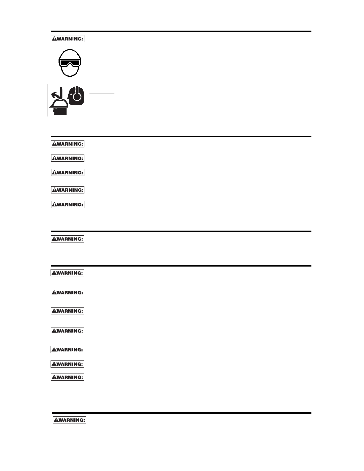
E
YE PROTECTIONwhich conforms to ANSI specifications and provides protection against
flying particles both from the FRONT and SIDE should ALWAYS be worn by the operator and
others in the work area when connecting to air supply, loading, operating or servicing this
tool. Eye protection is required to guard against flying fasteners and debris, which could
c
ause severe eye injury.
The employer and/or user must ensure that proper eye protection is worn. Eye protection
equipment must conform to the requirements of the American National Standards Institute,
A
NSI Z87.1 and provide both frontal and side protection. NOTE: Non-side shielded
spectacles and face shields alone do not provide adequate protection.
C
AUTION:
A
dditional Safety Protection will be required in some environments. For example,
t
he working area may include exposure to noise level which can lead to hearing damage.
The employer and user must ensure that any necessary hearing protection is provided and
u
sed by the operator and others in the work area. Some environments will require the use
of head protection equipment. When required, the employer and user must ensure that head
p
rotection conforming to ANSI Z89.1 is used.
AIR SUPPLY AND CONNECTIONS
Do not use oxygen, combustible gases, or bottled gases as a power source for this tool as
tool may explode, possibly causing injury.
Do not use supply sources which can potentially exceed 200 P.S.I.G. as tool may burst,
possibly causing injury.
The connector on the tool must not hold pressure when air supply is disconnected. If a
wrong fitting is used, the tool can remain charged with air after disconnecting and thus will
be able to drive a fastener even after the air line is disconnected possibly causing injury.
Do not pull trigger or depress contact arm while connected to the air supply as the tool may
cycle, possibly causing injury.
Always disconnect air supply: 1.) Before making adjustments; 2.) When servicing the tool;
3.) When clearing a jam; 4.) When tool is not in use; 5.) When moving to a different work area,
as accidental actuation may occur, possibly causing injury.
LOADING TOOL
When loading tool: 1.) Never place a hand or any part of body in fastener discharge area of
tool; 2.) Never point tool at anyone; 3.) Do not pull the trigger or depress the trip as
accidental actuation may occur, possibly causing injury.
OPERATION
Always handle the tool with care: 1.) Never engage in horseplay; 2.) Never pull the trigger
unless nose is directed toward the work; 3.) Keep others a safe distance from the tool while
tool is in operation as accidental actuation may occur, possibly causing injury.
The operator must not hold the trigger pulled on contact arm tools except during fastening
operation as serious injury could result if the trip accidentally contacted someone or
something, causing the tool to cycle.
Keep hands and body away from the discharge area of the tool. A contact arm tool may
bounce from the recoil of driving a fastener and an unwanted second fastener may be
driven possibly causing injury.
Check operation of the contact arm mechanism frequently. Do not use the tool if the arm is
not working correctly as accidental driving of a fastener may result. Do not interfere with
the proper operation of the contact arm mechanism.
Do not drive fasteners on top of other fasteners or with the tool at an overly steep angle as
this may cause deflection of fasteners which could cause injury.
Do not drive fasteners close to the edge of the work piece as the wood may split, allowing
the fastener to be deflected possibly causing injury.
This nailer produces SPARKS during operation. NEVER use the nailer near flammable
substances, gases or vapors including lacquer, paint, benzine, thinner, gasoline, adhesives,
mastics, glues or any other material that is -- or the vapors, fumes or byproducts of which are -flammable, combustible or explosive. Using the nailer in any such environment could cause an
EXPLOSION resulting in personal injury or death to user and bystanders.
MAINTAINING THE TOOL
When working on air tools note the warnings in this manual and use extra care when
evaluating problem tools.
Page 4
-4-
TOOL SPECIFICATIONS
A
ll screws and nuts are metric.
FASTENER SPECIFICATIONS:
TOOL MODEL BRAD SERIES GAUGE FASTENER RANGE
SB1850BN BT1300 18 5/8” - 2”
TOOL AIR FITTING:
These tools use a free-flow connector plug, 1/4 N.P.T. The inside diameter should be .200” (5mm) or larger.
The fitting must be capable of discharging tool air pressure when disconnected from the air supply.
OPERATING PRESSURE:
70 to 100 p.s.i.g. (4.9 to 7.0 kg/cm2). Select the operating pressure within this range for best fastener
performance.
DO NOT EXCEED THIS RECOMMENDED OPERATING PRESSURE.
OPERATION
SEQUENTIAL TRIP
The Sequential Trip requires the operator to hold the tool against the work before pulling the trigger. This makes
accurate fastener placement easier, for instance on framing, toe nailing and crating applications.The
Sequential Trip allows exact fastener location without the possibility of driving a second fastener on recoil. The
Sequential Trip Tool has a positive safety advantage because it will not accidentally drive a fastener if the tool
is contacted against the work – or anything else – while the operator is holding the trigger pulled.
MODEL IDENTIFICATION:
Refer to Operation Instructions on page 7
before proceeding to use this tool.
SEQUENTIAL TRIP
Identified by:
GRAY TRIGGER
LUBRICATIION
Frequent, but not excessive, lubrication is required for best performance. Oil added through the air line connection will
lubricate the internal parts. Use Air Tool Lubricant, Mobil Velocite #10, or equivalent. Do not use detergent oil or additives
as these lubricants will cause accelerated wear to the seals and bumpers in the tool, resulting in poor tool performance
and frequent tool maintenance.
If no airline lubricator is used, add oil during use into the air fitting on the tool once or twice a day. Only a few
drops of oil at a time is necessary. Too much oil will only collect inside the tool and will be noticeable in the exhaust
cycle.
COLD WEATHER OPERATION:
For cold weather operation, near and below freezing, the moisture in the air line may freeze and prevent tool
operation. We recommend the use of WINTER FORMULA air tool lubricant or permanent antifreeze (ethylene glycol)
as a cold weather lubricant.
CAUTION:
Do not store tools in a cold weather environment to prevent frost or ice formation on the tools
operating valves and mechanisms that could cause tool failure.
NOTE:
Some commercial air line drying liquids are harmful to “O”-rings and seals – do not use these low
temperature air dryers without checking compatibility.
M
O
D
E
L
T
O
O
L A
C
TUA
TI
O
N
LE
N
G
TH
H
E
I
G
H
T
W
I
D
TH
W
E
I
G
H
T
S
B
1
8
5
0
B
N
S
e
q
u
e
n
t
i
a
l
T
r
i
p
9
.
2
5
”
9
.
5
”
2
”
2
.
6
9
l
b
s
.
Page 5

AIR SUPPLY AND CONNECTIONS
Do not use oxygen, combustible gases, or bottled gases as a power source for this
tool as tool may explode, possibly causing injury.
FITTINGS:
Install a male plug on the tool which is free flowing and which will release air pressure from the tool when
disconnected from the supply source.
HOSES:
A
ir hoses should have a minimum of 150 p.s.i. (10.6 kg/cm
2
)
working pressure rating or 150 percent of the
maximum pressure that could be produced in the air system. The supply hose should contain a fitting that
w
ill provide “quick disconnecting” from the male plug on the tool.
SUPPLY SOURCE:
U
se only clean regulated compressed air as a power source for this tool. NEVER USE OXYGEN,
COMBUSTIBLE GASES, OR BOTTLED GASES, AS A POWER SOURCE FOR THIS TOOL AS TOOL
MAY EXPLODE.
REGULATOR:
A pressure regulator with an operating pressure of 0 - 125 p.s.i. (0 - 8.79 kg/cm2) is required to control the
operat iing pressure for safe operation of this tool. Do not connect this tool to air pressure which can
potentially exceed 200 p.s.i. (14 KG/CM2)as tool may fracture or burst, possibly causing injury.
OPERATING PRESSURE:
Do not exceed recommended maximum operating pressure as tool wear will be greatly increased. The air
supply must be capable of maintaining the operating pressure at the tool. Pressure drops in the air supply
can reduce the tool’s driving power. Refer to “TOOL SPECIFICATIONS” for setting the correct operating
pressure for the tool.
FILTER:
Dirt and water in the air supply are major causes of wear in pneumatic tools. A filter will help to get the best
performance and minimum wear from the tool. The filter must have adequate flow capacity for the specific
installation. The filter has to be kept clean to be effective in providing clean compressed air to the tool.
Consult the manufacturer’s instructions on proper maintenance of your filter. A dirty and clogged filter will
cause a pressure drop which will reduce the tool’s performance.
-5-
Page 6
IN ADDITION TO THE OTHER WARNINGS CONTAINED IN THIS
MANUAL OBSERVE THE FOLLOWING FOR SAFE OPERATION
• Use the STANLEY pneumatic tool only for the purpose for which it was designed.
• Never use this tool in a manner that could cause a fastener to be directed toward the user or others
in the work area.
• Do not use the tool as a hammer.
• Always carry the tool by the handle. Never carry the tool by the air hose.
• Do not alter or modify this tool from the original design or function.
• Always be aware that misuse and improper handling of this tool can cause injury to yourself and others.
• Never clamp or tape the trigger or contact trip in an actuated position.
• Never leave a tool unattended with the air hose attached.
• Do not operate this tool if it does not contain a legible WARNING LABEL.
• Do not continue to use a tool that leaks air or does not function properly. Notify your nearest
STANLEY representative if your tool continues to experience functional problems.
-6-
EYE PROTECTION which conforms to ANSI specifications and provides protection
a
gainst flying particles both from the FRONT and SIDE should ALWAYS be worn by the
o
perator and others in the work area when loading, operating or servicing this tool. Eye
protection is required to guard against flying fasteners and debris, which could cause
severe eye injury.
The employer and/or user must ensure that proper eye protection is worn. Eye
p
rotection equipment must conform to the requirements of the American National
S
tandards Institute, ANSI Z87.1 and provide both frontal and side protection. NOTE:
Non-side shielded spectacles and face shields alone do not provide adequate protection.
TO PREVENT ACCIDENTAL INJURIES:
• Never place a hand or any other part of the body in nail discharge area of tool
while the air supply is connected.
•
Never point the tool at anyone else.
• Never engage in horseplay.
• Never pull the trigger unless nose is directed at the work.
• Always handle the tool with care.
• Do not pull the trigger or depress the trip mechanism while loading the tool.
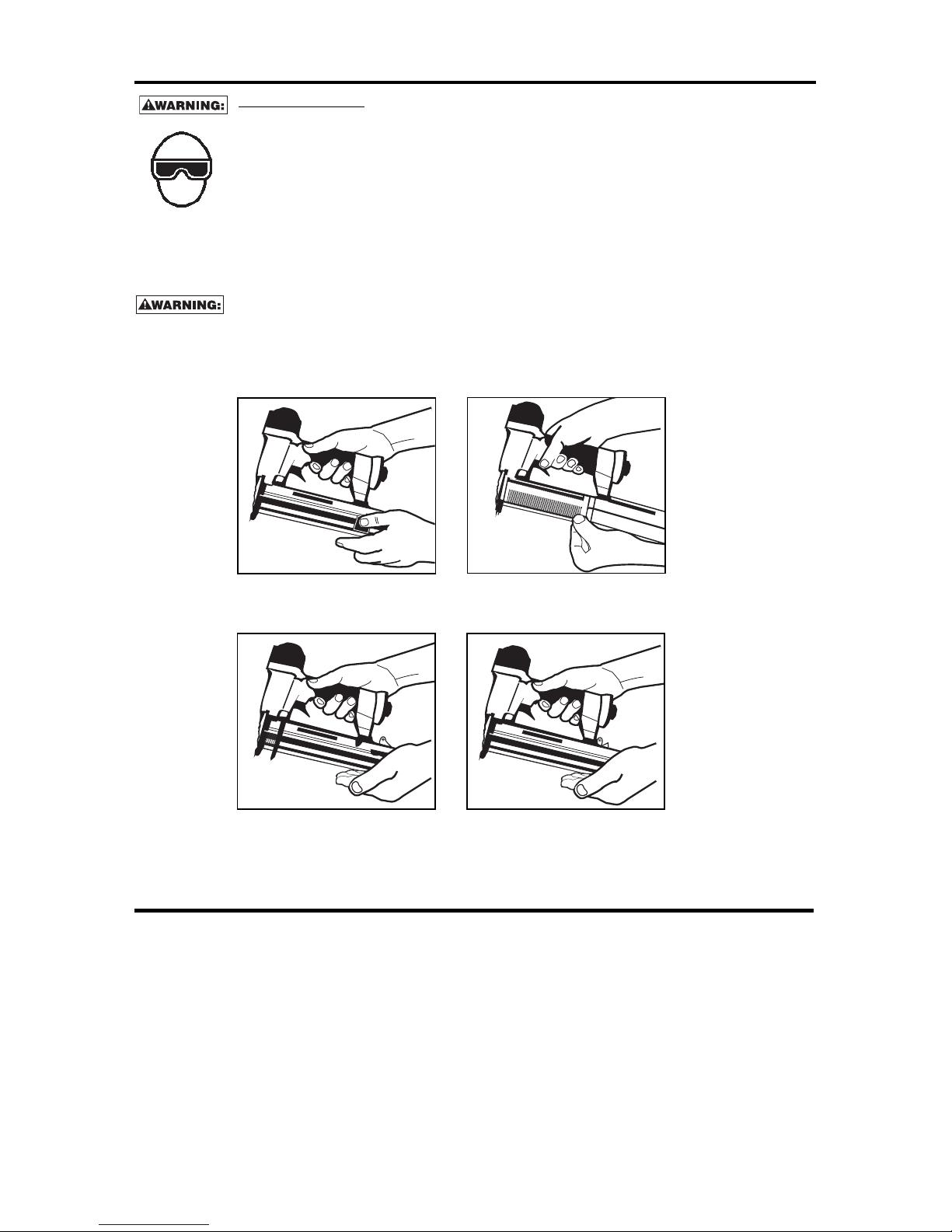
LOADING THE SB1850BN
1. Disengage the latch and
pull back magazine side.
2. With magazine fully openinsert fasteners.
Points must be against bottom of magazine.
3. Push magazine forward.
4. Continue pushing until latch is engaged.
Page 7

BEFORE HANDLING OR OPERATING THIS TOOL:
I. READ AND UNDERSTAND THE WARNINGS CONTAINED IN THIS MANUAL.
II. REFER TO “TOOL SPECIFICATIONS” IN THIS MANUAL TO IDENTIFY THE
OPERATING SYSTEM ON YOUR TOOL.
OPERATION
The operator must not hold the trigger pulled on contact trip tools except during
fastening operation, as serious injury could result if the trip accidentally contacted
someone or something, causing the tool to cycle.
Keep hands and body away from the discharge area of the tool. A contact trip tool
may bounce from the recoil of driving a fastener and an unwanted second fastener
may be driven, possibly causing injury.
SEQUENTIAL TRIP OPERATION
The SEQUENTIAL TRIP MODEL contains a contact trip that operates in conjunction with the trigger to drive
a fastener. To operate a sequential trip tool, first position the contact trip on the work surface WITHOUT
PULLING THE TRIGGER. Depress the contact trip and then pull the trigger to drive a fastener. As long as
the contact trip is contacting the work and is held depressed, the tool will drive a fastener each time the
trigger is depressed. If the contact trip is allowed to leave the work surface, the sequence described above
must be repeated to drive another fastener.
TOOL OPERATION CHECK:
CAUTION: Remove all fasteners from tool before performing tool operation check.
SEQUENTIAL TRIP OPERATION:
A. Press the contact trip against the work surface, without touching the trigger.
THE TOOL MUST NOT CYCLE.
B. Hold the tool off the work surface and pull the trigger.
THE TOOL MUST NOT CYCLE.
Release the trigger. The trigger must return to the trigger stop on the frame.
C. Pull the trigger and press the contact trip against the work surface.
THE TOOL MUST NOT CYCLE.
D. With finger off the trigger, press the contact trip against the work surface. Pull the trigger.
THE TOOL MUST CYCLE.
TOOL OPERATION
EYE PROTECTION which conforms to ANSI specifications and provides protection
a
gainst flying particles both from the FRONT and SIDE should ALWAYS be worn by the
o
perator and others in the work area when loading, operating or servicing this tool.
Eye protection is required to guard against flying fasteners and debris, which could
cause severe eye injury.
The employer and/or user must ensure that proper eye protection is worn. Eye
protection equipment must conform to the requirements of the American National
Standards Institute, ANSI Z87.1 and provide both frontal and side protection. NOTE:
N
on-side shielded spectacles and face shields alone do not provide adequate protection.
-7-
Page 8
MAINTAINING THE PNEUMATIC TOOL
When working on air tools, note the warnings in this manual and use extra care
e
valuating problem tools.
C
AUTION: Pusher spring (constant force spring). Caution must be used when working with the spring
assembly. The spring is wrapped around, but not attached to, a roller. If the spring is extended beyond
i
ts length, the end will come off the roller and the spring will roll up with a snap, with a chance of
pinching your hand. Also the edges of the spring are very thin and could cut. Care must also be taken
t
o insure no permanent kinks are put in the spring as this will reduce the springs force.
REPLACEMENT PARTS:
S
TANLEY replacement parts are recommended. Do not use modified parts or parts which will not give
equivalent performance to the original equipment.
ASSEMBLY PROCEDURE FOR SEALS:
When repairing a tool, make sure the internal parts are clean and lubricated. Use Parker “O”-LUBE or
equivalent on all “O”-rings. Coat each “O”-ring with “O”-LUBE before assembling. Use a small amount of oil
on all moving surfaces and pivots. After reassembly add a few drops of Air Tool Lubricant through the air line
fitting before testing.
AIR SUPPLY-PRESSURE AND VOLUME:
Air volume is as important as air pressure. The air volume supplied to the tool may be inadequate because
of undersize fittings and hoses, or from the effects of dirt and water in the system. Restricted air flow will
prevent the tool from receiving an adequate volume of air, even though the pressure reading is high. The
results will be slow operation, misfeeds or reduced driving power. Before evaluating tool problems for these
symptoms, trace the air supply from the tool to the supply source for restrictive connectors, swivel fittings,
low points containing water and anything else that would prevent full volume flow of air to the tool.
-8-
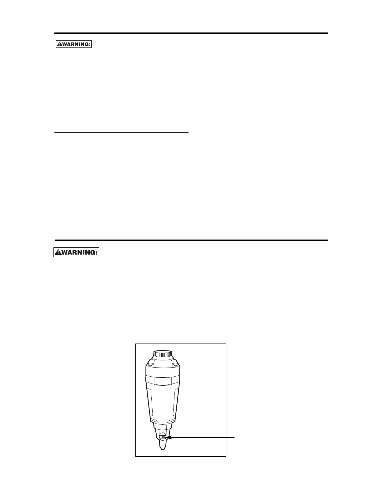
The Fastener Control adjustment feature provides close control of the fastener drive depth; from flush
with the work surface to shallow or deep countersink. First, set the air pressure for consistent drive in the
specific work. Then use the Fastener Control adjustment to give the desired depth of drive.
TO ADJUST FASTENER CONTROL ADJUSTMENT:
1. With air pressure set, drive a few fasteners into a representative material sample to
determine if adjustment is necessary.
2. If adjustment is required, disconnnect air supply.
SB1850BN FASTENER CONTROL ADJUSTMENT
Always disconnect air supply: 1. Before making adjustments; 2. When servicing
the tool; 3. When clearing a jam; 4. When tool is not in use; 5. When moving to a
different work area, as accidental actuation may occur, possibly causing injury.
Depth Adjustment Knob
SB1850BN
DEPTH ADJUSTMENT
Page 9

-9-
Trigger valve housing leaks air O-ring cut or cracked . . . . . . . . . . . . . . .Replace O-ring
Trigger valve stem leaks air O-ring/seals cut or cracked . . . . . . . . . .Replace trigger valve assembly
Frame/nose leaks air Loose nose screws . . . . . . . . . . . . . . . .Tighten and recheck
O-ring or Gasket is cut or cracked . . . . .Replace O-ring or gasket
Bumper cracked/worn . . . . . . . . . . . . . .Replace bumper
Frame/cap leaks air Damaged gasket or seal . . . . . . . . . . . .Replace gasket or seal
Cracked/worn head valve bumper . . . . .Replace bumper
Loose cap screws . . . . . . . . . . . . . . . . .Tighten and recheck
Failure to cycle Air supply restriction . . . . . . . . . . . . . . .Check air supply equipment
Tool dry, lack of lubrication . . . . . . . . . .Use Air Tool Lubricant
Worn head valve O-rings . . . . . . . . . . . .Replace O-rings
Broken cylinder cap spring . . . . . . . . . .Replace cylinder cap spring
Head valve stuck in cap . . . . . . . . . . . . .Disassemble/Check/Lubricate
Lack of power; slow to cycle Tool dry, lacks lubrication . . . . . . . . . . . .Use Air Tool Lubricant
Broken cylinder cap spring . . . . . . . . . .Replace cap spring
O-rings/seals cut or cracked . . . . . . . . .Replace O-rings/seals
Exhaust blocked . . . . . . . . . . . . . . . . . .Check bumper, head valve spring, muffler
Trigger assembly worn/leaks . . . . . . . . .Replace trigger assembly
Dirt/tar build up on driver . . . . . . . . . . . .Disassemble nose/driver to clean
Cylinder sleeve not seated correctly
on bottom bumper . . . . . . . . . . . . . . . . .Disassemble to correct
Head valve dry . . . . . . . . . . . . . . . . . . . .Disassemble/lubricate
Air pressure too low . . . . . . . . . . . . . . . .Check air supply equipment
Skipping fasteners; intermittent feed Worn bumper . . . . . . . . . . . . . . . . . . . . .Replace bumper
Tar/dirt in driver channel . . . . . . . . . . . .Disassemble and clean nose and driver
Air restriction/inadequate air flow through
quick disconnect socket and plug . . . . .Replace quick disconnect fittings
Worn piston O-ring . . . . . . . . . . . . . . . .Replace O-ring, check driver
Tool dry, lacks lubrication . . . . . . . . . . . .Use Air Tool Lubricant
Damaged pusher spring . . . . . . . . . . . .Replace spring
Low air pressure . . . . . . . . . . . . . . . . . .Check air supply system to tool
Loose magazine nose screws . . . . . . . .Tighten all screws
Fasteners too short for tool . . . . . . . . . .Use only recommended fasteners
Bent fasteners . . . . . . . . . . . . . . . . . . . .Discontinue using these fasteners
Wrong size fasteners . . . . . . . . . . . . . . .Use only recommended fasteners
Leaking head cap gasket . . . . . . . . . . . .Tighten screws/replace gasket
Trigger valve O-ring cut/worn . . . . . . . . .Replace O-ring
Broken/chipped driver . . . . . . . . . . . . . .Replace driver (check piston O-ring)
Dry/dirty magazine . . . . . . . . . . . . . . . .Clean/lubricate use Air Tool Lubricant
Worn magazine . . . . . . . . . . . . . . . . . . .Replace magazine
Fasteners jam in tool Driver channel worn . . . . . . . . . . . . . . . .Replace nose/check door
Wrong size fasteners . . . . . . . . . . . . . . .Use only recommended fasteners
Bent fasteners . . . . . . . . . . . . . . . . . . . .Discontinue using these fasteners
Loose magazine/nose screws . . . . . . . .Tighten all screws
Broken/chipped driver . . . . . . . . . . . . . .Replace driver
PROBLEM CAUSE CORRECTION
ACCESSORIES AVAILABLE
PREMOIL-4OZ 4 oz. Premium Air Tool Lubricant
WINTEROIL-4OZ 4 oz. Winter Air Tool Lubricant
TROUBLE SHOOTING
Page 10

INTRODUCCIÓN
Las SB1850BN es una herramienta clavadora construida a precisión, diseñada para funcionar a alta velocidad
y
con alto volumen. Al igual que con cualquier herramienta automática de calidad, el mejor rendimiento se
obtiene siguiendo las instrucciones del fabricante. Se le recomienda estudiar este manual antes de operar la
h
erramienta y comprender las advertencias y precauciones de seguridad. Las instrucciones relativas a la
instalación, operación y mantenimiento se deben leer detenidamente y el manual debe guardarse como
referencia. NOTA: Es posible que se requieran medidas adicionales de seguridad en consideración de la
a
plicación particular que usted destina a la herramienta.
ÍNDICE
Instrucciones de seguridad . . . . . . . . . . . . . . . . . . . . . . . . . . . . . . . . . . . . . . . . . . . . 11
Especificaciones de la herramienta . . . . . . . . . . . . . . . . . . . . . . . . . . . . . . . . . . . . . . 12
L
ubricación . . . . . . . . . . . . . . . . . . . . . . . . . . . . . . . . . . . . . . . . . . . . . . . . . . . . . . . . 12
Suministro de aire y conexiones . . . . . . . . . . . . . . . . . . . . . . . . . . . . . . . . . . . . . . . . 13
Cómo cargar la herramienta . . . . . . . . . . . . . . . . . . . . . . . . . . . . . . . . . . . . . . . . . . . 14
Operación de la herramienta . . . . . . . . . . . . . . . . . . . . . . . . . . . . . . . . . . . . . . . . . . . 15
Mantenimiento de la herramienta neumática . . . . . . . . . . . . . . . . . . . . . . . . . . . . . . 16
Ajuste de la profundidad. . . . . . . . . . . . . . . . . . . . . . . . . . . . . . . . . . . . . . . . . . . . . . . 16
Diagnóstico de fallas . . . . . . . . . . . . . . . . . . . . . . . . . . . . . . . . . . . . . . . . . . . . . . . . . 17
Accesorios . . . . . . . . . . . . . . . . . . . . . . . . . . . . . . . . . . . . . . . . . . . . . . . . . . . . . . . . 17
GARANTÍA LIMITADA
STANLEY TOOLS ("STANLEY") garantiza al comprador original al por menor que este producto está exento
de defectos de material y fabricación, además se compromete a reparar o cambiar, a opción de STANLEY,
cualquier producto defectuoso dentro de 1 año de la fecha de compra. Esta garantía no es transferible.
Solamente cubre daños resultantes de defectos en material o fabricación, y no cubre condiciones o
desperfectos resultantes del desgaste normal, negligencia, abuso, accidente o reparaciones intentadas o
efectuadas por terceros ajenos a nuestro centro regional de reparaciones o al centro de servicio bajo garantía.
Las aspas del impulsor, los topes y las juntas tóricas se consideran componentes de desgaste normal.
ESTA GARANTÍA REEMPLAZA TODAS LAS DEMÁS GARANTÍAS EXPRESAS. TODA GARANTÍA DE
COMERCIABILIDAD O IDONEIDAD PARA UN FIN PARTICULAR SE LIMITA A LA DURACIÓN DE ESTA
GARANTÍA. STANLEY NO SERÁ RESPONSABLE DE DAÑOS FORTUITOS NI CONSECUENCIALES.
Esta garantía se limita a ventas dentro de los Estados Unidos y Canadá. Algunos estados no permiten
limitaciones a la duración de una garantía implícita ni la exclusión o limitación de daños fortuitos o
consecuenciales, de modo que las limitaciones o exclusiones anteriores pueden no corresponder a su caso.
Esta garantía le concede derechos legales específicos, y usted puede tener también otros derechos que varían
de un estado a otro.
Para obtener servicio bajo la garantía, devuelva el producto con cargo a nosotros junto con su comprobante
de compra dirigido al centro regional o al centro de reparaciones bajo garantía de STANLEY. Puede llamarnos
también al 1-800-556-6696 para obtener la dirección de los centros autorizados de servicio bajo garantía en
su área.
-10-
Page 11

-11-
INSTRUCCIONES DE SEGURIDAD
C
uando el equipo está conectado al suministro de aire, tanto el operador como todas las personas que se
encuentren en el área de trabajo, SIEMPRE deben usar PROTECCIÓN OCULAR que cumpla las
especificaciones ANSI para resguardo contra partículas volantes arrojadas desde el FRENTE o los
LATERALES. Dicha protección ocular se requiere para proteger contra residuos y remaches volantes, que
p
odrían causar graves lesiones en los ojos.
E
l empleador y/o usuario debe asegurar que la debida protección para los ojos sea usada. El equipo
protector de los ojos debe cumplir con los requisitos del Instituto de Normas Nacionales Americano
(American National Standards Institute), ANSI Z87.1 y debe proveer protección de frente y de los lados.
N
OTA: Las gafas de seguridad que no están protegidas de los lados y las máscaras por sí solas no proveen
la debida protección.
PRECAUCIÓN:
En algunos entornos será necesaria protección de seguridad adicional. Por ejemplo, es
p
osible que el área de trabajo incluya la exposición a niveles de ruido que pueden dañar el oído. El empleador
y el usuario deben asegurarse de que cualquier protección necesaria para los oídos sea provista y utilizada
p
or el operador y demás personas en el área de trabajo. Algunos entornos requieren el uso de aparatos de
protección para la cabeza. Cuando sea necesario, el empleador y el usuario deben asegurarse de que se
utilice protección para la cabeza en conformidad con la norma ANSI Z89.1.
SUMINISTRO DE AIRE Y CONEXIONES
No utilice oxígeno ni gases combustibles o embotellados como fuente de suministro para esta
herramienta, ya que la herramienta puede estallar, posiblemente causando lesiones.
N
o utilice fuentes de suministro que potencialmente excedan las 14 Kg/cm
2
(
13,8 bars) ya que la
h
erramienta puede estallar, posiblemente causando lesiones.
El conector de la herramienta no debe tener presión al desconectarse el suministro de aire. Si se
utiliza una conexión equivocada, la herramienta puede permanecer cargada con aire después de
ser desconectada y por lo tanto podrá impulsar un sujetador aún después de que la línea de aire
sea desconectada, posiblemente causando lesiones.
No jale el gatillo o presione el brazo de contacto mientras esté conectado a un suministro de aire,
ya que la herramienta puede ciclar y causar lesiones.
Siempre desconecte el suministro de aire: 1.) Antes de efectuar ajustes; 2.) Al hacerle servicio a
la herramienta; 3.) Al despejar un atascamiento; 4.) Cuando la herramienta no esté en uso; 5.) Al
mudarse de un área distinta de trabajo, ya que se puede activar accidentalmente, posiblemente
causando lesiones.
AL CARGAR LA HERRAMIENTA
Al cargar la herramienta: 1.) Nunca coloque una mano o cualquier otra parte del cuerpo en el área
de descarga del sujetador de la herramienta; 2.) Nunca apunte la herramienta hacia otra persona;
3.) No hale el gatillo ni oprima el disparador ya que se puede activar accidentalmente,
posiblemente causando lesiones.
OPERACIÓN
Siempre maneje la herramienta con cuidado. 1.) Nunca participe en juegos rudos con la herramienta;
2.) Nunca hale el gatillo al menos que la nariz esté apuntada hacia el trabajo; 3.) Mantenga a las demás
personas a una distancia segura de la herramienta mientras la herramienta esté en operación ya que se
puede activar accidentalmente, causando posibles lesiones.
El operador no debe mantener el gatillo presionado en herramientas de brazo de contacto, excepto
durante la operación de sujeción ya que se podría generar una lesión grave si el interruptor contactara
accidentalmente alguna persona o cosa, causando que la herramienta cicle.
Mantenga las manos y el cuerpo alejados del área de descarga de la herramienta. Una herramienta con
brazo de contacto puede rebotar debido a la reculada al impulsar un sujetador y se puede impulsar
accidentalmente un segundo sujetador, causando posibles lesiones.
Verifique la operación del mecanismo del brazo de contacto frecuentemente. No utilice la herramienta
si el brazo no está funcionando correctamente ya que se puede impulsar accidentalmente otro
sujetador. No interfiera con la debida operación del mecanismo del brazo de contacto.
No meta los sujetadores encima de otros sujetadores o teniendo la herramienta demasiado
inclinada ya que esto podría causar que los sujetadores se desviaran, y a su vez causaran
lesiones.
No meta los sujetadores cerca del borde de la pieza de trabajo porque la madera podría separarse, lo
que permitiría que el sujetador se desviara y causara lesiones.
Esta clavadora produce CHISPAS durante la operación. NUNCA use la clavadora cerca de sustancias,
gases ni vapores inflamables, incluidos diluyentes, lacas, pintura, bencina, gasolina, adhesivos,
mástique, pegamentos ni ningún otro material que sea inflamable, combustible o explosivo -- o vapores,
emanaciones o subproductos que puedan serlo. Si se usa la clavadora en cualquier ambiente de este
tipo podría causar una EXPLOSION produciendo lesiones físicas o fatales para el usuario y las
personas en la cercanía.
MANTENIMIENTO DE LA HERRAMIENTA
Tome nota de las advertencias en este manual al trabajar con herramientas neumáticas y tenga
mayor cuidado al evaluar herramientas problemáticas.
Page 12

ESPECIFICACIONES DE LA HERRAMIENTA
Todos las medidas de tornillos y tuercas son métricas.
ESPECIFICACIONES DEL SUJETADOR:
MODELO DE LA HERRAMIENTA SERIE DEL CLAVO CALIBRE RANGO DEL SUJETADOR
S
B1850BN BT1300 18 5/8” - 2”
CONEXIÓN DE AIRE DE LA HERRAMIENTA:
Estas herramientas usan un enchufe conector de flujo libre de 1/4 N.P.T. El diámetro interior debe ser de 5 mm (0.2”) o mayor.
La conexión debe ser capaz de descargar la presión de aire de la herramienta cuando se desconecta del suministro de aire.
PRESIÓN DE OPERACIÓN:
4.9 a 7 kg/cm2(4.8 bars a 6.9 bars). Seleccione la presión de operación dentro de este rango para el mejor rendimiento de los
s
ujetadores. NO EXCEDA ESTA PRESIÓN DE OPERACIÓN RECOMENDADA.
OPERACIÓN
DISPARO SECUENCIAL
El Disparo Secuencial requiere que el operador mantenga la herramienta sobre la superficie del objeto antes de halar el gatillo.
Esto permite la precisa y fácil colocación de sujetadores en muchos trabajos, por ejemplo, en aplicaciones de construcción de
marcos, con clavos oblicuos y la construcción de cajones de construcción. El Disparo Secuencial permite la colocación exacta
de sujetadores sin la posibilidad de impulsar un segundo sujetador en la reculada. La Herramienta de Disparo Secuencial tiene
una ventaja de seguridad positiva, ya que no impulsará un sujetador accidentalmente si la herramienta entra en contacto con el
objeto de trabajo – o cualquier otra cosa – mientras el operador mantenga el gatillo halado.
IDENTIFICACIÓN DE MODELO
Consulte las Instrucciones de Operación en la
página 15 antes de usar esta herramienta.
DISPARO SECUENCIAL
Identificada por:
GATILLO GRIS
LUBRICACIÓN
Para el mejor rendimiento se requiere una lubricación frecuente pero no excesiva. El aceite añadido a través de la conexión de
la línea de aire lubricará las piezas internas. Use el Lubricante de Herramientas de Aire Mobil Velocite #10 de o un equi valente.
No use aceite detergente o aditivos, ya que estos lubricantes causan el desgaste acelerado de los sellos y los amortiguadores
de choque en la herramienta, dando como resultado un mal rendimiento de la herramienta y el mantenimiento frecuente de la
misma.
Si no se usa un lubricante de línea de aire, añada aceite cuando se esté usando en la conexión de aire en la herramienta una o
dos veces al día. Basta con añadir unas cuantas gotas cada vez. Si añade demasiado aceite, se acumulará dentro de la
herramienta y se notará en el ciclo de escape.
OPERACIÓN EN LA ÉPOCA DE FRÍO:
Para la operación en la época de frío, cerca o bajo de la temperatura de congelación, la humedad en la línea de aire puede
congelarse e impedir que la herramienta funcione. Recomendamos el uso del lubricante de herramientas de aire WINTER
FORMULA o un anti-descongelante permanente (glicol de etileno) como un lubricante para la época de frío.
NOTA: No almacene las herramientas en ambientes fríos para impedir que se forme el hielo en las
válvulas y los mecanismos de operación de la herramienta, lo cual podría hacer que la herramienta
falle.
NOTA: Algunos líquidos comerciales secadores de líneas de aire pueden dañar los anillos en “O”
y los sellos — no use estos secadores de aire de baja temperatura sin verificar su compatibilidad.
ACTIVACIÓN
MODELO DE LA HERRAMIENTA LARGO ALTURA ANCHO PESO
SB1850BN Disparo secuencial 9.25” 9.5” 2” 2.69 lbs.
-12-
Page 13

-13-
SUMINISTRO DE AIRE Y CONEXIONES
No use oxígeno, gases combustibles o gases embotellados como una fuente de
suministro para esta herramienta, ya que la herramienta puede estallar, posiblemente
causando lesiones.
CONEXIONES:
Instale un enchufe macho en la herramienta que fluya libre y que descargue la presión de aire de la herramienta cuando sea
d
esconectada de la fuente de suministro.
MANGUERAS:
Las mangueras de aire deben tener un mínimo de clasificación de presión de operación de 10,5 kg/cm2(10,3 bars) ó 150
porciento de la presión máxima de operación que podría producirse en el sistema de aire. La manguera de suministro debe
c
ontener una conexión que provea un “desconectado rápido” del enchufe macho en la herramienta.
FUENTE DE SUMINISTRO:
Use sólo aire comprimido regulado limpio como una fuente de suministro para esta herramienta. NUNCA USE OXÍGENO,
G
ASES COMBUSTIBLES O GASES EMBOTELLADOS COMO UNA FUENTE DE SUMINISTRO PARA ESTA HERRAMIENTA,
YA QUE LA HERRAMIENTA PODRÍA ESTALLAR.
REGULADOR:
Se requiere un regulador de presión con una presión de operación de 0-8,7 kg/cm2(8,6 bars) para controlar la presión de
o
peración para la segura operación de esta herramienta. No conecte esta herramienta a una presión de aire que potencialmente
exceda 14 kg/cm
2
(13,8 bars), ya que la herramienta puede fracturarse o estallar, posiblemente causando lesiones.
PRESIÓN DE OPERACIÓN:
No exceda una presión de operación de 7,0 kg/cm2(6,9 bars) El suministro de aire debe ser capaz de mantener la presión de
operación en la herramienta. Las caídas de presión en el suministro de aire pueden reducir la potencia de impulso de la
herramienta. Consulte “ESPECIFICACIONES DE LA HERRAMIENTA” para fijar la debida presión de operación para la
herramienta.
FILTRO:
La suciedad y el agua en el suministro de aire son causas principales del desgaste en las herramientas neumáticas. Un filtro
puede ayudar a obtener el mejor rendimiento y el desgaste mínimo de la herramienta. El filtro debe tener una capacidad de flujo
adecuada para la instalación en particular. El filtro debe ser mantenido limpio para que sea eficaz en proveer aire comprimido
limpio a la herramienta. Consulte las instrucciones del fabricante para el debido mantenimiento de su filtro. Un filtro sucio y
atascado causará una caída de presión que reducirá el rendimiento de la herramienta.
Page 14

ADEMÁS DE LAS OTRAS ADVERTENCIAS CONTENIDAS EN ESTE MANUAL,
OBSERVE LO SIGUIENTE PARA UNA OPERACIÓN SEGURA
• Utilice la herramienta neumática de STANLEY únicamente para impulsar sujetadores.
• Jamás utilice esta herramienta de manera que pudiera causar que un sujetador sea dirigido hacia
usted mismo u otras personas dentro del área de trabajo.
• No utilice la herramienta como un martillo.
• Siempre cargue la herramienta por la manija. Jamás cargue la herramienta por la manguera de aire.
• No altere ni modifique el diseño ni la función original de esta herramienta.
• Siempre esté consciente de que el mal trato y manejo inadecuado de esta herramienta puede
originar lesiones para usted y los demás.
• Nunca coloque una abrazadera ni cinta adherible alrededor del gatillo o el interruptor de contacto
en una posición activada.
• Jamás deje una herramienta sola con la manguera de aire conectada.
• No opere esta herramienta si no contiene una ETIQUETA DE ADVERTENCIA legible.
• NOTA: No siga usando una herramienta que tenga una fuga de aire o que no funciona
debidamente. Notifique a su representante de STANLEY más cercano si su herramienta
sigue teniendo problemas de funcionamiento.
CÓMO CARGAR LA HERRAMIENTA SB1850BN
P
ROTECCIÓN PARA LOS OJOSque cumple con las especificaciones de ANSI y que
p
roporciona protección contra partículas voladoras tanto del FRENTE como del LADO debe
s
er usada SIEMPRE por el OPERADOR y otros en el área de trabajo al cargar, operar o
h
acerle servicio a esta herramienta. La protección para los ojos es necesaria para proteger
c
ontra sujetadores voladores y escombros que pueden causar daños severos a los ojos.
E
l empleador y/o usuario debe asegurar que la debida protección para los ojos sea usada.
El equipo protector de los ojos debe cumplir con los requisitos del Instituto de Normas
Nacionales Americano (American National Standards Institute), ANSI Z87.1 y debe
proveer protección de frente y de los lados. NOTA: Las gafas de seguridad que no están
protegidas de los lados y las máscaras por sí solas no proveen la debida protección.
P
ARA IMPEDIR LESIONES ACCIDENTALES:
• Nunca coloque una mano o cualquier otra parte del cuerpo en el área de descarga del sujetador
de la herramienta mientras el suministro de aire está conectado;
• Nunca apunte la herramienta hacia otra persona;
•
Nunca participe en juegos rudos con la herramienta;
• Nunca hale el gatillo a menos que la nariz esté apuntada hacia el trabajo;
• Siempre maneje la herramienta con cuidado.
• No hale el gatillo ni oprima el mecanismo de disparo al cargar la herramienta.
1. Désenclencher le système de verrouillage
et tirer vers l’arrière pour ouvrir le magasin.
2. Le magasin étant complètement ouvert, insérer
les éléments d’assemblage. Les pointes doivent
se trouver contre le fond du magasin.
3. Pousser le magasin vers l’avant.
4. Pousser sur le magasin jusqu’à enclenchement
du système de verrouillage.
-14-
Page 15

OPERACIÓN DE LA HERRAMIENTA
P
ROTECCIÓN PARA LOS OJOSque cumple con las especificaciones de ANSI y que
p
roporciona protección contra partículas voladoras tanto del FRENTE como del LADO debe
s
er usada SIEMPRE por el OPERADOR y otros en el área de trabajo al cargar, operar o
h
acerle servicio a esta herramienta. La protección para los ojos es necesaria para proteger
c
ontra sujetadores voladores y escombros que pueden causar daños severos a los ojos.
El empleador y/o usuario debe asegurar que la debida protección para los ojos sea usada.
El equipo protector de los ojos debe cumplir con los requisitos del Instituto de Normas
Nacionales Americano (American National Standards Institute), ANSI Z87.1 y debe proveer
protección de frente y de los lados. NOTA: Las gafas de seguridad que no están
protegidas de los lados y las máscaras por sí solas no proveen la debida protección.
ANTES DE MANEJAR U OPERAR ESTA HERRAMIENTA:
I. LEA Y ENTIENDA LAS ADVERTENCIAS CONTENIDAS EN ESTE MANUAL.
II. CONSULTE “ESPECIFICACIONES DE LA HERRAMIENTA” EN ESTE MANUAL
PARA IDENTIFICAR EL SISTEMA OPERATIVO DE SU HERRAMIENTA.
OPERACIÓN
El operador no debe sostener el gatillo halado en las herramientas de disparo por
contacto, salvo durante la operación de engrapado, ya que pueden resultar serias
lesiones si el disparador accidentalmente se pusiera en contacto con alguien o con
algo, causando que se cicle la herramienta.
Mantenga las manos y el cuerpo alejados del área de descarga de la herramienta. Una
herramienta de disparo por contacto puede rebotar debido a la reculada al impulsar un
sujetador y se puede impulsar accidentalmente un segundo sujetador, causando
posibles lesiones.
OPERACIÓN DE DISPARO SECUENCIAL:
El MODELO DE OPERACIÓN SECUENCIAL incluye un disparador por contacto del objeto que funciona
junto con el gatillo para impulsar un sujetador. Para operar una herramienta de disparo secuencial, primero
coloque el disparo por contacto en la superficie del objeto SIN HALAR EL GATILLO. Oprima el disparo por
contacto y luego hale el gatillo para impulsar un sujetador. Mientras el disparo por contacto esté en contacto
con el objeto y se mantiene oprimido, la herramienta impulsará un sujetador cada vez que se oprima el
gatillo. Si se permite que el disparo por contacto deje la superficie del objeto, la secuencia descrita
anteriormente tendrá que ser repetida para impulsar otro sujetador.
VERIFICACIÓN DE LA OPERACIÓN DE LA HERRAMIENTA
¡PRECAUCIÓN: Quite todos los sujetadores de la herramienta antes de efectuar la verificaciÓn de la
operación de la herramienta!
OPERACIÓN POR DISPARO SECUENCIAL:
A. Presione el disparador de contacto contra la superficie de trabajo, sin tocar el gatillo.
LA HERRAMIENTA NO DEBE EFECTUAR SU CICLO.
B. Sostenga la herramienta alejada de la superficie de trabajo, y hale el gatillo.
LA HERRAMIENTA NO DEBE EFECTUAR SU CICLO.
Libere el gatillo. El gatillo debe regresar al tope del gatillo en un marco.
C. Hale el gatillo y presione el disparador de contacto contra la superficie de trabajo.
LA HERRAMIENTA NO DEBE EFECTUAR SU CICLO.
D. Con el dedo alejado del gatillo, presione el disparador de contacto contra la superficie de trabajo. Hale el gatillo.
LA HERRAMIENTA SÍ DEBE EFECTUAR SU CICLO.
-15-
Page 16

-16-
MANTENIMIENTO DE LA HERRAMIENTA NEUMÁTICA
Al trabajar con herramientas neumáticas, tenga presente las advertencias que se hacen en
este manual, y sea particularmente cuidadoso al evaluar herramientas problemáticas.
P
RECAUCIÓN: El resorte de empuje (resorte de fuerza constante): Se debe tener cuidado al trabajar
c
on el ensamblaje de resorte. El resorte está enrollado alrededor de, pero no sujetado a, un
e
nrollador. Si el resorte se extiende más allá de su largo, la punta se desprenderá del enro llador, y el
r
esorte se enrollará bruscamente, y puede pellizcar su mano. Además, los bordes del resorte son
m
uy delgados y podrían cortarlo. Se debe tener cuidado para asegurar que no se formen cocas
p
ermanentes en el resorte, ya que esto reducirá la fuerza del resorte.
PARTES DE REEMPLAZO:
S
e recomienda partes de reemplazo de STANLEY. No utilice partes modificadas ni partes que no brinden el
mismo rendimiento que el equipo original.
PROCEDIMIENTO DE ENSAMBLE PARA LOS SELLOS:
Al reparar una herramienta, asegúrese de que las partes internas estén limpias y lubricadas. Utilice Parker
“O”-LUBE o su equivalente en todos los anillos en “O” . Cubra cada anillo en “O” con “O”-LUBE antes de
ensamblar. Utilice una cantidad pequeña de aceite en todas las superficies y pivotes móviles. Después del
rearmado, añada unas cuantas gotas del Lubricante para Herramientas Neumáticas de mediante la conexión
de la línea de aire, antes de probar la herramienta.
PRESIÓN Y VOLUMEN DEL SUMINISTRO DE AIRE:
El volumen de aire es tan importante como la presión del aire. El volumen de aire suministrado a la
herramienta puede ser inadecuado debido a conexiones y mangueras más pequeñas que lo normal, o
debido a los efectos de polvo y agua dentro del sistema. Un flujo de aire restringido impedirá que la
herramienta reciba un volumen de aire adecuado, aunque la lectura de la presión sea alta. Los resultados
serán una operación lenta, la mala alimentación o una potencia impulsadora reducida. Antes de evaluar los
problemas de la herramienta en busca de estos síntomas, siga la pista del suministro de aire desde la
herramienta hasta la fuente de suministro para ver si hay conexiones restrictivas, accesorios giratorios,
puntos bajos que contienen agua y cualquier otra cosa que evitaría un flujo de aire de volumen completo a
la herramienta.
La característica de ajuste del Control de Sujetadores proporciona un control riguroso de la profundidad de
impulso del sujetador, desde al ras con la superficie de trabajo hasta poco profundo o embutido en
profundidad. En primer lugar, establezca la presión de aire para uniformidad de impulso en el trabajo especifico
luego, utilice el ajuste del Control de Sujetadores para obtener la profundidad de impulso deseada.
PARA AJUSTAR EL AJUSTE DEL CONTROL DE SUJETADORES:
Siempre desconecte el suministro de aire: 1. antes de efectuar ajustes; 2. al dar
servicio a la herramienta; 3. al eliminar un atascamiento; 4. cuando la herramienta
no se usa; 5. al trasladarse a otra área de trabajo, para que no se active
accidentalmente, posiblemente causando una lesión.
1. Con la presión de aire establecida, impulse unos sujetadores en un material representativo de muestra
para determinar si se necesita efectuar un ajuste.
2. Si se necesita ajuste, desconecte el suministro de aire.
Perilla de ajuste de la profundidad
SB1850BN
AJUSTE DEL CONTROL DE SUJETADORES PARA SB1850BN
AJUSTE DE LA PROFUNDIDAD
Page 17

-17-
DIAGNÓSTICO DE FALLA
PROBLEMA CAUSA CORRECCIÓN
Fuga de aire en la envoltura de la Anillo en O cortado o rajado . . . . . . . . . . . . . . . . . . . . Reemplazar el anillo en O.
válvula disparadora
V
ástago de la válvula disparadora Anillos en O/sellos cortados o rajados. . . . . . . . . . . . . Reemplazar anillo en O/sellos.
tiene fuga de aire
Fuga de aire en el armazón/nariz Tornillos de nariz flojos. . . . . . . . . . . . . . . . . . . . . . . . . Apriete y verifique nuevamente.
Anillo en O/empaquetadura cortada o rajada . . . . . . . Reemplazar el anillo en O o empaquetadura
Amortiguador rajado/desgastado. . . . . . . . . . . . . . . . . Reemplazar el amortiguador.
Fuga de aire en el armazón/tapón Empaquetadura rajada. . . . . . . . . . . . . . . . . . . . . . . . . Reemplazar la empaquetadura.
Amortiguador de la válvula de cabeza
rajado/desgastado.. . . . . . . . . . . . . . . . . . . . . . . . . . . . Reemplazar el amortiguador.
T
ornillos de tapa flojos. . . . . . . . . . . . . . . . . . . . . . . . . Apriete y verifique nuevamente.
No desempeña su ciclo Restricción en el suministro de aire. . . . . . . . . . . . . . . Verifique el equipo de suministro de aire.
Herramienta seca, falta de lubricación. . . . . . . . . . . . . Utilice el Lubricante para Herramientas
Neumáticas de.
Anillos en O de la válvula de cabeza desgastados. . . Reemplazar los anillos en O.
Resorte de la tapa del cilindro roto.. . . . . . . . . . . . . . . Reemplazar el resorte de la tapa del cilindro
Válvula de cabeza atorada en el tapón. . . . . . . . . . . . Desensamblar/Verificar/Lubricar.
Falta de potencia Herramienta seca, necesita lubricación. . . . . . . . . . . . Utilice el Lubricante para Herramientas
Desempeña su ciclo lentamente Neumáticas de.
Resorte de la tapa del cilindro roto.. . . . . . . . . . . . . . . Reemplazar el resorte de la tapa.
Anillos en O/sellos cortados o rajados.. . . . . . . . . . . . Reemplazar los anillos en O/sellos.
E
scape bloqueado . . . . . . . . . . . . . . . . . . . . . . . . . . . . Verificar el amortiguador, resorte de la
válvula de cabeza.
Ensamblaje del gatillo desgastado/tiene fugas. . . . . . Reemplazar el ensamblaje del gatillo.
Acumulación de polvo/alquitrán en impulsor. . . . . . . . Desensamblar la nariz/impulsor para limpiar
La manga del cilindro no está asentada . . . . . . . . . . Desensamblar para corregir.
debidamente en el amortiguador de abajo.
Válvula de cabeza seca. . . . . . . . . . . . . . . . . . . . . . . . Desensamblar/lubricar.
P
resión de aire demasiado baja.. . . . . . . . . . . . . . . . . Verifique el equipo de suministro de aire
Sujetadores que saltan/ Amortiguador desgastado.. . . . . . . . . . . . . . . . . . . . . . Reemplazar el amortiguador.
Alimentación intermitente Alquitrán/polvo en el canal del impulsor. . . . . . . . . . . . Desensamblar y limpiar la nariz y el impulsor
Restricción de aire/flujo de aire inadecuado a
travésdel casquillo y tapón de desconectado
rápido. . . . . . . . . . . . . . . . . . . . . . . . . . . . . . . . . . . . . . Reemplazar los accesorios de desconectado rápido.
Anillo en O de pistón desgastado.. . . . . . . . . . . . . . . . Reemplazar el anillo en O, verificar el impulsor
Herramienta seca, necesita lubricación. . . . . . . . . . . . Utilice el Lubricante para Herramientas
Neumáticas de.
Resorte de empuje dañado. . . . . . . . . . . . . . . . . . . . . Reemplazar el resorte.
Baja presión de aire. . . . . . . . . . . . . . . . . . . . . . . . . . . Verifique el sistema de suministro de aire
a la herramienta.
Tornillos flojos en la nariz del cargador. . . . . . . . . . . . Apriete todos los tornillos.
Los sujetadores son demasiado cortos . . . . . . . . . . . Use sólo los sujetadores recomendados.
para la herramienta.
Sujetadores doblados. . . . . . . . . . . . . . . . . . . . . . . . . . No use estos sujetadores más.
Sujetadores de tamaño equivocado. . . . . . . . . . . . . . . Use sólo los sujetadores recomendados.
Empaquetadura de la tapa de cabeza con fugas. Apriete los tornillos/Reemplazar la
empaquetadura.
Anillo en O de la válvula del disparador cortado/ . . . . Reemplazar el anillo en O.
desgastado.
Impulsor roto/quebrado.. . . . . . . . . . . . . . . . . . . . . . . . Reemplazar el impulsor.
(Verificar el anillo en O del pistón).
Cargador seco/sucio.. . . . . . . . . . . . . . . . . . . . . . . . . . Limpiar/Lubricar. Utilice Lubricante para
Herramientas Neumáticas de.
Cargador desgastado. . . . . . . . . . . . . . . . . . . . . . . . . . Reemplazar el cargador.
Los sujetadores se atoran en
la herramienta Canal del impulsador desgastado. . . . . . . . . . . . . . . . Reemplazar la nariz/Verificar la puerta.
Sujetadores de tamaño equivocado. . . . . . . . . . . . . . . Use sólo los sujetadores recomendados
Sujetadores doblados. . . . . . . . . . . . . . . . . . . . . . . . . . No use estos sujetadores más.
Tornillos flojos en el cargador/la nariz. . . . . . . . . . . . . Apriete todos los tornillos.
Impulsor roto/quebrado.. . . . . . . . . . . . . . . . . . . . . . . . Reemplazar el impulsor.
ACCESORIOS DISPONIBLES
PREMOIL-4OZ 4oz Lubricante Premium para Herramienta de Aire
WINTEROIL-4OZ 4oz Lubricante de Invierno para Herramientas de Aire
Page 18

-18-
INTRODUCTION
Le fusil à clous SB1850BN est un outil de précision conçu pour fonctionner à haute vitesse et fournir un haut
r
endement. Cet outil est efficace et fiable lorsqu’il est utilisé correctement et avec soin. Comme pour tout
appareil, les consignes du fabricant doivent être impérativement suivies, afin d’obtenir une bonne performance.
Lire attentivement le présent manuel avant d’utiliser l’outil, en prêtant une attention particulière aux consignes
d
e sécurité. Lire les instructions concernant l’installation, le fonctionnement et l’entretien de l’outil et conservezles avec l’outil. REMARQUE : Des mesures supplémentaires de sécurité peuvent être requises selon l’usage
d
estiné.
SOMMAIRE
C
onsignes de sécurité . . . . . . . . . . . . . . . . . . . . . . . . . . . . . . . . . . . . . . . . . . . . .19
C
aractéristiques de l’appareil . . . . . . . . . . . . . . . . . . . . . . . . . . . . . . . . . . . . . . .20
L
ubrification . . . . . . . . . . . . . . . . . . . . . . . . . . . . . . . . . . . . . . . . . . . . . . . . . . . . .20
Alimentation en air comprimé et raccordement . . . . . . . . . . . . . . . . . . . . . . . . . .21
Chargement de l’appareil . . . . . . . . . . . . . . . . . . . . . . . . . . . . . . . . . . . . . . . . . .22
Fonctionnement de l’appareil . . . . . . . . . . . . . . . . . . . . . . . . . . . . . . . . . . . . . . .23
Entretien . . . . . . . . . . . . . . . . . . . . . . . . . . . . . . . . . . . . . . . . . . . . . . . . . . . . . . .24
Réglage de la profundeur . . . . . . . . . . . . . . . . . . . . . . . . . . . . . . . . . . . . . . . . . .24
Problèmes de fonctionnement . . . . . . . . . . . . . . . . . . . . . . . . . . . . . . . . . . . . . . .25
Accessoires . . . . . . . . . . . . . . . . . . . . . . . . . . . . . . . . . . . . . . . . . . . . . . . . . . . . .25
GARANTIE LIMITÉE
STANLEY TOOLS ("STANLEY") garantit à l’utilisateur final que ce produit est exempt de tout défaut de matériaux et de fabrication,
et accepte le cas échéant de réparer ou remplacer, à la discrétion de STANLEY, tout produit défectueux pendant une période de
1 an à partir de la date d’achat. Cette garantie n’est pas cessible. Elle couvre uniquement les dommages résultant de défauts de
matériaux et de fabrication, et ne couvre pas les conditions ou défauts de fonctionnement résultant d’une usure normale, d’une
négligence, d’un usage abusif, d’un accident ou de tentatives de réparation par une entité autre que notre Centre de réparation
local ou un Centre de service de garantie autorisé. Les lames du chargeur, les amortisseurs et les joints toriques sont considérés
comme des pièces normales d’usure.
CETTE GARANTIE REMPLACE TOUTE AUTRE GARANTIE EXPRESSE. TOUTE GARANTIE DE VALEUR MARCHANDE, DE
QUALITÉ COMMERCIALE OU D’ADÉQUATION À UN USAGE PARTICULIER SE LIMITE À LA DURÉE DE CETTE GARANTIE.
STANLEY NE SERA PAS TENUE RESPONSABLE DES DOMMAGES INDIRECTS OU ACCESSOIRES.
Cette garantie se limite aux ventes effectuées aux États-Unis et au Canada. Les limitations imposées par la durée d’une garantie
implicite ou l’exclusion des dommages accessoires ou indirects n’étant pas reconnue dans certains États, les limitations ou
exclusions précitées peuvent ne pas vous être adressées. Cette garantie vous confère des droits juridiques spécifiques qui
s’ajoutent aux autres droits éventuels qui peuvent varier d’une province ou d’une juridiction à l’autre.
Pour obtenir des services liés à la garantie, retournez le produit à vos frais accompagné de la preuve d’achat à votre Centre de
réparation local STANLEY ou à un Centre de service de garantie autorisé. Pour obtenir l’adresse d’un centre de service de
garantie autorisé dans votre localité, composez le 1-800-556-6696.
Page 19

-19-
CONSIGNES DE SÉCURITÉ
UNE PROTECTION DES YEUX, conforme aux normes ANSI et fournissant une protection contre
les projectiles en provenance de l’AVANT et des CÔTÉS, doit toujours être portée par l’opérateur
et les personnes présentes dans la zone de travail, lors du raccordement au réseau d’air, du
chargement, du fonctionnement et de la maintenance de l’outil. Une telle protection est
indispensable pour vous protéger contre les projections d’attaches et de particules qui peuvent
entraîner des blessures graves.
L’employeur et/ou l’utilisateur doivent s’assurer du port d’une protection oculaire adéquate.
L’équipement de protection oculaire doit être conforme aux normes ANSI Z87.1 (de l’Institut National
Américain des Normes), et offrir une protection à la fois frontale et latérale. REMARQUE : les lunettes
de protection sans écrans latéraux et les masques de protection portés seuls, n’offrent pas une
protection suffisante.
A
TTENTION
:
Des mesures de sécurité supplémentaires seront nécessaires dans certains
e
nvironnements. Par exemple, la zone de travail peut comporter une exposition à des niveaux de
b
ruit pouvant conduire à un dommage auditif. L'employeur et l'utilisateur doivent alors s'assurer
q
u'une protection auditive adéquate est offerte et utilisée par l'opérateur et toute autre personne
s
e trouvant dans la zone de travail. Certains environnements de travail nécessitent le port d'un
c
asque de sécurité. Dans ce cas, l'employeur et l'utilisateur doivent s'assurer qu'un casque de
s
écurité conforme à la norme ANSI Z89.1 est toujours porté.
ALIMENTATION EN AIR COMPRIMÉ ET RACCORDEMENT
L’oxygène ou les gaz combustibles ne doivent en aucun cas être employés comme source
d’énergie, sachant que l’outil peut exploser et provoquer des blessures.
N’utiliser en aucun cas des sources d’énergie à une pression dépassant 14 kg/cm
2
(13,8 bars), car
l’outil peut éclater et causer des blessures.
L’appareil ne doit pas rester sous pression lorsqu’il est déconnecté de la source d’air. Si un mauvais
raccord est utilisé, l’outil peut demeurer sous pression même après le désaccouplement, et de ce fait,
peut éjecter un élément d’assemblage et causer des blessures.
N'appuyez pas sur la gâchette et n’appuyez pas sur le bras de contact alors qu’il est connecté à
l’alimentation d’air, car l’outil pourrait alors être actionné et occasionner des blessures.
Toujours désaccoupler l’appareil de sa source d’énergie : 1) avant tout réglage; 2) lors de l’entretien;
3) lors d’un désenrayage; 4) à la fin de l’utilisation; 5) lors du déplacement vers une nouvelle zone
de travail, car un déclenchement accidentel peut se produire et causer des blessures.
CHARGEMENT DE L’APPAREIL
Lors du chargement de l’appareil : 1) Ne jamais placer la main ou toute autre partie du corps dans
la direction de projection de l’élément d’assemblage de l’outil; 2) Ne jamais pointer l’outil vers
quelqu’un; 3) Ne pas presser sur la détente ou appuyer sur le palpeur de surface, car un
déclenchement accidentel peut se produire et causer des blessures.
FONCTIONNEMENT
Manipuler l’appareil avec précaution : 1) Ne pas jouer ou chahuter avec l’appareil; 2) Ne jamais
appuyer sur la détente tant que le nez de l’appareil n’est pas dirigé vers la pièce à assembler; 3)
Tenir les autres personnes à distance raisonnable de l’outil lors de l’utilisation de celui-ci, car un
déclenchement accidentel peut se produire et causer des blessures.
L’opérateur ne doit pas maintenir la gâchette enfoncée sur les outils à bras de contact sauf lors des
opérations d'attache puisque de graves blessures peuvent être causées si le déclencheur entrait en
contact avec quelqu'un ou quelque chose accidentellement, ce qui pourrait actionner l'outil.
Lorsque l’appareil est connecté à la source d’énergie, éloigner les mains et le corps de l’orifice
d’éjection. Un outil à mécanisme de contact peut «rebondir» après l’éjection d’un élément
d’assemblage, et un second élément d’assemblage peut accidentellement être éjecté.
Vérifier régulièrement le mécanisme de contact. Ne pas utiliser un appareil dont le mécanisme de
contact est inopérant, un accident peut en résulter. Ne pas changer le mode opératoire du
mécanisme de contact.
Ne pas enfoncer des attaches lorsque l'outil est trop penché ou par-dessus d'autres attaches car
cela pourrait faire dévier ces dernières et entraîner des blessures.
Ne pas enfoncer des attaches près du bord de la pièce car le bois pourrait se fendre et faire dévier
les attaches, entraînant ainsi des blessures.
Pendant son fonctionnement, cette cloueuse génère des ÉTINCELLES. NE JAMAIS utiliser la cloueuse
près de substances, gaz ou vapeurs inflammables, y compris : laque, peinture, benzène, solvant,
essence, adhésifs, mastics, colles ou tous autres produits qui sont, eux ou leurs vapeurs, brumes ou
produits dérivés, inflammables, combustibles ou explosifs. L’utilisation de la cloueuse dans un tel
environnement pourrait mener à une EXPLOSION pouvant causer des blessures ou le décès de
l’utilisateur ou de personnes à proximité.
ENTRETIEN DE L’APPAREIL
Lors de l’utilisation d’un outil fonctionnant sous-pression, lire les avertissements du manuel et
user d’extrêmes précautions lors de la découverte d’un problème.
Page 20

-20-
CARACTÉRISTIQUES DE L’APPAREIL
T
outes les mesures des vis et des boulons sont dans le système métrique.
CARACTÉRISTIQUES DES ÉLÉMENTS D’ASSEMBLAGE :
M
ODÈLE
P
OINTES
C
ALIBRE
P
ORTÉE DES ÉLÉMENTS D’ASSEMBLAGE
SB1850BN BT1300 18 16 mm – 50,8 mm
RACCORDEMENTS À L’AIR :
C
et appareil utilise un raccord mâle à passage direct 1/4” N.P.T. Son diamètre intérieur ne doit pas être inférieur
à 5 mm. Lors du désaccouplement de la source d’air, le raccord mâle doit permettre rapidement la mise à
l
’atmosphère de toute pression résiduelle.
PRESSION D’UTILISATION :
Cet appareil fonctionne sur une gamme de pression allant de 4,9 kg/cm2(4,8 bars) à 7 kg/cm2(6,9 bars). Régler la
pression d’air jusqu’à obtenir le meilleur rendement possible. NE PAS DÉPASSER LA PRESSION MAXIMALE
RECOMMANDÉE.
OPÉRATION
DÉCLENCHEMENT SÉQUENTIEL
Le déclenchement séquentiel requiert que l’opérateur maintienne l'outil contre la surface de travail avant d’appuyer sur
la gâchette. Cela permet une plus grande précision de fixation, par exemple pour les applications de clouage sur
charpente, en biais ou sur des caisses. Ce type de déclenchement permet de choisir un emplacement exact pour
l’attache, et élimine le risque de l’éjection d’une deuxième attache au rebond. Un outil à déclenchement séquentiel
offre un avantage certain en matière de sécurité parce qu’il est impossible d'enfoncer une attache accidentellement
lorsque l’outil entre en contact avec la surface de travail, ou toute autre surface, alors que l’opérateur appuie sur la
gâchette.
IDENTIFICATION DU MODÈLE :
Se référer au mode de fonctionnement à la
page 23 avant d’utiliser l’outil.
DÉCLENCHEMENT SÉQUENTIEL
Identifié par:
UNE DÉTENTE ARGENTÉE
LUBRIFICATION
Pour obtenir les meilleures performances de votre cloueur, il est indispensable de le lubrifier régulièrement,
mais sans excès. Appliquer quelques gouttes d’huile au niveau du raccordement en air comprimé afin
d’assurer la lubrification des éléments internes. Utiliser le lubrifiant pour outils pneumatiques Mobil Velocite n°
10 de ou un équivalent. Ne pas utiliser une huile détergente ou des additifs qui pourraient accélérer l’usure des
joints toriques et des amortisseurs du cloueur et par conséquent entraîner une baisse du rendement et des
réparations plus fréquentes.
Certains lubrificateurs peuvent également être placés directement sur le cloueur. Si un lubrificateur n’est pas
installé, il est important d’injecter de l’huile dans le circuit d’air, une ou plusieurs fois par jour. Ne mettre que
quelques gouttes à la fois. Une lubrification excessive entraînera une accumulation d’huile dans l’appareil et
particulièrement au niveau de l’échappement.
UTILISATION PAR TEMPS FROID :
Par temps froid, lorsque la température est proche ou inférieure au point de congélation, l’eau qui s’est
condensée dans les tuyaux d’alimentation d’air gèle, et le cloueur perd de son efficacité. Nous recommandons
d’utiliser une huile ou un liquide de lubrification adapté.
REMARQUE : Nous conseillons de ne pas stocker le cloueur dans un environnement froid sous peine
de sérieux problèmes de fonctionnement.
REMARQUE : Ne pas utiliser d’huiles ou produits spéciaux, prévus pour d’autres emplois que la
lubrification des matériels pneumatiques, ils risqueraient de détruire les garnitures et les joints
toriques.
MODÈLE DÉCLENCHEMENT LONGUEUR HAUTEUR LARGEUR POIDS
S
B1850BN Déclenchement au coup par coup (S.T.) 235 mm 241.3 mm 50,8 mm 1 kg
Page 21

-21-
ALIMENTATION EN AIR COMPRIMÉ ET RACCORDEMENT
L
’oxygène, les gaz combustibles ou les bouteilles de gaz ne doivent en aucun cas être
employés comme source d’énergie, car ils peuvent exploser et provoquer des blessures.
RACCORDEMENTS :
I
nstaller le raccord mâle sur l’appareil. Lors du désaccouplement de la source d’énergie, le raccord mâle doit
permettre rapidement la mise à l’atmosphère de toute pression résiduelle.
TUYAUX :
Les tuyaux d’air comprimé doivent résister à une pression d’utilisation minimale constante de 10,5 kg/cm2(10,3
bars), ou 150% de la pression pouvant être produite pour l’installation. Le tuyau d’alimentation doit contenir un
r
accord permettant « un désaccouplement rapide » du raccord mâle de l’appareil.
ALIMENTATION EN AIR COMPRIMÉ :
Les appareils doivent être alimentés avec de l’air propre et sec. L’OXYGÈNE, LES GAZ COMBUSTIBLES OU
LES BOUTEILLES DE GAZ NE DOIVENT EN AUCUN CAS ÊTRE EMPLOYÉS COMME SOURCE
D’ÉNERGIE CAR ILS PEUVENT EXPLOSER.
RÉGULATEUR :
Un régulateur de pression fonctionnant à des pressions de 0 à 8,7 kg/cm2(8,6 bars) est nécessaire pour
contrôler la pression d’utilisation du cloueur. Ne pas accoupler cet appareil à un régulateur de pression pouvant
excéder 14 Kg/cm2 (13,8 bars) car l’outil pourrait se fracturer ou se rompre, et causer des blessures.
PRESSION D’UTILISATION :
Ne pas excéder une pression d’utilisation de 7,0 kg/cm2(6,9 bars). La source d’alimentation en air doit être
capable de maintenir la pression de fonctionnement au niveau. Une baisse de pression dans la source
d’alimentation entraînera une baisse de la force d’éjection de l’outil. Voir la rubrique «caractéristiques de
l’appareil» pour le réglage de la pression de fonctionnement adéquate.
FILTRE :
La principale cause d’usure des appareils pneumatiques est un air sale et humide. Un filtre est donc
indispensable pour obtenir le meilleur rendement et une usure minimale du pistolet. Le filtre devra avoir une
capacité de filtrage adéquate au volume d’air consommé par l’appareil. Le filtre doit être propre pour alimenter
le pistolet en air comprimé propre. Consulter les instructions du fabricant concernant l’entretien du filtre. Un filtre
sale ou bouché peut provoquer des baisses de pression et par voie de conséquence, une diminution du
rendement de l’appareil.
Page 22

-22-
EN SUPPLÉMENT DES AUTRES AVERTISSEMENTS CONTENUS DANS CE MANUEL,
OBSERVEZ LES RÈGLES SUIVANTES POUR OPÉRER EN TOUTE SÉCURITÉ
• Utiliser cet outil pneumatique STANLEY uniquement pour éjecter des éléments d’assemblage.
• Ne jamais utiliser l’outil de telle manière qu’un élément d’assemblage peut être dirigé vers vous-
même ou vers d’autres personnes présentes dans la zone de travail.
• Ne pas utiliser l’outil comme un marteau
• Porter toujours l’outil par la poignée, jamais par le nez.
• La conception et la fonction d'origine ne doivent pas être modifiées.
• Toujours avoir présent à l’esprit qu’une manipulation ou une utilisation inadéquate de cet outil
peuvent causer des blessures.
• N’attachez jamais et ne collez jamais la gâchette ou le déclencheur de contact avec du ruban pour
permettre une activation permanente.
• Ne jamais laisser le cloueur connecté au tuyau d’air sans surveillance.
• Ne pas utiliser cet outil s’il n’est pas pourvu d’une ÉTIQUETTE D’AVERTISSEMENT (WARNING LABEL) lisible.
• Cesser d’utiliser un outil qui perd de l’air ou ne fonctionne pas correctement. Notifier votre
concessionnaire STANLEY si votre outil continue à mal fonctionner.
CHARGEMENT DES SB1850BN
PROTECTION DES YEUX : Elle doit répondre aux spécifications ANSI et offrir une
p
rotection contre les particules projetées, à la fois FRONTALE et LATÉRALE. Cette
p
rotection devra TOUJOURS être portée par l’opérateur et les autres membres du
personnel qui travaillent dans le lieu de chargement, de fonctionnement et d’entretien de
l’appareil. La protection oculaire est exigée pour protéger contre la projection d’éléments
d
’assemblage et de débris, qui pourraient causer de sévères blessures aux yeux.
L’employeur et/ou l’utilisateur doivent s’assurer du port d’une protection oculaire
a
déquate. L’équipement de protection oculaire doit être conforme aux normes ANSI
Z87.1 (de l’Institut National Américain des Normes), et offrir une protection à la fois
frontale et latérale. REMARQUE : les lunettes de protection sans écrans latéraux et les
m
asques de protection portés seuls, n’offrent pas une protection suffisante.
POUR PRÉVENIR UN ACCIDENT
• Ne jamais placer la main ou toute autre partie du corps dans la zone d’éjection des clous lorsque
l’outil est relié à la source d’air.
• Ne jamais pointer le cloueur vers quelqu’un.
• Ne jamais jouer avec l’outil.
•
Ne jamais appuyer sur la détente si le nez n’est pas dirigé vers le plan de travail.
•
Toujours manier l’outil avec précautions.
• Ne pas appuyer sur la détente ou presser sur l’élément palpeur lors du chargement de l’outil.
1. Désenclencher le système de verrouillage et
tirer vers l’arrière pour ouvrir le magasin.
2. Le magasin étant complètement ouvert, insérer
les éléments d’assemblage. Les pointes doivent
se trouver contre le fond du magasin.
3. Pousser le magasin vers l’avant.
4. Pousser sur le magasin jusqu’à enclenchement
du système de verrouillage.
Page 23

-23-
FONCTIONNEMENT DE L’APPAREIL
PROTECTION DES YEUX : Elle doit répondre aux spécifications ANSI et offrir une
p
rotection contre les particules projetées, à la fois FRONTALE et LATÉRALE. Cette
p
rotection devra TOUJOURS être portée par l’opérateur et les autres membres du
personnel qui travaillent dans le lieu de chargement, de fonctionnement et d’entretien de
l’appareil. La protection oculaire est exigée pour protéger contre la projection d’éléments
d
’assemblage et de débris, qui pourraient causer de sévères blessures aux yeux.
L’employeur et/ou l’utilisateur doivent s’assurer du port d’une protection oculaire
a
déquate. L’équipement de protection oculaire doit être conforme aux normes ANSI
Z87.1 (de l’Institut National Américain des Normes), et offrir une protection à la fois
frontale et latérale. REMARQUE : les lunettes de protection sans écrans latéraux et les
m
asques de protection portés seuls, n’offrent pas une protection suffisante.masques
d
e protection portés seuls, n’offrent pas une protection suffisante.
AVANT DE MANIPULER OU D’UTILISER CET OUTIL :
I. LIRE ET COMPRENDRE LES AVERTISSEMENTS CONTENUS DANS CE MANUEL.
II. SE RÉFÉRER À LA RUBRIQUE « CARACTÉRISTIQUES DE L’APPAREIL » DU
MANUEL AFIN D’IDENTIFIER LE MODE D’UTILISATION DE VOTRE OUTIL.
MODE D’EMPLOI
L’opérateur ne doit pas maintenir la détente pressée sur les outils marchant à la volée
sauf lors de l’opération de clouage, car de sérieuses blessures pourraient résulter d’un
contact accidentel du palpeur avec une personne ou un objet, entraînant un
déclenchement de l’outil.
Lorsque l’appareil est connecté à source d’énergie, éloigner les mains et le corps de
l’orifice d’éjection. Un outil à mécanisme de contact peut «rebondir» après l’éjection
d’un élément d’assemblage, et un second élément d’assemblage peut
accidentellement être éjecté.
DÉCLENCHEMENT AU COUP-PAR-COUP :
Le modèle à DÉCLENCHEMENT AU COUP-PAR-COUP contient un palpeur qui fonctionne en corrélation avec
la détente pour éjecter un élément d’assemblage. Pour utiliser un outil à déclenchement au coup-par-coup,
vous devez d’abord mettre le palpeur en contact avec la surface de travail SANS APPUYER SUR LA
DÉTENTE. Presser le palpeur puis appuyer sur la détente pour éjecter un élément d’assemblage. Aussi
longtemps que le palpeur est maintenu pressé contre la surface de travail, l’outil expulsera un élément
d’assemblage chaque fois que l’on appuie sur la détente. Si le palpeur n’est plus en contact avec la surface de
travail, les étapes ci-dessus doivent être répétées pour pouvoir éjecter un nouvel élément.
VÉRIFICATION DU SYSTÈME DE DÉCLENCHEMENT
ATTENTION : retirer toutes les attaches de fixation de l’outil avant de procéder à une vérification du
fonctionnement de celui-ci.
SYSTÈME DE SÉCURITÉ AU COUP-PAR-COUP:
A. Appuyer l’élément palpeur sur la surface de travail sans actionner la détente.
L’APPAREIL NE DOIT PAS SE DÉCLENCHER
B. Éloigner l’appareil de la surface de travail et actionner la détente.
L’APPAREIL NE DOIT PAS SE DÉCLENCHER
Relâcher la détente; elle doit revenir à sa position initiale.
C. Appuyer sur la détente, et appuyer l’élément palpeur sur la surface de travail.
L’APPAREIL NE DOIT PAS SE DÉCLENCHER
D. Détente libre, appuyer l’élément palpeur sur la surface de travail. Actionner la détente.
L’APPAREIL DOIT SE DÉCLENCHER
Page 24

-24-
ENTRETIEN DE L’APPAREIL
Lors de l’utilisation d’un outil fonctionnant sous-pression, lire les avertissements
du manuel et user d’extrêmes précautions lors de la découverte d’un problème.
A
TTENTION :Ressort-poussoir (ressort à poussée constante). Il est recommandé d’user de prudence lors de la
m
anipulation du système du ressort. Le ressort est enroulé autour du rouleau mais n’y est pas attaché.
S
i le ressort est tiré au delà de sa longueur d’extension, l’extrémité se détachera du rouleau et reviendra
à
sa longueur première, risquant ainsi de vous pincer les doigts. Les bords du ressort sont très fins et
r
isquent de couper. Il faut aussi vérifier qu’il n’existe pas de torsion du ressort, celles-ci pouvant diminuer
l
a force du ressort.
PIÈCES DE RECHANGE :
I
l est recommandé d’utiliser uniquement les pièces de rechange STANLEY. Ne pas utiliser de pièces
modifiées, ou autres pièces dont les performances ne seraient pas équivalentes aux pièces d’origine.
PROCÉDURE D’ASSEMBLAGE DES GARNITURES :
Lors des réparations, vérifier que les pièces internes sont propres et bien lubrifiées. Appliquer du lubrifiant
“O” LUBE de Parker sur tous les joints toriques, avant de procéder à l’assemblage. Appliquer une fine
pellicule de “O” LUBE sur toutes les pièces mobiles et pivots. Les opérations de remontage terminées,
veiller à mettre quelques gouttes de lubrifiant pour outils pneumatiques dans le circuit d’air avant de
procéder aux essais.
ALIMENTATION D’AIR - PRESSION - VOLUME :
Le volume d’air est aussi important que la pression. Le volume d’air nécessaire au bon fonctionnement de
l’appareil peut être perturbé par des tuyaux et des raccordements sous dimensionnés, ou par la présence
d’eau dans le circuit d’air. Même si la pression d’air lue au manomètre est correcte, les diminutions du
volume d’air se traduiront par une perte de puissance de l’appareil, une diminution de la vitesse ou une
alimentation inadéquate. Avant de rechercher la cause de ces symptômes, vérifier les raccords et les
tuyaux depuis l’outil jusqu’à la source d’énergie et vérifier qu’il n’existe pas de raccords trop serrés, tordus,
des niveaux bas contenant de l’eau, ou tout autre cause qui puisse expliquer une diminution du volume
d’air vers l’appareil.
La commande de réglage permet un contrôle étroit de la profondeur d’enfoncement de l’élément
d’assemblage allant de l’enfoncement à fleur de la surface de travail à un fraisage profond. Régler tout
d’abord la pression de l’air pour obtenir un fraisage régulier pour l’application en question, puis utiliser la
commande de réglage de l’élément d’assemblage pour obtenir la profondeur d’enfoncement désiré.
POUR RÉGLER LA COMMANDE DE RÉGLAGE DE L’ÉLÉMENT D’ASSEMBLAGE :
COMMANDE DE RÉGLAGE POUR LES MODÈLES SB1850BN
1. Une fois le réglage de pression d’air effectué, enfoncer quelques éléments d’assemblage dans un
échantillon du matériau choisi pour déterminer si un ajustement est nécessaire.
2. Si un ajustement est requis, débrancher le raccord de l’air.
Bouton de réglage de la profondeur
Toujours désaccoupler l’appareil de sa source d’énergie : 1) avant tout réglage; 2)
lors de l’entretien; 3) lors du désenrayage; 4) à la fin de l’utilisation; 5) lors du
déplacement vers une nouvelle zone de travail, car un déclenchement accidentel
peut se produire et causer des blessures.
RÉGLAGE DE LA PROFUNDEUR
SB1850BN
Page 25

-25-
PROBLÈMES DE FONCTIONNEMENT
PROBLÈME CAUSE CORRECTION
Fuite d’air au corps de valve de détente . . . . Joints toriques coupés ou usés. . . . . . . . . . . . . Remplacer les joints toriques .
F
uite d’air à la tige de valve de détente . . . . . Joints toriques ou garnitures coupés ou usés. . Remplacer joints toriques /garnitures.
Fuite d’air entre le corps et le nez . . . . . . . . . Vis du nez desserrées. . . . . . . . . . . . . . . . . . . . Resserrer les vis
Joints toriques ou garniture coupés ou usés. . . Remplacer les joints toriques .
Amortisseur coupé ou usé. . . . . . . . . . . . . . . . . Remplacer l’amortisseur.
Fuite d’air entre le chapeau et le corps . . . . . Garniture coupée. . . . . . . . . . . . . . . . . . . . . . . . Remplacer la garniture.
A
mortisseur de tête coupé ou usé. . . . . . . . . . . Remplacer l’amortisseur.
Vis de chapeau desserrées. . . . . . . . . . . . . . . . Resserrer les vis.
Cycle incomplet . . . . . . . . . . . . . . . . . . . . . . . . .Pertes de charges dans le circuit d’air. . . . . . . . Vérifier le circuit d’air
A
ppareil sec, absence de lubrification. . . . . . . . Utiliser un lubrifiant
Joints toriques de la valve de tête
coupés ou usés. . . . . . . . . . . . . . . . . . . . . Remplacer les joints toriques.
R
essort du chapeau de cylindre cassé. . . . . . . . Remplacer le ressort.
Valve de tête forcée dans le chapeau. . . . . . . . . Démonter (vérifier) lubrifier.
Perte de puissance
F
onctionnement ralenti . . . . . . . . . . . . . . . . . . .Appareil sec, absence de lubrification. . . . . . . . Utiliser un lubrifiant
Ressort du chapeau de cylindre cassé. . . . . . . . Remplacer le ressort.
Joints toriques ou garnitures coupés ou usés. . Remplacer les joints toriques/garnitures.
Échappement bloqué . . . . . . . . . . . . . . . . . . . . . Vérifier l’amortisseur et le ressort de valve de tête.
Système détente usé ou ayant une fuite. . . . . . Remplacer le système de détente.
Particules obstruant le canal de l’enfonceur. . . . Démonter le nez/enfonceur et nettoyer.
L’extrémité du cylindre n’est pas positionnée . . Démonter et réinstaller.
c
orrectement sur l’amortisseur inférieur.
Valve de tête sèche. . . . . . . . . . . . . . . . . . . . . . . Démonter et lubrifier
Pression d’air trop faible. . . . . . . . . . . . . . . . . . . Vérifier le circuit d’air.
Éléments d’assemblage manquants
Alimentation Intermittente . . . . . . . . . . . . . . . . Amortisseur usé . . . . . . . . . . . . . . . . . . . . . . . . . Remplacer l’amortisseur.
Particules obstruant le canal de l’enfonceur. . . . Démonter le nez/enfonceur et nettoyer.
Pertes de charges dans les raccords rapides
du circuit d’air . . . . . . . . . . . . . . . . . . . . . . . . . . . Remplacer les raccords rapides du circuit.
Joint du piston usé. . . . . . . . . . . . . . . . . . . . . . . Remplacer le joint, vérifier l’enfonceur.
Appareil sec, absence de lubrification. . . . . . . . Utiliser un lubrifiant
Ressort du poussoir endommagé. . . . . . . . . . . . Remplacer le ressort.
Pression d’air trop faible. . . . . . . . . . . . . . . . . . . Vérifier le circuit/régler la pression d’air.
Vis du magasin desserrées. . . . . . . . . . . . . . . . . Resserrer les vis.
Éléments d’assemblage trop courts . . . . . . . . . Utiliser les éléments d’assemblage recommandés.
Éléments d’assemblage tordus . . . . . . . . . . . . . Cesser l’utilisation de ces éléments
Taille incorrecte des éléments d’assemblage . . Utiliser les éléments d’assemblage recommandés.
Fuite à la garniture du chapeau de tête. . . . . . . Resserrer les vis/remplacer la garniture.
Joints toriques de la valve de détente coupés . Remplacer les joints toriques.
ou usés.
Enfonceur usé ou cassé. . . . . . . . . . . . . . . . . . . Remplacer l’enfonceur/vérifier le joint de piston.
Magasin sec ou encrassé. . . . . . . . . . . . . . . . . Nettoyer et lubrifier le magasin avec un lubrifiant
Magasin usé. . . . . . . . . . . . . . . . . . . . . . . . . . . . Remplacer le magasin
Les éléments d’assemblage se coincent
dans l’appareil . . . . . . . . . . . . . . . . . . . . . . . . . .Canal de l’enfonceur usé. . . . . . . . . . . . . . . . . . Remplacer le nez/vérifier la porte.
Taille incorrecte des éléments d’assemblage. . . Utiliser les éléments d’assemblage recommandés.
Éléments d’assemblage tordus . . . . . . . . . . . . . Cesser d’utiliser ces éléments
Vis du nez/magasin desserrées. . . . . . . . . . . . . Resserrer les vis.
Enfonceur usé ou cassé. . . . . . . . . . . . . . . . . . . Remplacer l’enfonceur.
ACCESSOIRES DISPONIBLES
PREMOIL-4OZ Lubrifiant pour outil pneumatique de première qualité de 113,39 g
WINTEROIL-4OZ Lubrifiant hivernal pour outil pneumatique de 113,39 g
 Loading...