

Standard Horizon MD150 Owner's Manual
MD150
Digital Multi-Data Instrument
Owner’s Manual
Marine Division of Vertex Standard

LIMITED WARRANTY
STANDARD HORIZON MARINE DIVISION OF VERTEX STANDARD warrants to the original purchaser
that each new Marine Product manufactured and/or supplied by STANDARD HORIZON will be free from
defects in materials and workmanship under conditions of normal use and service for a period of one
(1) year from the date of delivery to the Purchaser. STANDARD HORIZON’s liability under this
warranty shall be limited to repair or replacement of the defective product, at STANDARD HORIZON’s
option, under no circumstances shall STANDARD HORIZON be liable for consequential, incidental, or
other damages arising out of or in any way connected with a failure of the product to perform as set forth
herein.
In the event of a defect, malfunction, or failure of the product to conform to specifications during the
one-year warranty period, STANDARD HORIZON will repair or replace, at its option and without charge
to the Purchaser, the product which upon examination by STANDARD HORIZON shall appear to be
defective or not up to factory specifications. To obtain warranty service, the defective product must be
returned to STANDARD HORIZON together with proof of the date of purchase. The Purchaser must pay
any transportation expenses in returning the product to STANDARD HORIZON. STANDARD HORIZON
will examine the product and respond to the Purchaser in approximately four (4) weeks from date of
receipt of the product claimed to be defective.
This limited warranty does not extend to any product which has been subjected to misuse, neglect,
accident, improper installation, or subject to use in violation of the maintenance or operating instructions,
if any, furnished by STANDARD HORIZON, nor does this warranty extend to products on which the
serial number has been removed, defaced, or changed. STANDARD HORIZON reserves the right to
make changes or improvements to its products without notice during subsequent production without
incurring the obligation to install such changes or improvements on previously manufactured or sold
products.
To receive warranty service, the Purchaser must deliver the product, transportation and insurance
prepaid, to STANDARD HORIZON Marine Division of Vertex Standard, 115 North Wright Brothers
Dr. Salt Lake City, Utah 84116-2838. Include proof of purchase and date of purchase. STANDARD
HORIZON will return the Product to the Purchaser freight prepaid.
Some states do not allow limitations on the duration of the warranty or exclusions or limitations of
incidental or consequential damages so these limitations or exclusions may not apply to you. This
warranty gives you specific legal rights, which may vary from state to state.
Lifetime Flat Rate Service Program: For the original Purchaser only, for the lifetime of the unit,
STANDARD HORIZON will repair the unit to original specifications.
Note: The flat rate amount is payable by the Purchaser only if STANDARD HORIZON determines that
a repair is needed. After the repair, a 90-day warranty will be in effect from the date of return of the unit
to the Purchaser.
Owner’s Records
Model Serial number
Purchase date Dealer
Owner’s Manual
MD150 User ManualPage 2

Contents
1 General Information ............................................................................................ 4
1.1 Introduction ................................................................................................. 4
2 Controls and connections .................................................................................. 4
1.2 Front panel ................................................................................................. 4
1.3 Rear panel.................................................................................................. 4
3 Accessories ........................................................................................................ 5
3.1 Optional ...................................................................................................... 5
3.2 Replacement Parts .................................................................................... 5
4 Installation ........................................................................................................... 5
4.1 Location ...................................................................................................... 5
4.2 Mounting ..................................................................................................... 5
4.3 Wiring Connection ..................................................................................... 6
4.4 Multiple Instruments .................................................................................. 7
4.5 Impeller/Transducer Installation .............................................................. 7
4.5.1 Transom and thru-hull mount ............................................................................. 7
4.5.2 In-Hull Installation ................................................................................................ 7
5.1 Changing Functions .................................................................................. 8
5 Operation ............................................................................................................ 8
5.2 Select Depth Units ..................................................................................... 8
5.3 The Depth Alarms ...................................................................................... 9
5.3.1 Setting Alarms .................................................................................................... 9
5.3.2 Set Shallow Alarm ............................................................................................. 9
5.3.3 Set Deep Alarm .................................................................................................. 9
5.4 Select Temperature Units .......................................................................... 9
5.5 Timer Functions ......................................................................................... 9
5.5.1 Elapsed Timer ..................................................................................................... 9
5.5.2 Count Down Timers ......................................................................................... 10
5.3 Select Speed/Log Units ........................................................................... 10
5.7 Reset Log ................................................................................................. 10
5.8 Reset Total Log ........................................................................................ 10
5.10 Reset Average Speed ............................................................................ 10
5.11 Backlighting On / Off ............................................................................... 10
5.12 Secondary Functions ............................................................................. 11
5.13 Calibration Procedures ......................................................................... 11
5.13.1 Keel Offset ..................................................................................................... 12
5.13.2 Transducer Setting ........................................................................................ 12
5.13.3 Speed Calibration ........................................................................................... 12
5.13.4 Calibrate Temperature Display ....................................................................... 12
5.14 Simulation Mode .................................................................................... 12
6 Maintenance ...................................................................................................... 13
7 Specifications ...................................................................................................13
8 Troubleshooting ...............................................................................................14
MD150 User Manual Page 3
Owner’s Manual
1 General Information
Note: Please familiarize yourself with the entire manual and transducer installation guide before
attempting installation.
1.1 Introduction
The MD150 is a stand-alone, multidata instrument
which displays depth, speed, temperature, log and
time functions.
Included:
• Owners manual
• MD150 Digital instrument
• MD150 Panel Gasket
• MD150 Dust cover
1.2 Front panel
The front panel includes a a multi-function LCD and
four-button keypad. The keypad uses both tactile
and audible feedback to indicate when a key is
pressed. All functions are controlled entirely by
these four keys.
1.3 Rear panel
The rear panel contains a Fuji 4-pin connector for
connection to the speed transducer and an RCA
phono connector for connection to the depth
transducer. It also contains red and black wires for
connection to the power supply and a blue wire for
NMEA output for interfacing with 150 series
instruments, STANDARD HORIZON GPS
Chartplotters or other NMEA listeners. A green wire
is also provided for an external alarm.
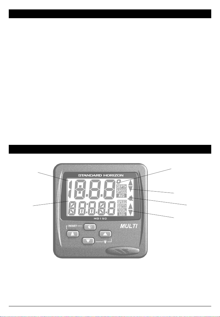
2 Controls and connections
Display is backlit for
Night Operation
Multi-function
display
Figure 1. MD150 Front Panel
Owner’s Manual
Sea temperature
Depth/speed
trend indicators
Alarm
Indicator
Depth/speed
trend indicators
MD150 User ManualPage 4

3 Accessories
3.1 Optional
SIA51 ........................................................................................ Transom Mount Impeller with 30-foot cable
SIA53 ....................................................................................................................... Thru-hull Speed Impeller
EX345 ........................................................................................................ 15-foot Impeller Extension Cable
EX345D ................................................................................................ 15-foot Transducer Extension Cable
DST50 .............................................................................................................. 2 inch low profile Transducer
DST51 ................................................................................................................ Transom Mount Transducer
DST52 ............................................................................................. Bronze Long Stem Thru-hull Transducer
DST53 .................................................................................................. 2 inch Bronze low profile Transducer
DST55 ..................................................................................................................... In-hull Depth Transducer
FB52 ........................................................................................................................ Fairing block for DST52
3.2 Replacement Parts
The following parts may be ordered from the STANDARD HORIZON Parts Department.
To order, call: 562-404-2700 Ext 351
Part ........................................................................................................................................... Part Number
Dummy Plug, SIA53 .................................................................................................................. 356002017A
Dust Cover ..........................................................................................................................................DC150
Flapper Valve, SIA53 ................................................................................................................. 596001019A
Paddlewheel Repair Kit, SIA51 .................................................................................................. 602002022A
Paddlewheel Repair Kit, SIA53 .................................................................................................. 602005009A
Thru-hull Fitting, SIA53 .............................................................................................................. 590170123A
Impeller Nut, SIA53 .................................................................................................................... 590170123A
Panel Gasket .............................................................................................................................. 108013023A
SIA53 / DST50 Mounting Nut ..................................................................................................... 580001027A
DST51 Mounting Bracket ........................................................................................................... 160001022A
SIA51 Mounting Bracket .............................................................................................................. 16002022A
4 Installation
4.1 Location
The MD150 is designed for above or below deck
installation. Select a position that is:
• At least 12 inches (300mm) from a compass
• At least 20 inches (500mm) from any radio
• Easy to read by the helmsman and crew
• Protected from physical damage
• Accessible to electrical cable connections
4.2 Mounting
The mounting surface must be flat. Use the template
to set the center of the fixing hole.
1 Drill a 1.25" (32mm) diameter mounting hole
through the bulkhead.
2 Remove the nut. Peel the protective paper
off the foam gasket and attach the gasket to
the rear of the instrument.
3 Insert the instrument through the bulkhead.
Hand tighten the nut, do not over tighten so
that the water sealing ability of the gasket is
damaged.
MD150 User Manual Page 5
Owner’s Manual
 Loading...