

Page 1

MATRIX SERIES
GX2000 and GX2100
25 Watt VHF/FM
Marine Transceivers
Owner's Manual
Integrated dual channel AIS (Automatic Identification System) receiver (GX2100)
AIS (Automatic Identification System) receiver or transponder connection (GX2000)
AIS target display: MMSI. Call Sign, Ship Name, BRG, DST, SOG, and COG
Contact AIS Ship with DSC*
38400 AIS VDM sentence output to compatible GPS Chart Plotter (GX2100)
80 dB Commercial grade receiver
Class D DSC (Digital Selective Calling) with Individual, All Ship, Position Report, Posi-
tion Request, and Distress.
Automatically poll up to 4 ships
Independent Channel 70 receiver built-in for continuous DSC watch
Local/Distance attenuator
Enter, Save, and Navigation to waypoint with Compass page
Navigation to a DSC Distress Call
Submersible JIS-7 / IPX7 (3.3 feet for 30 minutes)
ClearVoice noise canceling speaker microphone with channel selection and 16/9 key
Oversized rotary channel knob with push to enter, backlit display and keys
30 Watt PA/Loud Hailer with pre-programmed fog signals and (listen back GX2100)
Capable of connecting an optional RAM3 second station remote microphone
Intercom between radio and RAM3
DSC position request and report function when connected to compatible GPS chart
plotter
Voice Scrambler (optional)
One button access to Channel 16 and 9
User programmable soft keys
Navigation (LAT/LON, SOG, and COG) information shown on display
E2O (Easy-To-Operate) menu system
When connected to an optional GPS (GX2100)
When connected to an optional GPS and AIS receiver or transponder (GX2000)
MATRIX AIS GX2100 MATRIX GX2000
Page 1GX2000/GX2100
Page 2

TABLE OF CONTENTS
Quick Reference Guide ................................................................................................................................................. 4
1 GENERAL INFORMATION..................................................................................................................................... 8
2 PACKING LIST ....................................................................................................................................................... 9
3 OPTIONS ................................................................................................................................................................. 9
4 SAFETY/WARNING INFORMATION .................................................................................................................... 10
5 FCC RADIO LICENSE INFORMATION ............................................................................................................. 11
6 FCC NOTICE ........................................................................................................................................................ 12
7 GETTING STARTED ............................................................................................................................................ 13
7.1 PROHIBITED COMMUNICATION .......................................................................................................... 13
7.2 ABOUT VHF RADIO .............................................................................................................................. 13
7.3 SELECTING AN ANTENNA ................................................................................................................... 13
7.4 COAXIAL CABLE .................................................................................................................................... 14
7.5 EMERGENCY (CHANNEL 16 USE) ........................................................................................................ 15
7.6 CALLING ANOTHER VESSEL (CHANNEL 16 OR 9) ........................................................................... 16
7.7 MAKING TELEPHONE CALLS .............................................................................................................. 17
7.8 OPERATING ON CHANNELS 13 AND 67 .........................................................................................17
8 INSTALLATION ..................................................................................................................................................... 18
8.1 LOCATION ............................................................................................................................................... 18
8.2 MOUNTING THE RADIO ....................................................................................................................... 18
8.3 ELECTRICAL CONNECTIONS .............................................................................................................. 20
8.4 ACCESSORY CABLE ............................................................................................................................. 21
8.5 CHECKING GPS CONNECTIONS ........................................................................................................ 23
8.6 CHANGING THE GPS TIME ................................................................................................................ 23
8.7 CHANGING THE TIME LOCATION...................................................................................................... 24
8.8 CHANGING THE TIME FORMAT ......................................................................................................... 24
8.9 CHANGING COG TO TRUE OR MAGNETIC .................................................................................... 25
8.10 OPTIONAL CMP30 (RAM3) INSTALLATION .......................................................................................... 26
9 CONTROLS AND INDICATORS ......................................................................................................................... 28
9.1 CONTROLS AND CONNECTIONS ....................................................................................................... 28
10 BASIC OPERATION ............................................................................................................................................. 33
10.1 RECEPTION ............................................................................................................................................ 33
10.2 TRANSMISSION ..................................................................................................................................... 33
10.3 TRANSMIT TIME-OUT TIMER (TOT) ................................................................................................... 33
10.4 SIMPLEX/DUPLEX CHANNEL USE ..................................................................................................... 34
10.5 DISPLAY TYPE ....................................................................................................................................... 34
10.6 USA, CANADA, AND INTERNATIONAL MODE .................................................................................... 35
10.7 NOAA WEATHER CHANNELS ............................................................................................................. 35
10.8 DUAL WATCH (TO CHANNEL16) .......................................................................................................... 36
10.9 SCANNING .............................................................................................................................................. 37
10.10 PRESET CHANNELS (0 ~ 9): INSTANT ACCESS .............................................................................. 39
10.11 PA/FOG OPERATION ............................................................................................................................. 40
10.12 INTERCOM OPERATION ....................................................................................................................... 43
10.13 VOICE SCRAMBLER ............................................................................................................................. 44
11 DIGITAL SELECTIVE CALLING ......................................................................................................................... 45
11.1 GENERAL ................................................................................................................................................ 45
11.2 MARITIME MOBILE SERVICE IDENTITY (MMSI) ............................................................................... 45
11.2.1 What is an MMSI? ............................................................................................................... 45
11.2.2 Programming the MMSI ........................................................................................................ 46
11.3 DSC DISTRESS CALL .......................................................................................................................... 47
11.3.1 Transmitting a DSC Distress Call ....................................................................................... 47
11.3.2 Receiving a DSC Distress Call ........................................................................................... 50
11.4 ALL SHIPS CALL ................................................................................................................................... 52
11.4.1 Transmitting an All Ships Call ............................................................................................. 52
11.4.2 Receiving an All Ships Call ................................................................................................. 53
11.5 INDIVIDUAL CALL .................................................................................................................................. 54
11.5.1 Setting up the Individual / Position Call Directory .............................................................. 54
11.5.2 Setting up Individual Reply .................................................................................................. 55
11.5.3 Enabling the Individual Acknowledgment ............................................................................ 55
11.5.4 Setting up Individual / Group Call Ringer ........................................................................... 56
11.5.5 Transmitting an Individual Call ............................................................................................ 57
11.5.5 Receiving an Individual Call ................................................................................................ 59
11.6 DSC LOG OPERATION ......................................................................................................................... 60
11.6.1 Reviewing and Relaying a Logged DSC Distress Call .................................................... 60
11.6.2 Reviewing a Logged All Ship or Individual Call ............................................................... 61
11.6.3 Deleting a Call from the "DSC LOG" Directory ................................................................ 62
11.7 GROUP CALL ......................................................................................................................................... 63
11.7.1 Setting up a Group Call ...................................................................................................... 63
11.7.2 Transmitting a Group Call .................................................................................................... 64
11.7.3 Receiving a Group Call ........................................................................................................ 66
1. Accepting to auto switching to channel 16 .......................................................................... 50
2. Pausing the auto switching to channel 16 .......................................................................... 50
3. Quit to exit to the working channel ..................................................................................... 50
1. Accepting to auto switching to channel 16 .......................................................................... 53
2. Pausing the auto switching to channel 16 .......................................................................... 53
3. Quit to exit to the working channel ..................................................................................... 53
GX2000/GX2100Page 2
Page 3

TABLE OF CONTENTS
11.8 POSITION REQUEST ............................................................................................................................ 67
11.8.1 Setting up a Position Reply ................................................................................................. 67
11.8.2 Setting up a Position Request Ringer ................................................................................ 68
11.8.3 Transmitting a Position Request to Another Vessel .......................................................... 68
11.8.4 Receiving a Position Request .............................................................................................. 69
11.9 POSITION REPORT ............................................................................................................................... 71
11.9.1 Setting up a DSC Position Report Ringer ......................................................................... 71
11.9.2 Transmitting a DSC Position Report Call .......................................................................... 71
11.9.3 Receiving a DSC Position Report Call .............................................................................. 73
11.9.4 Navigating to a Position Report .......................................................................................... 73
11.10 MANUAL INPUTTING OF THE GPS LOCATION (LAT/LON) ............................................................ 75
11.11 AUTO DSC POLLING .............................................................................................................................. 76
11.11.1 Selecting Stations to be Automatically Polled (tracked) .................................................... 76
11.12.2 Enable/Disable Auto DSC Polling ........................................................................................ 77
11.12 DSC TEST .............................................................................................................................................. 78
11.12.1 Programming MMSI into Individual Directory ..................................................................... 78
11.12.2 DSC Test Call by using Individual Directory ..................................................................... 78
12 GENERAL SETUP ................................................................................................................................................ 80
13 CHANNEL FUNCTION SETUP ........................................................................................................................... 89
14 DSC SETUP ......................................................................................................................................................... 96
15 AIS / COMPASS SETUP .................................................................................................................................... 102
16 WAYPOINTS ........................................................................................................................................................ 108
17 CMP30 (RAM3) REMOTE MIC OPERATION ................................................................................................. 114
18 MAINTENANCE ................................................................................................................................................... 118
19 CHANNEL ASSIGNMENTS ............................................................................................................................... 120
20 WARRANTY ........................................................................................................................................................ 126
21 RESET PROCEDURES ...................................................................................................................................... 129
22 SPECIFICATIONS ............................................................................................................................................... 130
11.12.3 DSC Test Call by Manually Entering MMSI ....................................................................... 79
12.1 DISPLAY .................................................................................................................................................. 80
12.2 LOCAL DISTANCE RECEIVER ATTENUATOR ................................................................................... 81
12.3 LAMP ADJUSTING ................................................................................................................................. 82
12.4 DISPLAY CONTRAST ............................................................................................................................ 82
12.5 TIME OFFSET ........................................................................................................................................ 83
12.6 TIME AREA ............................................................................................................................................. 84
12.7 TIME DISPLAY ....................................................................................................................................... 84
12.8 UNIT OF MEASURE .............................................................................................................................. 85
12.9 MAGNETIC .............................................................................................................................................. 86
12.10 KEY BEEP .............................................................................................................................................. 86
12.11 FOG ALERT TONE FREQUENCY ....................................................................................................... 87
12.12 SOFT KEYS ............................................................................................................................................ 88
13.1 CHANNEL GROUP ................................................................................................................................. 89
13.2 SCAN MEMORY ..................................................................................................................................... 89
13.3 SCAN TYPE ............................................................................................................................................ 90
13.4 SCAN RESUME ...................................................................................................................................... 90
13.5 PRIORITY CHANNEL ............................................................................................................................. 91
13.6 WEATHER ALERT .................................................................................................................................. 91
13.7 CHANNEL NAME ................................................................................................................................... 92
13.8 STATION NAME ..................................................................................................................................... 93
13.9 SCRAMBLER SETUP ............................................................................................................................. 94
13.10 DEMO MODE ......................................................................................................................................... 95
14.1 INDIVIDUAL DIRECTORY ...................................................................................................................... 96
14.2 INDIVIDUAL REPLY ............................................................................................................................... 97
14.3 INDIVIDUAL ACKNOWLEDGMENT ....................................................................................................... 97
14.4 INDIVIDUAL RINGER ............................................................................................................................. 98
14.5 GROUP DIRECTORY ............................................................................................................................. 98
14.6 POSITION REPLY ................................................................................................................................ 100
14.7 DSC BEEP ............................................................................................................................................ 101
15.1 AUTOMATIC IDENTIFICATION SYSTEM (AIS) ................................................................................. 102
15.2 DIRECTION ........................................................................................................................................... 103
15.3 ACTIVATION RANGE ........................................................................................................................... 103
15.4 CPA ALARM .......................................................................................................................................... 104
15.5 TCPA ALARM ........................................................................................................................................ 104
15.6 DISPLAY RANGE ................................................................................................................................. 105
15.7 AIS OPERATION .................................................................................................................................. 106
15.8 AIS RANGE .......................................................................................................................................... 107
16.1 MARKING A POSITION ....................................................................................................................... 108
16.2 ADDING A WAYPOINT ........................................................................................................................ 109
16.3 EDITING A WAYPOINT ....................................................................................................................... 110
16.4 DELETING A WAYPOINT .................................................................................................................... 110
16.5 SAVING A DSC POSITION CALL AS A WAYPOINT ...................................................................... 111
16.6 NAVIGATING TO A SAVED WAYPOINT ............................................................................................ 111
16.7 STOP NAVIGATING TO A WAYPOINT .............................................................................................. 112
17.1 REMOTE MIC CONTROLS ................................................................................................................ 114
17.2 ASSIGNING SOFT KEYS ................................................................................................................... 116
18.1 REPLACEMENT PARTS ...................................................................................................................... 118
18.2 FACTORY SERVICE ............................................................................................................................ 118
18.3 TROUBLESHOOTING CHART ............................................................................................................ 119
Page 3GX2000/GX2100
Page 4
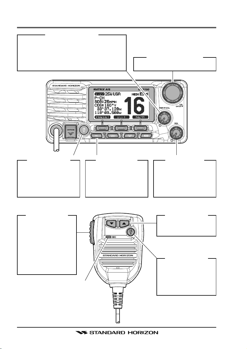
QUICK REFERENCE GUIDE
[
PWR/VOL] K
Press and hold this knob to turn on or off
the radio. When the radio is on, turning
this knob will adjust the speaker audio
volume.
NOB
[
CH/ENTER] K
Selects the operating channel.
NOB
[
16/9] B
Press to recall chan-
nel 16.
Press and hold to
recall channel 9.
[
PTT] S
Place your mouth
about 1/2 inch away
from Mic hole and
speak in a normal
voice level while
pressing this
switch.
UTTON
WITCH
[
H/L] B
When pressed,
toggles the transmit
power between High
(25W) and Low (1W).
MIC H
OLE
UTTON
[
SQL] K
Move this control
clockwise to squelch
or counter clockwise
un-squelch the radio.
[]
Selects the operating
channel.
[
16/9] B
Press to recall
channel 16.
Press and hold to
recall channel 9.
NOB
/ [] K
UTTON
EY
GX2000/GX2100Page 4
Page 5
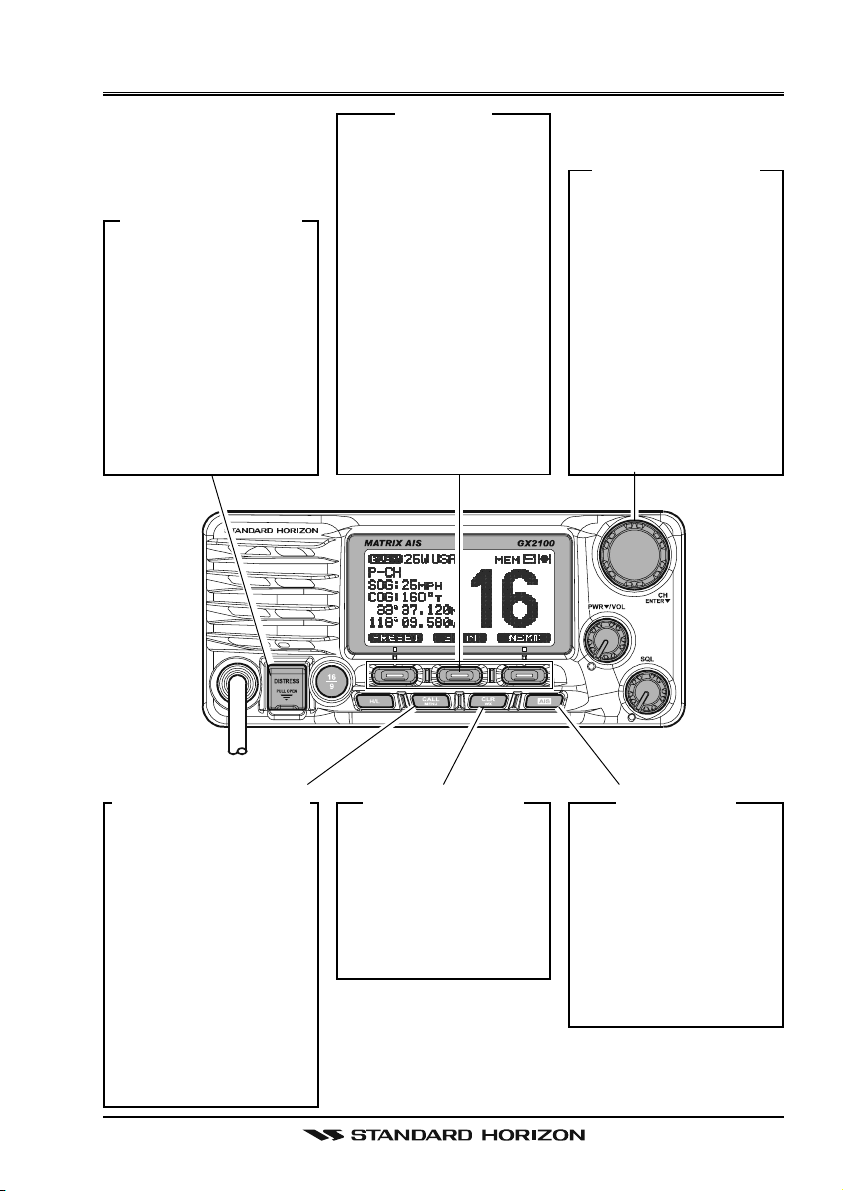
QUICK REFERENCE GUIDE
[
DISTRESS] B
Note: for this key to
operate a MMSI must
be programmed.
To transmit a DSC Distress call, lift the red
cover, press the Distress button once,
then press and hold
until the radio alarms.
UTTON
[
]
S
OFT
K
EY
The 3 soft keys underneath the display can
be customized, refer
to section “12.12
SOFT KEYS”.
The factory defaults
are Key 1: [PRESET], 2:
[
SCAN], and 3: [NEXT
key. Pressing the
[
NEXT] soft key will
show Key 1: [DW],
Key 2: [PA/FOG], Key
3: [NEXT].
[
CH/ENTER] K
Selects a Marine
VHF or NOAA
weather channel.
Selects the item in
]
the “SETUP MENU”
and “DSC MENU”.
When the “SETUP
MENU” or “DSC
MENU” is selected,
pressing this knob
enters a selection.
NOB
[
CALL/MENU] B
Press to access the
“DSC MENU”, refer
to section “11 DIGI-
TAL SELECTIVE
CALLING”.
Press and hold to
access the “SETUP
MENU”, refer to
section “12 GEN-
ERAL SETUP
MODE”.
UTTON
[
CLR/WX] B
Press to cancel a
menu selection.
Press and hold to
recall the last-used
NOAA Weather
Channel.
UTTON
[
AIS] B
UTTON
Press to change the
display to AIS (Automatic Identification
System) mode.
To setup AIS features,
refer to section “15
AIS / COMPASS
SETUP”.
Page 5GX2000/GX2100
Page 6
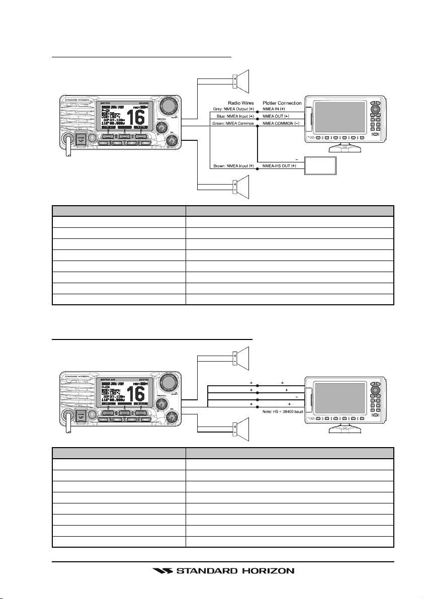
ELECTRICAL CONNECTIONS
Red
Shield
Whit e
Shield
PA Speak er
NMEA COMMON
External Speaker
MATRIX GX2000
Red
Shield
Gray: NMEA Output
Blue: NMEA Input
Green: NMEA Common
Brown: NMEA Input
Whit e
Shield
Radio Wi res
PA Speak er
Plotter Connection
( )
NMEA IN
( )
NMEA OUT
NMEA COMMON
( )
NMEA-HS OUT
External Speaker
MATRIX AIS GX2100
( )
( )
( )
AIS Receiver
Note: HS = 38400 baud
( )
( )
GPS Receiver
GPS Receiver
GX2000/GX2100Page 6
Page 7
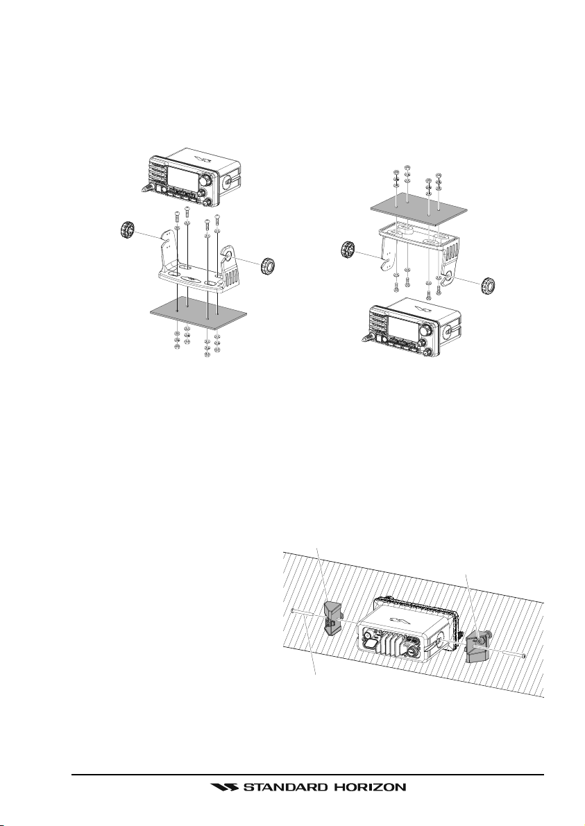
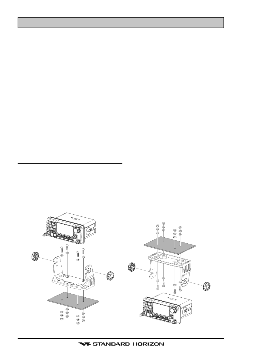
DESKTOP/OVERHEAD MOUNTING THE RADIO
The supplied universal mounting bracket allows desktop or overhead mounting.
Use a 13/64” (5.2-mm) bit to drill the holes to a surface which is more 0.4 inch
(10 mm) thick and can support more than 3.3 lbs (1.5 kg) and secure the
bracket with the supplied screws, spring washers, flat washers, and nuts.
DESKTOP MOUNTING OVERHEAD MOUNTING
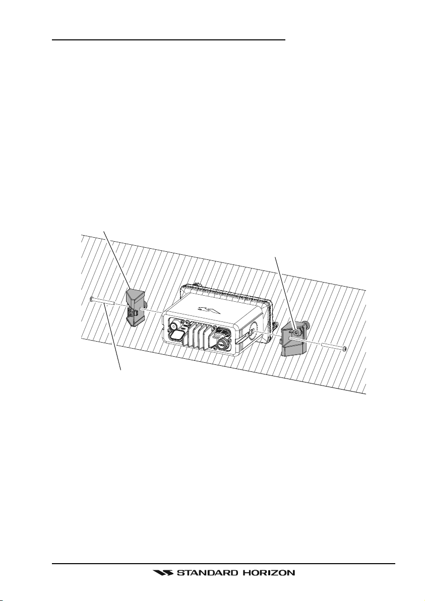
FLUSH MOUNTING THE RADIO
The optional MMB-84 Flush-Mount Bracket allows flush mounting the radio on
your vessel.
1. Use the supplied template to mark the location where the rectangular hole
is to be cut. Confirm the space behind the dash or panel is deep enough to
accommodate the transceiver (at least 6.7 inches (17 cm) deep).
There should be at least 1/2
Bracket
inch (1.3 cm) between the
transceiver’s heatsink and any
Adjusting Screw
wiring, cables or structures.
2. Cut out the rectangular hole
and insert the transceiver.
3. Fasten the optional MMB-84
brackets to the sides of the
transceiver with the lock
Lock-washer screw combination
washer screw combination; so
that the mounting screw base faces the mounting surface.
4. Turn the adjusting screw on each bracket to adjust the tension so that the
transceiver is tight against the mounting surface.
Page 7GX2000/GX2100
Page 8

1 GENERAL INFORMATION
1.1 INTRODUCTION
The STANDARD HORIZON MATRIX Series GX2000 and GX2100 Marine VHF/
FM Marine transceiver are designed to be used in USA, International and Canadian Marine bands. The GX2000 and GX2100 can be operated from 11 to
16 VDC and has a switchable RF output power of 1 watt or 25 watts.
MATRIX AIS GX2100
Integrates a dual channel AIS (Automatic Identification System) receiver to
display AIS vessel information (MMSI, Call Sign, Ship Name, BRG, DST, SOG
and COG) directly on the VHF radio, so you will know what is out there in any
conditions. The GX2100 is also capable of entering and saving up to 100
waypoints, which may be selected and navigated to by using a unique navigation compass display. The MATRIX AIS allows you to contact an AIS Ship
directly using DSC, show your vessels position in relation to AIS targets and
alert you when an AIS ship may be approaching too close to your location via
the Closest Point of Approach (CPA) Alarm. To receive AIS targets from ships
with AIS class A or B transponders, simply connect the normal VHF antenna
(only one antenna needed!)
MATRIX - GX2000
For the mariner who already has AIS on-board and desires a VHF with the
features of the MATRIX AIS, the MATRIX GX2000 has a connection for an AIS
receiver or transponder.
The MATRIX Series VHF’s are capable of DSC (Digital Selective Calling) Class
D operation. Class D operation allows continuous receiving of Digital Selective
Calling functions on channel 70 even if the radio is receiving a call. The MATRIX Series VHF's operate on all currently-allocated marine channels which
are switchable for use with USA, International, or Canadian regulations. Emergency channel 16 can be immediately selected from any channel by pressing
the red [16/9] key. NOAA Weather channels can also be accessed immediately by pressing and holding the [CLR(WX)] key.
Other features of the MATRIX Series VHF’s include: Speaker Microphone,
30W PA/Fog, optional RAM3 second station remote-control microphone with
display, intercom between radio and optional RAM3, scanning, priority scanning, submersible speaker mic, high and low voltage warning, and GPS repeatability.
GX2000/GX2100Page 8
Page 9

2 PACKING LIST
When the package containing the transceiver is first opened, please check it
for the following contents:
GX2000 or GX2100 Transceiver
Mounting Bracket and hardware
Owner’s Manual
DSC Warning Sticker
Flush Mount Template
Power Cord
3 OPTIONS
MMB-84 .........................................................................Flush-Mount Bracket
CMP30B/W ............... Remote-Access Microphone (RAM3 Mic, Black/White)
CT-100 ............................................... 23-foot Extension Cable for RAM3 Mic
CVS2500 ...............................................................................Voice Scrambler
MLS-310 ............ 10W amplified External Speaker with on/off Volume control
MLS-300 .................................................................... External Loud Speaker
220SW ..................................................................... 4.5” Round Hail/PA Horn
240SW ........................................................ 5” x 8” Rectangular Hail/PA Horn
Page 9GX2000/GX2100
Page 10

4 SAFETY / WARNING INFORMATION
This radio is restricted to occupational use, work related operations only where
the radio operator must have the knowledge to control the exposure conditions of its passengers and bystanders by maintaining the minimum separation distance of 0.89 m (2.92 feet). Failure to observe these restrictions will
result in exceeding the FCC RF exposure limits.
Antenna Installation:
The antenna must be located at least 0.89 m (about 3 feet) away from passengers in order to comply with the FCC RF exposure requirements.
ON-LINE WARRANTY REGISTRATION (in USA or Canada only)
Please visit www.standardhorizon.com to register the GX2000/GX2100
Marine VHF. It should be noted that visiting the Web site from time to
time may be beneficial to you, as new products are released they will
appear on the STANDARD HORIZON Web site.
PRODUCT SUPPORT INQUIRIES
If you have any questions or comments regarding the use of the GX2000/
GX2100, you can visit the STANDARD HORIZON Web site to send an
E-Mail or contact the Product Support team at (800) 767-2450 M-F 7:005:00PST.
GX2000/GX2100Page 10
Page 11

5 FCC RADIO LICENSE INFORMATION
Standard Horizon radios comply with the Federal Communication Commission (FCC) requirements that regulate the Maritime Radio Service.
5.1 STATION LICENSE
An FCC ship station license is no longer required for any vessel traveling in
U.S. waters (except Hawaii) which is under 20 meters in length. However, any
vessel required to carry a marine radio on an international voyage, carrying a
HF single side band radiotelephone or marine satellite terminal is required to
have a ship station license. FCC license forms, including applications for ship
(605) and land station licenses can be downloaded via the Internet at http://
www.fcc.gov/Forms/Form605/605.html. To obtain a form from the FCC, call
(888) 225-5322.
5.2 RADIO CALL SIGN
Currently the FCC does not require recreational boaters to have a Ship Radio
Station License. The USCG recommends the boats registration number and
the state to be used when calling another vessel.
5.3 CANADIAN SHIP STATION LICENSING
You may need a license when traveling in Canada. If you do need a license
contact their nearest field office or regional office or write:
Industry Canada
Radio Regulatory Branch
Attn: DOSP
300 Slater Street
Ottawa, Ontario
Canada, KIA 0C8
5.4 FCC / INDUSTRY CANADA INFORMATION
The following data pertaining to the transceiver is necessary to fill out the license application.
Type Acceptance ......................................................................... FCC Part 80
Output Power ............................................... 1 Watt (low) and 25 Watts (high)
Emission ......................................................................... 16K0G3E, 16K0G2B
Frequency Range .................................................... 156.025 to 163.275 MHz
FCC Type Number .................................................................. K6630443X3D
Industry Canada Type Approval ............................................ 511B-30443X3S
Page 11GX2000/GX2100
Page 12

6 FCC NOTICE
NOTICE
Unauthorized changes or modifications to this equipment may void compliance with FCC Rules. Any change or modification must be approved
in writing by STANDARD HORIZON.
NOTICE
This equipment has been tested and found to comply with the limits for
a Class B digital device, pursuant to Part 15 of the FCC Rules. These
limits are designed to provide reasonable protection against harmful
interference in a residential installation. This equipment generates, uses
and can radiate radio frequency energy and, if not installed and used in
accordance with the instructions, may cause harmful interference to radio communications. However, there is no guarantee that interference
will not occur in a particular installation. If this equipment does cause
harmful interference to radio or television reception, which can be determined by turning the equipment off and on, the user is encouraged to
try to correct the interference by one or more of the following measures:
- Reorient or relocate the receiving antenna.
- Increase the separation between the equipment and receiver.
- Connect the equipment into an outlet on a circuit different from that to
which the receiver is connected.
- Consult the dealer or an experienced radio/TV technician for help.
NOTE
The MATRIX AIS GX2100 does not require a special marine VHF antenna to receive AIS transmissions. The MATRIX AIS does not transmit
AIS signals, it is NOT recommended to use an antenna dedicated for
AIS operation.
What is the range for AIS receivers?
Since AIS uses similar frequencies as a marine VHF radio, it has similar radio
reception capabilities - which are basically line of sight. This means that the
higher the VHF antenna is mounted, the greater the reception area will be.
Reception from Class A vessels that are 20 or even 30 miles away on open
water is not uncommon as their antennas are mounted high off the water.
Class B transponders use lower power for transmissions; therefore you can
expect Class B vessels to be acquired when they are 5 to 10 miles away.
GX2000/GX2100Page 12
Page 13

7 GETTING STARTED
7.1 PROHIBITED COMMUNICATIONS
The FCC prohibits the following communications:
• False distress or emergency messages:
• Messages to “any boat” except in emergencies and radio tests;
• Messages to or from a vessel on land;
• Transmission while on land;
• Obscene, indecent, or profane language (potential fine of $10,000).
7.2 ABOUT VHF RADIO
The radio frequencies used in the VHF marine band lie between 156 and 158
MHz with some shore stations available between 161 and 163 MHz. The marine VHF band provides communications over distances that are essentially
“line of sight” (VHF signals do not travel well through objects such as buildings,
hills or trees). Actual transmission range depends much more on antenna type,
gain and height than on the power output of the transmitter. On a fixed mount
25W radio transmission expected distances can be greater than 15 miles, for
a portable 5W radio transmission the expected distance can be greater than 5
miles in “line of sight”.
7.3 SELECTING AN ANTENNA
Marine antennas are made to radiate signals equally in all horizontal directions, but not straight up. The objective of a marine antenna is to enhance the
signal toward the horizon. The degree to which this is accomplished is called
the antenna’s gain. It is measured in decibels (dB) and is one of the major
factors in choosing an antenna. In terms of effective radiated power (ERP),
antennas are rated on the basis of how much gain they have over a theoretical
antenna with zero gain. A 3 foot, 3dB gain antenna represents twice as much
gain over the imaginary antenna.
Typically a 3 foot 3dB gain stainless steel whip is used on a sailboat mast. The
longer 8 foot 6dB fiberglass whip is primarily used on power boats that require
the additional gain.
Page 13GX2000/GX2100
Page 14
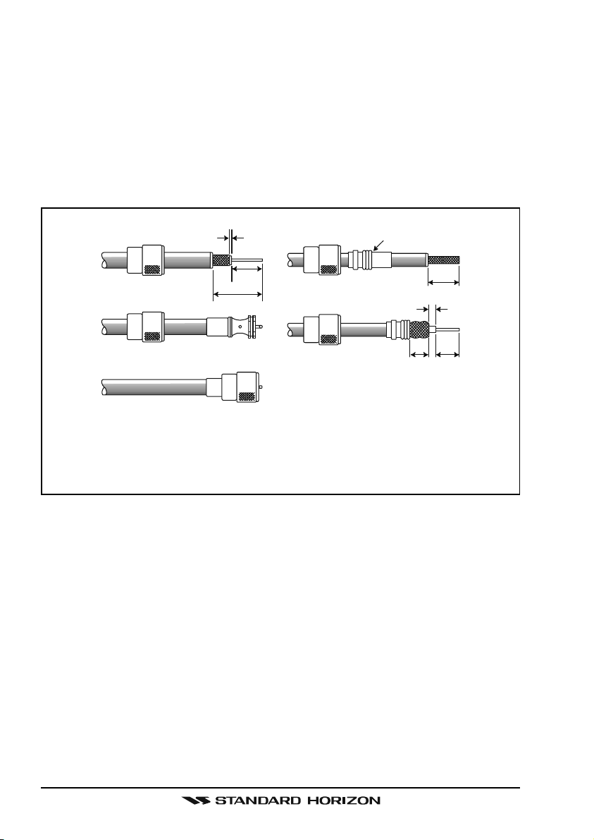
7.4 COAXIAL CABLE
VHF antennas are connected to the transceiver by means of a coaxial cable –
a shielded transmission line. Coaxial cable is specified by it’s diameter and
construction.
For runs less than 20 feet, RG-58/U, about 1/4 inch in diameter is a good
choice. For runs over 20 feet but less than 50 feet, the larger RG-8X or RG213/U should be used for cable runs over 50 feet RG-8X should be used. For
installation of the connector onto the coaxial cable refer to the figure below.
1/16''
3/4''
1 1/8''
Adapter
3/4''
1/8''
5/8''3/8''
To get your coax cable through a fitting and into your boat’s interior, you
may have to cut off the end plug and reattach it later. You can do this if
you follow the directions that come with the connector. Be sure to make
good soldered connections.
GX2000/GX2100Page 14
Page 15

7.5 EMERGENCY (CHANNEL 16 USE
Channel 16 is known as the Hail and Distress Channel. An emergency may be
defined as a threat to life or property. In such instances, be sure the transceiver
is on and set to CHANNEL 16. Then use the following procedure:
1. Press the microphone push-to-talk switch and say “Mayday, Mayday, May-
day. This is , , ” (your vessel’s name).
2. Then repeat once: “Mayday, ” (your vessel’s name).
3. Now report your position in latitude/longitude, or by giving a true or magnetic bearing (state which) to a well-known landmark such as a navigation
aid or geographic feature such as an island or harbor entry.
4. Explain the nature of your distress (sinking, collision, aground, fire, heart
attack, life-threatening injury, etc.).
5. State the kind of assistance your desire (pumps, medical aid, etc.).
6. Report the number of persons aboard and condition of any injured.
7. Estimate the present seaworthiness and condition of your vessel.
8. Give your vessel’s description: length, design (power or sail), color and
other distinguishing marks. The total transmission should not exceed 1
minute.
9. End the message by saying “OVER”. Release the microphone button and
listen.
10. If there is no answer, repeat the above procedure. If there is still no response, try another channel.
)
NOTE
The GX2000 and GX2100 have DSC Distress calling, that can transmit
a distress call digitally to all ships with compatible DSC radios. Refer to
section “11 DIGITAL SELECTIVE CALLING”.
Page 15GX2000/GX2100
Page 16

7.6 CALLING ANOTHER VESSEL (CHANNEL 16 OR 9
Channel 16 may be used for initial contact (hailing) with another vessel.
However, its most important use is for emergency messages. This channel
must be monitored at all times except when actually using another channel.
It is monitored by the U.S. and Canadian Coast Guards and by other vessels.
Use of channel 16 for hailing must be limited to initial contact only. Calling should not exceed 30 seconds, but may be repeated 3 times at 2-minute
intervals. In areas of heavy radio traffic, congestion on channel 16 resulting
from its use as a hailing channel can be reduced significantly in U.S. waters by
using channel 9 as the initial contact (hailing) channel for non-emergency
communications. Here, also, calling time should not exceed 30 seconds but
may be repeated 3 times at 2-minute intervals.
Prior to making contact with another vessel, refer to the channel charts in this
manual, and select an appropriate channel for communications after initial
contact. For example, Channels 68 and 69 of the U.S. VHF Charts are some of
the channels available to non-commercial (recreational) boaters. Monitor your
desired channel in advance to make sure you will not be interrupting other
traffic, and then go back to either channel 16 or 9 for your initial contact.
When the hailing channel (16 or 9) is clear, press the PTT button on the mic
and state the name of the other vessel you wish to call and then “this is”
followed by the name of your vessel and your Station License (Call Sign) then
release the PTT button on the mic. When the other vessel returns your call,
immediately request another channel by pressing the PTT button on the mic
and saying “go to,” the number of the other channel, say “over” and release
the PTT button on the mic. Then switch to the new channel. When the new
channel is not busy, call the other vessel.
)
After a transmission, say “over,” and release the microphone’s push-to-talk
(PTT) switch. When all communication with the other vessel is completed, end
the last transmission by stating your Call Sign and the word “out.” Note that it
is not necessary to state your Call Sign with each transmission, only at the
beginning and end of the contact.
Remember to return to Channel 16 when not using another channel. Some
radios automatically monitor Channel 16 even when set to other channels or
when scanning.
GX2000/GX2100Page 16
Page 17

7.7 MAKING TELEPHONE CALLS
To make a radiotelephone call, use a channel designated for this purpose, The
fastest way to learn which channels are used for radiotelephone traffic is to
ask at a local marina. Channels available for such traffic are designated Pub-
lic Correspondence channels on the channel charts in this manual. Some
examples for USA use are Channels 24, 25, 26, 27, 28, 84, 85, 86, and 87.
Call the marine operator and identify yourself by your vessel’s name, The marine
operator will then ask you how you will pay for the call (telephone credit card,
collect, etc.) and then link your radio transmission to the telephone lines.
The marine telephone company managing the VHF channel you are using
may charge a link-up fee in addition to the cost of the call.
7.8 OPERATING ON CHANNELS 13 AND 67
Channel 13 is used at docks and bridges and by vessels maneuvering in port.
Messages on this channel must concern navigation only, such as meeting and
passing in restricted waters.
Channel 67 is used for navigational traffic between vessels.
By regulation, power is normally limited to 1 Watt on these channels. Your
radio is programmed to automatically reduce power to this limit on these channels. However, in certain situations it may be necessary to temporarily use a
higher power. See page 30 ([H/L] key) for means to temporarily override the
low-power limit on these two channels.
Page 17GX2000/GX2100
Page 18
8 INSTALLATION
8.1 LOCATION
The radio can be mounted at any angle. Choose a mounting location that:
• is far enough from any compass to avoid any deviation in compass reading due to the speaker magnet
• provides accessibility to the front panel controls
• allows connection to a power source and an antenna
• has nearby space for installation of a microphone hanger
• choose a mounting location that is at least 3 feet (1 m) away from the
radio’s antenna.
Note: To insure the radio does not affect the compass or radios performance is
not affected by the antenna location, temporarily connect the radio in the desired location and:
a. Examine the compass to see if the radio causes any deviation
b. Connect the antenna and key the radio. Check to ensure the radio is
operating correctly by requesting a radio check.
8.2 MOUNTING THE RADIO
8.2.1 Supplied Mounting Bracket
The supplied mounting bracket allows overhead or desktop mounting.
Use a 13/64” (5.2-mm) bit to drill the holes to a surface which is more 0.4 inch
(10 mm) thick and can support more than 3.3 lbs (1.5 kg) and secure the
bracket with the supplied screws, spring washers, flat washers, and nuts.
DESKTOP MOUNTING OVERHEAD MOUNTING
GX2000/GX2100Page 18
Page 19
8.2.2 Optional MMB-84 Flush Mount Bracket
1. Make a rectangular template for the flush mount measuring 2.6” H x
6.3” W (65 x 161 mm).
2. Use the template to mark the location where the rectangular hole is to be
cut. Confirm the space behind the dash or panel is deep enough to accommodate the transceiver (at least 6.7 inches (17 cm) deep).
There should be at least 1/2 inch (1.3 cm) between the transceiver’s heatsink
and any wiring, cables or structures.
3. Cut out the rectangular hole and insert the transceiver.
4. Fasten the brackets to the sides of the transceiver with the lock washer
screw combination; so that the mounting screw base faces the mounting
surface (see illustration below).
5. Turn the adjusting screw to adjust the tension so that the transceiver is
tight against the mounting surface.
Bracket
Adjusting Screw
Lock-washer screw combination
Page 19GX2000/GX2100
Page 20
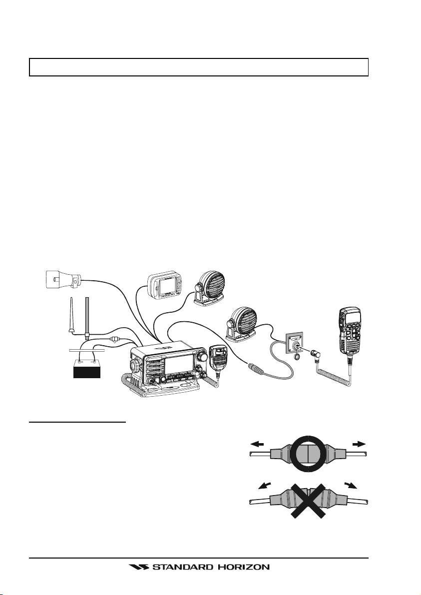
8.3 ELECTRICAL CONNECTIONS
CAUTION
Reverse polarity battery connections will damage the radio!
Connect the power cord and antenna to the radio. Antenna and Power Supply
connections are as follows:
1. Mount the antenna at least 3 feet (1 m) away from the radio. At the rear of
the radio, connect the antenna cable. The antenna cable must have a
PL259 connector attached. RG-8/U coaxial cable must be used if the antenna is 25 feet (7.6 m) or more from the radio. RG58 cable can be used
for distances less than 25 feet (7.6 m).
2. Connect the red power wire to a 13.8 VDC ±20% power source. Connect
the black power wire to a negative ground.
3. If an optional remote extension speaker is to be used, refer to section 8.4
for connections.
4. It is advisable to have a Certified Marine Technician check the power output and the standing wave ratio of the antenna after installation.
Optional HAIL/PA Horn
Antenna
A
c
c
e
s
Water proof
Deck Outlet
GPS Navigation Receiver
s
o
r
y
C
a
b
l
e
Fuse
Optional Speaker
Optional Speaker
Optional CMP30 Remote MIC
Red
Black
Power Source
Fuse Replacement
To take out the Fuse from the Fuse Holder, hold
both ends of the Fuse Holder and pull the Fuse
Holder apart without bending the fuse Holder.
When you replace the Fuse, please confirm that
the Fuse is tightly fixed on the metal contact located inside the Fuse Holder. If the metal contact
holding the fuse is loose, the Fuse holder may
heat up.
GX2000/GX2100Page 20
Page 21
8.4 ACCESSORY CABLE
8.4.1 MATRIX GX2000 Connection
Red
Shield
White
Shield
Wire Color/Description
WHITE - External Speaker (+
SHIELD - External Speaker
RED - PA Speaker (+
SHIELD - PA Speaker
)
(–)
GREEN - NMEA Ground
BLUE - NMEA GPS Input (+
GRAY - NMEA DSC Output (+
BROWN - AIS DATA Input (+
Connection Examples
)
Connect to external 4 Ohm audio speaker
(–)
Connect to external 4 Ohm audio speaker
Connect to external 4 Ohm PA speaker
Connect to external 4 Ohm PA speaker
Connect to NMEA
)
Connect to NMEA (+) output of GPS
)
Connect to NMEA (+) input of GPS
)
Connect to NMEA 38.4K baud (+) output of AIS receiver
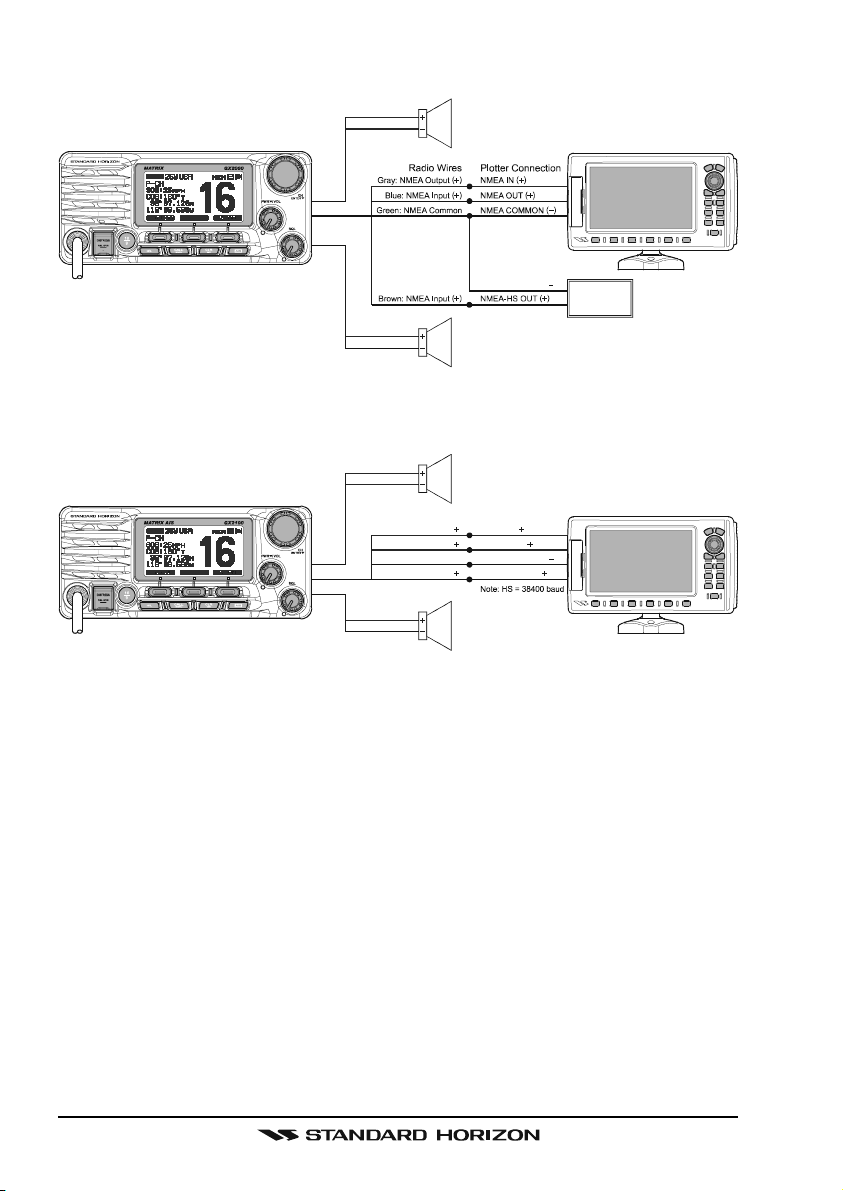
8.4.2 MATRIX AIS GX2100 Connection
Red
Shield
Gray: NMEA Output
Blue : NMEA Input
Green: NMEA Common
Brown: NMEA Output
PA Speaker
NMEA COMMON
External Speaker
(–)
connection of GPS
PA Speaker
Plotter ConnectionRadio Wires
( )
( )
( )
( )
NMEA IN
( )
NMEA OUT
NMEA COMMON
NMEA-HS IN
( )
( )
AIS Receiver
Note: HS = 38400 baud
( )
GPS Receiver
GPS Receiver
Wire Color/Description
WHITE - External Speaker (+
SHIELD - External Speaker
RED - PA Speaker (+
SHIELD - PA Speaker
(–)
)
(–)
GREEN - NMEA Ground
BLUE - NMEA GPS Input (+
)
GRAY - NMEA DSC Output (+
BROWN - AIS DATA Output (+
White
Shield
External Speaker
Connection Examples
)
Connect to external 4 Ohm audio speaker
Connect to external 4 Ohm audio speaker
Connect to external 4 Ohm PA speaker
Connect to external 4 Ohm PA speaker
Connect to NMEA
(–)
connection of GPS
Connect to NMEA (+) output of GPS
)
Connect to NMEA (+) input of GPS
)
Connect to NMEA 38.4K baud (+) input of GPS
Page 21GX2000/GX2100
Page 22
When connecting the external speaker or GPS navigation receiver, strip off
about 1 inch (2.5 cm) of the specified wire’s insulation, then splice the ends
together.
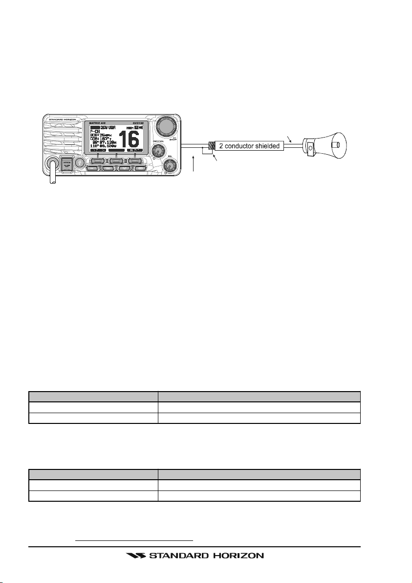
Note: In some areas powerful AM broadcast stations may be heard when in
listen-back mode. In this case change the speaker wire to 2-conductor shielded
audio cable. See the illustration below for connections.
Shield of cable is not
Red
Bare
Make Red and bare connecti ons short as possi bl e
attached on PA Speaker end
Connect the bare wire from the GX2000/GX2100
to one wire and to the shielded.
PA Speaker
GPS Connections (4800 baud)
NMEA INPUT (GPS Information)
• The GPS must have the NMEA Output turned on and set to 4800 Baud in
the setup menu. If there is a selection for parity select none.
• For further information on interfacing /setting up your GPS. Please contact
the manufacturer of the GPS receiver.
• GX2000/GX2100 can read NMEA-0183 version 2.0 or higher.
• The NMEA 0183 input sentences are GLL, GGA, RMC and GNS (RMC
sentence is recommended).
NMEA Output (DSC)
The NMEA 0183 output sentences are DSC and DSE.
AIS Connections (38400 baud only)
The MATRIX GX2000 (without internal AIS receiver) may be connected to an
external AIS receiver or transponder that outputs NMEA VDM sentence at
38400 baud.
Wire Color/Description
BROWN - AIS Input (+
)
GREEN - NMEA common
Connection
AIS Output
AIS common data wire or NMEA signal
(–)
The MATRIX AIS GX2100 with internal dual channel AIS receiver has the capability to output received Class A and B targets using VDM sentence at a
baud rate of 38400.
Wire Color/Description
BROWN - AIS Output (+
GREEN - NMEA common
)
Connection
GPS Chart plotter input
GPS common data wire or NMEA signal
(–)
If you have further inquires, please feel free to contact Product Support at:
Phone: (800) 767-2450
Email: marinetech@vxstdusa.com
GX2000/GX2100Page 22
Page 23
8.5 CHECKING GPS CONNECTIONS
After connections have been made between the
GX2000/GX2100 and the GPS, a small satellite icon
will appear on the top right corner of the display and
your current location (Latitude/Longitude) is shown on
the display.
NOTE
If there is a problem with the NMEA connection between the radio and
the GPS, the GPS icon will blink continuously until the connection is
corrected.
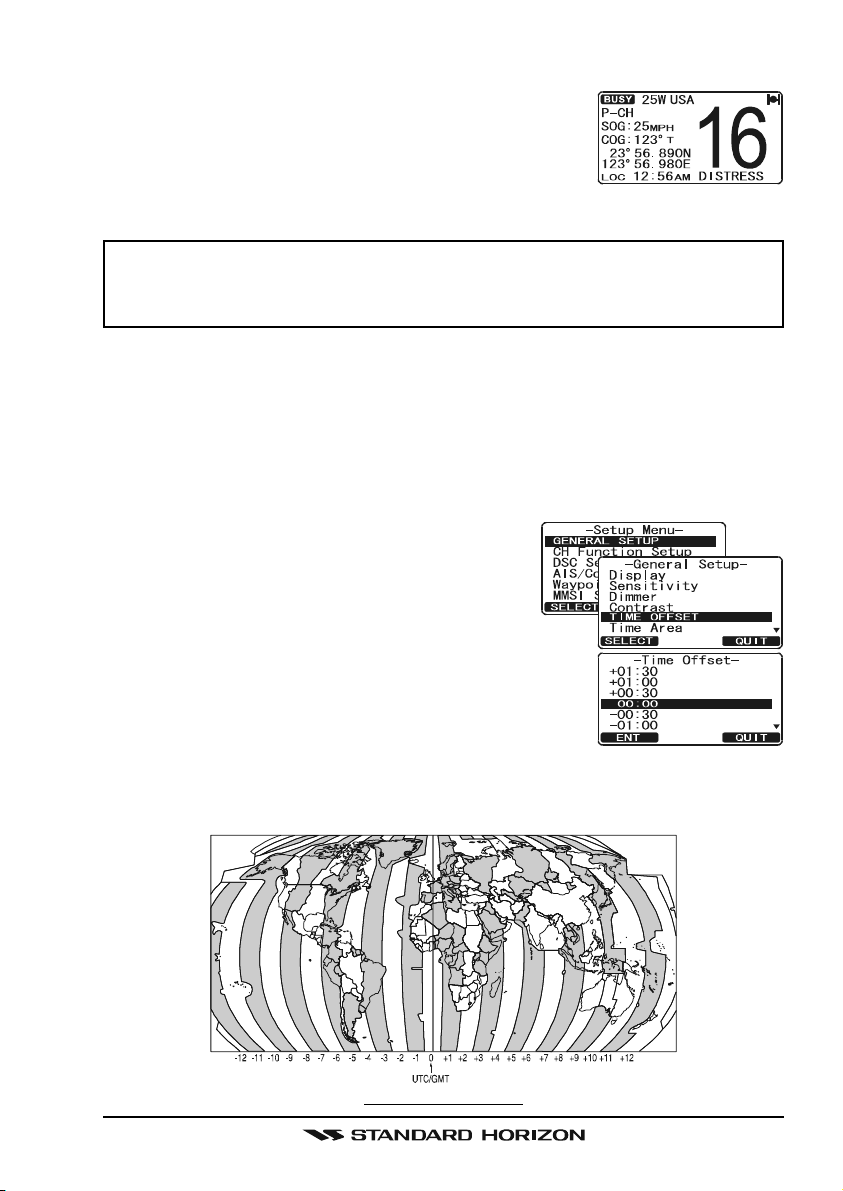
8.6 CHANGING THE GPS TIME
From the Factory the GX2000/GX2100 shows GPS satellite time or UTC time
when an optional GPS is connected. A time offset is needed to show the local
time in your area. The Time Offset must be changed in order for the radio to
display the current time in your area. Please see the Offset Time Table at the
bottom of this page.
1. Press and hold down the [CALL(MENU)] key
until “Setup Menu” appears, then select “GEN-
ERAL SETUP” with the CHANNEL knob.
2. Press the [SELECT] soft key, then select
“TIME OFFSET” with the CHANNEL knob.
3. Press the [SELECT] soft key, then rotate the CHAN-
NEL knob to select time offset of your location. See
illustration below to find your offset time. If “00:00”
is assigned, the time is the same as UTC (Universal
Time Coordinated or GPS Satellite Time).
4. Press the [ENT] soft key to store the time offset.
5. Press the [QUIT] soft key several times to return to radio operation.
OFFSET TIME TABLE
Page 23GX2000/GX2100
Page 24
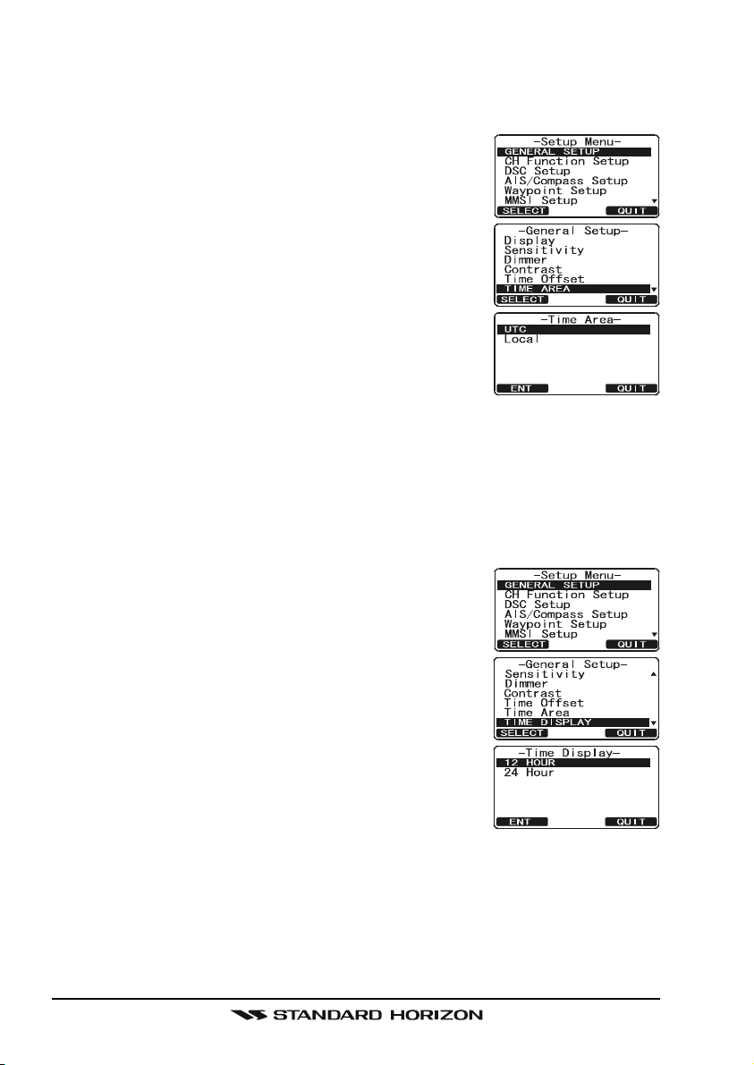
8.7 CHANGING THE TIME LOCATION
This menu selection allows the radio to show UTC time or local time with the
offset.
1. Press and hold down the [CALL(MENU)] key until
“Setup Menu” appears, then select “GENERAL SETUP”
with the CHANNEL knob.
2. Press the [SELECT] soft key, then rotate the CHAN-
NEL knob to “TIME AREA”.
3. Press the [SELECT] soft key.
4. Rotate the CHANNEL knob to select “UTC” or “LO-
CAL”.
5. Press the [ENT] soft key to store the selected setting.
6. Press the [QUIT] soft key several times to return to
radio operation.
8.8 CHANGING THE TIME FORMAT
This menu selection allows the radio to setup to show time in 12-hour or 24hour format.
1. Press and hold down the [CALL(MENU)] key until
“Setup Menu” appears, then select “GENERAL SETUP”
with the CHANNEL knob.
2. Press the [SELECT] soft key, then rotate the CHAN-
NEL knob to select “TIME DISPLAY”.
3. Press the [SELECT] soft key.
4. Rotate the CHANNEL knob to select “12 HOUR” or
“24 HOUR”.
5. Press the [ENT] soft key to store the selected setting.
6. Press the [QUIT] soft key several times to return to
radio operation.
GX2000/GX2100Page 24
Page 25
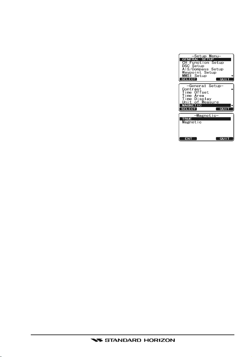
8.9 CHANGING COG TO TRUE OR MAGNETIC
Allows the GPS Course Over Ground to be selected to show in True or Magnetic. Factory default is True however by following the steps below the COG
can be changed to Magnetic.
1. Press and hold down the [CALL(MENU)] key until
“Setup Menu” appears, then select “GENERAL SETUP”
with the CHANNEL knob.
2. Press the [SELECT] soft key, then rotate the CHAN-
NEL knob to select “MAGNETIC”.
3. Press the [SELECT] soft key.
4. Rotate the CHANNEL knob to select “MAGNETIC”
or “TRUE”.
5. Press the [ENT] soft key to store the selected setting.
6. Press the [QUIT] soft key several times to return to
radio operation.
Page 25GX2000/GX2100
Page 26
8.10 OPTIONAL CMP30 (RAM3) INSTALLATION
The GX2000/GX2100 is capable of using a CMP30 (RAM3) Remote Station
Microphone to remotely control the Radio, AIS, DSC and PA/Fog functions. In
addition the GX2000/GX2100 can operate as a full function intercom system
between the RAM3 and the radio.
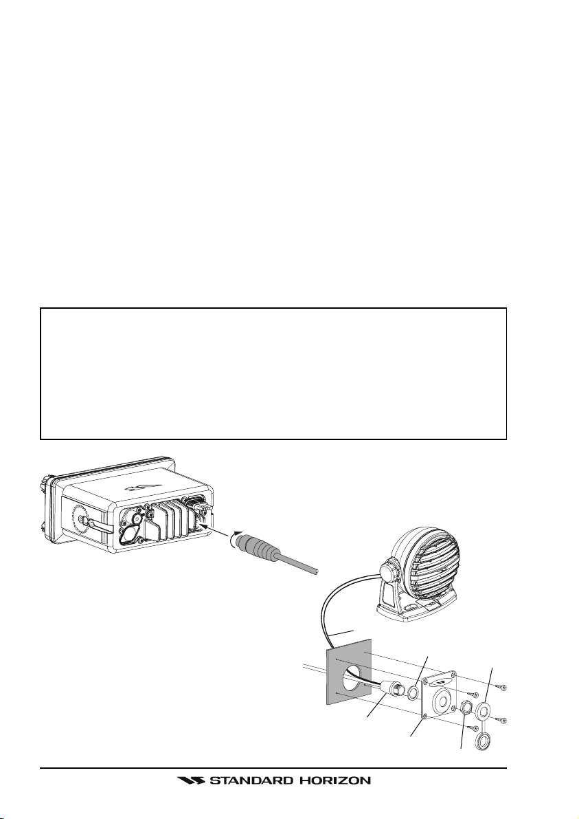
1. Connect the Extension Cable to the Remote Mic eight pin connector on
the rear panel, then tighten the Cable Nut (see illustration below).
2. Referring to illustration below, make a 1.2” (30 mm) hole in the wall, then
insert the Extension Cable into this hole. Connect the Gasket and Mount
Base to the Extension Cable Connector using the Nut.
3. Drill the four Screw holes (approx. 2 mm) on the wall, then install the Mounting Base to the wall using four screws.
4. Put the Rubber Cap on to the Nut. The installation is now complete.
NOTE
The routing cable can be cut and spliced, however care needs to be
taken when reconnecting the wires to ensure water integrity.
Before cutting the cable make sure it is not plugged into the radio. After
cutting you will notice there are the following wires:
Yellow, Green, Brown, Purple, Blue, Green, Red, Shield
The red and shield wires are wrapped in foil. Remove the foil, and
separate the Red and shield wires.
Wall
Routing Cable
External Speaker Connections
Gasket
Mounting Bracket
Cap
Nut
GX2000/GX2100Page 26
Page 27
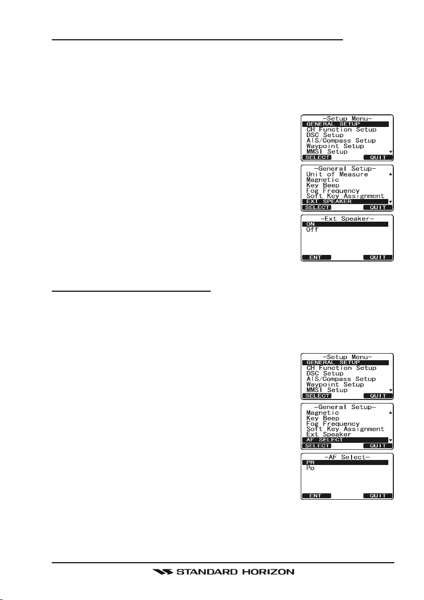
Connecting an External Speaker to the RAM3 Mic Cable
In noisy locations and optional external speaker may be connected to the white
speaker wires on the RAM3 routing cable. The RAM3 can drive the internal
speaker or the external speaker one at a time. When connecting an external
speaker, follow the procedure below to turn off the RAM3 audio and enable
the external speaker wires on the RAM3 routing cable.
1. On the RAM3 mic, press and hold the
[
CALL(MENU)] key until “Setup Menu” appears, then
select “GENERAL SETUP” with the [] / [] key.
2. Press the [ENT] key.
3. Press the [] key to until “EXT SPEAKER” is shown
and press the [SELECT] soft key.
4. Press the [] or [] key to select “OFF” (External
speaker off) or “ON” (External speaker on).
5. Press the [ENT] soft key to save the selection.
6. Press the [16/9] key to exit this mode.
External Speaker AF Selection
The “AF Select” menu allows you to set the audio output level of the RAM3
external speaker wires (on routing cable) to a fixed level regardless of the
volume level setting of the RAM3 which is useful when using the optional MLS-
310 amplified speaker with on/off volume control.
1. On the RAM3 mic, press and hold the
[
CALL(MENU)] key until “Setup Menu” appears, then
select “GENERAL SETUP” with the [] / [] key.
2. Press the [ENT] key.
3. Press the [] key to until “AF SELECT” is shown and
press the [SELECT] soft key.
4. Press the [] or [] key to select “PR” (External
Speaker Level is “Fixed”) or “PO” (External Speaker
Level is “Adjustable”).
“Fixed” use when MLS-310 is connected.
“Adjustable” use when MLS-300 or other speaker
without volume control is connected.
5. Press the [ENT] key to save the selection.
6. Press the [16/9] key to exit this mode.
Page 27GX2000/GX2100
Page 28
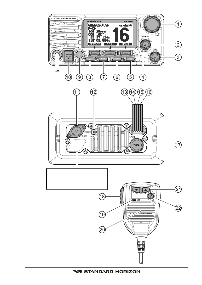
9 CONTROLS AND INDICATORS
NOTE
This section defines each control of the transceiver. See illustration at
the next page for location of controls. For detailed operating instructions
refer to chapter 10 of this manual.
9.1 CONTROLS AND CONNECTIONS
CHANNEL Knob
Rotary knob is used to select channels and to choose menu items (such
as the DSC menu, Radio Setup and DSC Setup menu). The [UP()] /
[
DOWN()] keys on the microphone can also be used to select channels
and menu items.
SECONDARY USE
Press this knob to enter a selection in the “SETUP MENU” or “DSC
MENU”.
While holding down the [SCAN] soft key and turning this knob, you can
confirm memory channels that have been programmed for scanning.
When in the PA or Fog mode, turning this knob changes the output vol-
ume of the connected horn speaker.
PWR/VOL Knob (Power Switch / Volume Control
Turns the transceiver on and off as well as adjusts the speaker volume.
To turn the transceiver on, press and hold this knob until the radio turns on.
When the power is turned on, the transceiver is set to the last selected
channel. Clockwise rotation of this knob increases the internal and speaker
microphone volume.
To turn the transceiver off, press and hold this knob until the radio turns off.
SECONDARY USE
When in PA or Fog mode, controls the listen back volume (GX2100 only).
SQL Knob (Squelch Control
Adjusting this control clockwise, sets the point at which random noise on
the channel does not activate the audio circuits but a received signal does.
This point is called the squelch threshold. Further adjustment of the squelch
control will degrade reception of wanted transmissions.
)
)
GX2000/GX2100Page 28
Page 29
Never remove this rubber cap.
When this rubber cap is removed, the water resistance
performance is lost.
Page 29GX2000/GX2100
Page 30

Soft Keys
The 3 soft keys functions can be customized by the Setup Menu mode
section “12.12 SOFT KEYS”. When one of the soft keys is pressed briefly,
the functions will appear above each key on the display.
[
AIS] Key
Press the [AIS] key to display the AIS (Automatic Identification System)
targets information on the display. Refer to section “15.7 AIS OPERATION”
for details.
Note: For this key to operate on the GX2000 an optional AIS receiver or
transponder and GPS must be connected to show AIS targets on the radios display. On the GX2100 a GPS must be connected to the radio to
show AIS targets on the radios display.
[
CLR(WX)] Key
Press the [CLR(WX)] key briefly to cancel a selection the “Setup Menu”
and “DSC Menu”.
Press and hold the [CLR(WX)] key to recall the previously selected NOAA
weather channel from any channel. Press and hold the [CLR(WX)] key
again reverts to the previous selected working channel.
[
CALL(MENU)] Key
Press the [CALL(MENU)] key to access the “DSC MENU”.
SECONDARY USE
Press and hold the [CALL(MENU)] key to access the “SETUP MENU”.
[
H/L] Key
Press the [H/L] key to toggle between 25 W (High) and 1 W (Low) power.
When the TX output power is set to “Low” while the transceiver is on channel 13 or 67, the output power will temporarily switch from “Low” to “High”
power until the PTT is released. The [H/L] key does not function on transmit inhibited and low power only channels.
SECONDARY USE
When the Normal (Radio display) is selected, push and hold this key to
show or hide SOG and COG on the display.
[
16/9] Key
Press the [16/9] key briefly to recall channel 16 from any channel location.
Press and hold the [CLR(WX)] key to recall channel 9. Pressing the [16/9
key again reverts to the previous selected working channel.
GX2000/GX2100Page 30
]
Page 31

[
DISTRESS] Key
Used to send a DSC Distress Call. To send the distress call refer to section
“11.3.1 Transmitting a DSC Distress Call.”
ANT Jack (Antenna Jack
Connects an antenna to the transceiver. Use a marine VHF antenna with
an impedance of 50 ohms.
Note: On the GX2100 the antenna connection is used to receive marine
and AIS transmissions.
GND Terminal (Ground Terminal
Connects the GX2000/GX2100 to a good ground, for safe and optimum
performance.
Use the screw supplied with the GX2100 and GX2000 only.
Accessory Connection Cable (Green, Blue, Gray, & Brown
Connects the GX2000/GX2100 to a GPS receiver and AIS receiver
(GX2000). Refer to section “8.4 ACCESSORY CABLE”.
PA Speaker Connection Cable (Red & Shield
Connects the GX2000/GX2100 to a optional PA speaker. Refer to section
“3 OPTIONS” for a list of optional STANDARD HORIZON Speakers.
External Speaker Connection Cable (White & Shield
an external speaker. See section “3 OPTIONS” for a list of optional STANDARD HORIZON Speakers.
DC Input Cable
Connects the radio to a DC power supply capable of delivering 11 to 16V
DC.
)
)
)
)
)
RAM3 Connector (Remote Station Microphone Connector
Connects the GX2000/GX2100 to the CMP30 (RAM3) Remote Station
Microphone. Refer to section “17 CMP30 (RAM3) REMOTE MIC OPERA-
TION” for details
PTT Switch (Push-To-Talk Switch
When in radio mode and the PTT button pressed, the transmitter is enabled for voice communications to another vessel. When PA mode is selected, pressing the PTT button allows your voice to be amplified and supplied to a connected PA horn. When a optional RAM3 mic is connected
and intercom mode is selected, pressing the PTT button enables voice
communications from the GX2000 / GX2100 to the RAM3 second station
mic.
)
)
Page 31GX2000/GX2100
Page 32

Microphone
The microphone has ClearVoice Noise Reduction Technology which reduces the amount of background (wind, engine) noise transmitted.
Note: Position your mouth about 1/2” away from the microphone hole and
speak in a normal voice.
Microphone Speaker
Audio heard through internal radio speaker is heard through speaker inside the microphone.
[UP()]
The [UP()] and [DOWN()] on the microphone function the same as the
CH knob on the front panel of the transceiver.
[
16/9] Key
Pressing the [16/9] key immediately recalls channel 16 from any location.
Press and hold the [16/9] key to recall channel 9. Pressing the [16/9] key
again will revert the radio to the previous selected channel.
/ [DOWN()] Keys
GX2000/GX2100Page 32
Page 33

10 BASIC OPERATION
10.1 RECEPTION
1. After the transceiver has been installed, ensure that the power supply and
antenna are properly connected.
2. Press and hold the PWR/VOL knob until the radio turns on.
3. Rotate the SQL knob fully counterclockwise. This state is known as “squelch
off”.
4. Turn up the PWR/VOL knob until noise or audio from the speaker is at a
comfortable level.
5. Rotate the SQL knob clockwise until the random noise disappears. This
state is known as the “squelch threshold.”
6. Rotate the CHANNEL knob to select the desired channel. Refer to the
channel chart on page 121 for available channels.
7. When a message is received, adjust the volume to the desired listening
level. The “ ” indicator on the display indicates communications is
being received.
10.2 TRANSMISSION
1. Perform steps 1 through 6 of RECEPTION.
2. Before transmitting, monitor the channel to ensure it is clear.
THIS IS AN FCC REQUIREMENT!
3. Press the PTT (push-to-talk) switch. The “ ” indicator on the LCD is
displayed.
4. Speak slowly and clearly into the microphone.
5. When the transmission is finished, release the PTT switch.
NOTE
This is a noise-canceling microphone. Position the Oval Slot label “MIC”
within 1/2 inch (1.3 cm) from the mouth for optimum performance.
10.3 TRANSMIT TIME - OUT TIMER (TOT
When the PTT switch on the microphone is held down, transmit time is limited to
5 minutes. This limits unintentional transmissions due to a stuck microphone.
About 10 seconds before automatic transmitter shutdown, a warning beep will be
heard from the speaker(s). The transceiver will automatically go to receive mode,
even if the PTT switch is continually held down. Before transmitting again, the
PTT switch must first be released and then pressed again.
)
Page 33GX2000/GX2100
Page 34

10.4 SIMPLEX/DUPLEX CHANNEL USE
Refer to the VHF MARINE CHANNEL CHART (page 121) for instructions on
use of simplex and duplex channels.
NOTE
All channels are factory-programmed in accordance with FCC (USA),
Industry Canada (Canada), and International regulations. Mode of operation cannot be altered from simplex to duplex or vice-versa.
10.5 DISPLAY TYPE
The GX2000/GX2100 display can be setup to show displays other than the
default “NORMAL” VHF display by using the procedure below:
1. Press and hold down the [CALL(MENU)] key until
“Setup Menu” appears, then select “GENERAL SETUP”
with the CHANNEL knob.
2. Press the [SELECT] soft key, then rotate the CHAN-
NEL knob to select “DISPLAY”.
3. Press the [SELECT] soft key.
4. Rotate the CHANNEL knob to select desired screen
“NORMAL”, “AIS”, “COMPASS”, or “WAYPOINT”.
5. Press the [SELECT] soft key to store the selected
setting.
6. Press the [QUIT] soft key several times to return to
radio operation.
“NORMAL” DISPLAY “COMPASS” DISPLAY“AIS” DISPLAY “WAYPOINT” DISPLAY
NOTE
To show Position information, show AIS targets and use the Compass
display:
GX2100 - external GPS must be connected.
GX2000 - external AIS receiver or transponder and a external GPS must
be connected.
GX2000/GX2100Page 34
Page 35

10.6 USA, CANADA, AND INTERNATIONAL MODE
To change the channel group from USA to Canada or International:
1. Press and hold down the [CALL(MENU)] key
until “Setup Menu” appears.
2. Rotate the CHANNEL knob to select “CH
FUNCTION SETUP”.
2. Press the [SELECT] soft key, then rotate the
CHANNEL knob to select “CH GROUP”.
3. Press the [SELECT] soft key.
4. Rotate the CHANNEL knob to select desired
channel group “USA”, “INTL”, or “CANADA”.
5. Press the [ENT] soft key to store the selected setting.
6. Press the [QUIT] soft key several times to return to radio operation.
10.7 NOAA WEATHER CHANNELS
1. To receive a NOAA weather channel, press and hold the [CLR(WX)] key
for 2 seconds from any channel. The transceiver will go to the last selected
weather channel.
2. Rotate the CHANNEL knob to select a different NOAA weather channel.
3. To exit from the NOAA weather channels, press the [CLR(WX)] key. The
transceiver returns to the channel it was on prior to a weather channel.
10.7.1 NOAA Weather Alert
In the event of extreme weather disturbances, such as storms and hurricanes,
the NOAA (National Oceanic and Atmospheric Administration) sends a weather
alert accompanied by a 1050 Hz tone and subsequent weather report on one
of the NOAA weather channels. When the Weather Alert feature is enabled
(see section “13.6 WEATHER ALERT”), the transceiver is capable of receiv-
ing this alert if the following is performed:
1. Program NOAA weather channels into the transceiver’s memory for scanning. Follow the same procedure as for regular channels under section
“10.9.3 Memory Scanning (M-SCAN).”
2. Press the [SCAN] soft key once to start memory scanning.
3. The programmed NOAA weather channels will be scanned along with the
regular-programmed channels. However, scanning will not stop on a normal weather broadcast unless a NOAA alert is received.
4. When an alert is received on a NOAA weather channel, scanning will stop and
the transceiver will emit a loud beep to alert the user of a NOAA broadcast.
5. Press the [CLR(WX)] key to stop the alert and receive the weather report.
Page 35GX2000/GX2100
Page 36

NOTE
If the [CLR(WX)] key is not pressed the alert will sound for 5 minutes
and then the weather report will be received.
NOTE
While listening to a weather channel, the radio can decode a weather
alert and sound an alarm.
10.7.2 NOAA Weather Alert Testing
NOAA tests the alert system ever Wednesday between 11AM and 1PM. To test
the GX2000/GX2100’s NOAA Weather feature, on Wednesday between 11AM
and 1PM, setup as in section “10.7.1 NOAA Weather Alert” and confirm the
alert is heard.
10.8 DUAL WATCH (TO CHANNEL 16
Dual watch is used to scan two channels for communications. One channel is
a normal VHF channel and the other is the priority, channel 16. When a signal
is received on the normal channel the radio briefly switches between the normal channel and Channel 16 to look for a transmission. If the radio receives
communications on channel 16 the radio stops and listens to Channel 16 until
communication ends and then starts Dual watch scan again.
1. Adjust the SQL knob until the background noise disappears.
2. Select the channel you wish to dual watch to the priority channel 16.
3. Press the one of the Soft keys, then press the [DW] soft key.
The display will scan between CH16 and the channel that was selected in step 2.
If a transmission is received on the channel selected
in step 2, the GX2000/GX2100 will dual watch to
CH16.
4. To stop Dual Watch, press the one of the soft keys, then press the [DW
key soft again.
NOTE
The priority channel may be changed from Ch16 to another channel.
Refer to section “13.5 PRIORITY CHANNEL”.
)
]
GX2000/GX2100Page 36
Page 37

10.9 SCANNING
Allows the user to select the scan type from Memory scan or Priority scan.
“Memory scan” scans the channels that were programmed into memory. “Priority scan” scans the channels programmed in memory with the priority channel.
10.9.1 Selecting the Scan Type
1. Press and hold down [CALL(MENU)] key until
“Setup Menu” appears.
2. Rotate the CHANNEL knob to select “CH
FUNCTION SETUP”.
3. Press the [SELECT] soft key, then select
“SCAN TYPE” with the CHANNEL knob.
4. Press the [SELECT] soft key.
5. Rotate the CHANNEL knob to select “PRIOR-
ITY SCAN” or “MEMORY SCAN”.
6. Press the [SELECT] soft key to store the selected
setting.
7. Press the [QUIT] soft key several times to return to radio operation.
10.9.2 Programming Scan Memory
1. Press and hold down the [CALL(MENU)] key until
“Setup Menu” appears.
2. Rotate the CHANNEL knob to select “CH FUNCTION
SETUP”.
3. Press the [SELECT] soft key, then rotate the CHAN-
NEL knob to select “SCAN MEMORY”.
4. Press the [SELECT] soft key.
5. Rotate the CHANNEL knob to select a desired channel to be scanned, the press the [ADD] soft key.
“MEM” icon appears on the display, which indicates
the channel has been selected to the scan channel.
6. Repeat step 5 for all the desired channels to be
scanned.
7. To DELETE a channel from the list, select the channel then press the [DELETE] soft key. “MEM” icon
disappears from the display.
8. When you have completed your selection, press the [QUIT] soft key several times to return to radio operation.
Page 37GX2000/GX2100
Page 38

10.9.3 Memory Scanning (M-SCAN
)
1. Adjust the SQL knob until background noise disappears.
2. Press the one of the soft key momentarily, then press the [SCAN] soft key.
“M-SCAN” appears on the display. Scanning will proceed from the lowest
to the highest programmed channel number and
Preset channel (described in the next chapter) and
will stop on a channel when a transmission is received.
3. The channel number will blink during reception.
4. To stop scanning, press the [16/9] or [CLR(WX)] key.
10.9.4 Priority Scanning (P-SCAN
)
In the default setting, Channel 16 is set as the priority channel. You may change
the priority channel to the desired channel from Channel 16 by the Radio Setup
Mode, refer to section “13.5 PRIORITY CHANNEL”.
1. Adjust the SQL knob until background noise disappears.
2. Press the one of the soft key momentarily, then press
the [SCAN] key. “P-SCAN” appears on the display.
Scanning will proceed between the memorized
channels and Preset channel (described in next
chapter) and the priority channel. The priority channel will be scanned after each programmed channel.
3. To stop scanning, press the [16/9] or [WX] key.
CH68A
CH68A
CH68A
CH68A
CH88A
CH61A
CH01A
CH22A
MEMORY SCAN (M-SCAN
CH88A
CH01A
Priority Channel
CH09
CH12
CH15
CH18
)
CH09
CH12
CH15
CH61A
CH22A
PRIORITY SCAN (P-SCAN
CH18
)
GX2000/GX2100Page 38
Page 39

10.10 PRESET CHANNELS (0 ~ 9): INSTANT ACCESS
10 Preset Channels can be programmed for instant access. Press the one of
the soft keys, then press the [PRESET] soft key. Pressing the [PRESET] key
activates the user assigned channel bank. If the [PRESET] soft key is pressed
and no channels have been assigned, an alert beep will be emitted from the
speaker.
Before beginning the Instant Access operation, assign the “PRESET” command into the one of the Programmable key, refer to section “12.12 SOFT
KEYS”.
10.10.1 Programming
1. Rotate the CHANNEL knob to select the channel to be programmed.
2. Press the one of the soft keys momentarily to indicate these function on the display, then press and
hold the [PRESET] soft key until the preset channel
number “PRESET0” is displayed.
3. Release the [PRESET] soft key. The preset channel number “PRESET0”
will disappear from the display after five seconds after the [PRESET] soft
key is released.
4. Repeat steps 2 and 3 to program the desired channels into Preset Channels “1” ~ “9”.
5. To delete a preset channel saved into memory:
a. Press one of the soft keys, then press the [PRESET] soft key (repeat-
edly if necessary) until the preset channel appears on the display that
you want to delete.
b. Press and hold the [PRESET] soft key until the radio beeps.
10.10.2 Operation
Pressing the [PRESET] soft key will toggle between
Preset Channels “0” through “9” and the last selected
“regular” channel. The Preset Channel number will disappear after five seconds.
Page 39GX2000/GX2100
Page 40

10.11 PA/FOG OPERATION
The GX2000/GX2100 has a 30W Hailer built-in and can be used with any 4
Ohm PA Horns. Standard Horizon offers a small and a large PA horn called the
220SW and 240SW. When in Hail mode the PA speaker Listen’s Back (acts as
a microphone and sends sound to the front panel speaker and the speaker
mic: GX2100 only) through the PA horn speaker which provides two-way communications through the PA horn speaker.
NOTE
When in PA or FOG mode, the GX2000/GX2100 will receive communications on the last selected VHF channel before entering into the PA or
FOG mode and receive DSC calls.
PA HAIL mode:
PA HAIL mode allows the transceiver to be used as a power hailer when an
optional STANDARD HORIZON 220SW or 240SW HAIL/PA speaker is installed. The Hail mode has a listen-back feature (GX2100 only) which provides two way communication through the HAIL/PA speaker.
FOG HORN mode:
Automatic signaling is transmitted through the HAIL/PA speaker. When the
Fog horn, Bells or Whistle signal is not being outputted the GX2100 listens
back through the connected PA Horn speaker (GX2000 does not have
listen back).
10.11.1 Operating the PA HAIL mode
1. Press one of the Soft keys momentarily, then press
the [PA/FOG] soft key.
Note: The [NEXT] soft key may have to be pressed
to see the [PA/FOG] soft key if the soft keys have
not be customized.
2. Rotate the CHANNEL knob to select “PA”, then press
the [SELECT] soft key.
3. Press the PTT switch to speak through the HAIL/PA
speaker.
Rotate the CHANNEL knob to control the AF output level. The AF output
level can be set from 0 to 30 watts.
4. To listen back (GX2100 only), rotate the PWR/VOL knob.
5. To exit the PA HAIL mode, press the [CLR(WX)] key.
GX2000/GX2100Page 40
Page 41

10.11.2 Operating the FOG HORN mode
The user can select from “Underway”, “Stop”, “Sail”, “Tow”, “Aground”, “Anchor”, “Horn”, and “Siren”.
1. Press the one of the soft keys momentarily, then
press the [PA/FOG] soft key.
Note: The [NEXT] soft key may have to be pressed
to see the [PA/FOG] soft key if the soft keys have
not be customized.
2. Rotate the CHANNEL knob to select “FOG”, then
press the [SELECT] soft key.
3. Rotate the CHANNEL knob to select one of the eight
functions described above.
4. Press the [ENT] soft key.
5. On the “Horn” and “Siren” modes, press the PTT
switch to activate the tone through the HAIL/PA
speaker.
Rotate the CHANNEL knob to control the AF output level. The AF output
level can be set from 0 to 30 watts.
6. To listen back (GX2100 only), rotate the PWR/VOL knob.
7. To exit the FOG HORN mode, press the [CLR(WX)] key.
Page 41GX2000/GX2100
Page 42

10.11.3 Fog Signal Timing Chart
TYPE PATTERN USAGE
UNDERWAY
STOP
SAIL
TOW
One 5-second blasts every 120 seconds.
Listen Back
120s
Two 5-second blasts (separated by 2
seconds) every 120 seconds.
5s 5s
Listen Back
2s 2s
120s
One 5-second blasts followed by two 1second blasts (separated by 2 seconds)
every 120 seconds.
1s 1s1s 1s
2s 2s2s 2s
Listen Back
120s
One 5-second blasts followed by three 1second blasts (separated by 2 seconds)
every 120 seconds.
1s 1s1s 1s1s 1s
Motor vessel underway and
making way.
Motor vessel underway but
stopped (not making way).
Sailing vessel underway, fishing vessel (underway or anchored), vessel not under
command, a vessel restricted
in her ability to maneuver (underway or at anchor), or a vessel towing or pushing another
ahead.
Vessel under tow (manned).
Listen Back
120s
Listen Back
60s
AGROUND
2s 2s2s 2s2s 2s
One 11-second rings every 60 seconds.
ANCHOR One 5-second rings every 60 seconds.
Listen Back
60s
Vessel is aground.
Vessel is at anchor.
GX2000/GX2100Page 42
Page 43

10.12 INTERCOM OPERATION
To access the following Intercom functions one of the soft keys must be setup
as IC. Refer to section “12.12 SOFT KEYS”.
In addition an optional RAM3 must be connected to perform intercom functions between the radio and the RAM3.
10.12.1 Communication
1. Press the one of the soft keys momentarily, then
press the [IC] soft key to enable the intercom mode.
Note: Depending on the programming of the [IC
soft key, the [NEXT] soft key may have to be pressed
to see the [IC] soft key.
2. When the intercom mode is enabled, “Intercom” is displayed on the radio
and CMP30 (RAM3) Remote Station Microphone.
3. Press the PTT switch on the
GX2000/GX2100 CMP30
radio. “Talk” will be shown on
the display.
Note: A warning beep will be
heard when the Radios PTT
and CMP30 (RAM3) PTT are
pushed at the same time.
(
GX2000/GX2100’s PTT switch is pressed
GX2000/GX2100 CMP30
4. Speak slowly and clearly into
the microphone, hold the microphone about 1/2 inch away
(
from your mouth.
CMP30’s PTT switch is pressed
5. When finished, release the PTT switch.
6. Press the [CLR(WX)] key to exit intercom mode and revert to radio mode.
]
)
)
10.12.2 Calling
Press and holding the [IC] soft key when in intercom mode on either the radio
or CMP30 (RAM3) mic will produce a calling beep to the other station.
Page 43GX2000/GX2100
Page 44

10.13 VOICE SCRAMBLER
If privacy of communications is desired, a CVS2500 4 code voice scrambler
(VS) can be installed in the transceiver. Contact your Dealer to have a CVS2500
installed. Refer to the section “13.9 SCRAMBLER SETUP” to program the
voice scrambler.
1. Select a channel that was programmed for scrambler mode (“Vs” and scrambler number will appear
on the display).
2. Monitor the channel before transmitting.
3. Transmit the voice message. The signal sent will be scrambled.
GX2000/GX2100Page 44
Page 45

11 DIGITAL SELECTIVE CALLING
11.1 GENERAL
WARNING
This radio is designed to generate a digital maritime distress and safety
call to facilitate search and rescue. To be effective as a safety device,
this equipment must be used only within communication range of a shorebased VHF marine channel 70 distress and safety watch system. The
range of signal may vary but under normal conditions should be approximately 20 nautical miles.
NOTE
A DSC Warning sticker is included with the
GX2000/GX2100. To comply with FCC
regulations this sticker must be mounted
in a location that can be easily viewed from
the location of the GX2000/GX2100.
Digital Selective Calling is a semi-automated method of establishing a radio
call, it has been designated by the International Maritime Organization (IMO)
as an international standard for establishing VHF, MF and HF radio calls. It has
also been designated as part of the Global Maritime Distress and Safety System (GMDSS).
WAR NING
STICKER
Digital Selective Calling allows mariners to instantly send a distress call with GPS
position (when connected to the transceiver) to the US Coast Guard and other vessels within range of the transmission. DSC will also allow mariners to initiate or receive Distress, Urgency, Safety, Routine, Position Request, Position Report, Automatic Position Polling and Group calls to or from another vessel equipped with a
DSC transceiver.
11.2 MARITIME MOBILE SERVICE IDENTITY (MMSI
)
11.2.1 What is an MMSI?
An MMSI is a nine digit number used on Marine Transceivers capable of using
Digital Selective Calling (DSC). This number is used like a telephone number to
selectively call other vessels.
THIS NUMBER MUST BE PROGRAMMED INTO THE RADIO TO OPERATE
DSC FUNCTIONS.
Page 45GX2000/GX2100
Page 46

How can I obtain an MMSI assignment?
In the USA, visit the following websites to register:
http://www.boatus.com/mmsi/ or
http://seatow.com/boating_safety/mmsi.asp
In the Canada, visit
http://www.ic.gc.ca/epic/site/smt-gst.nsf/en/sf01032e.html or
http://www.usps.org/php/mmsi/rules.php
11.2.2 Programming the MMSI
WARNING
A user MMSI can be inputted only once. Therefore please be careful
not to input the incorrect MMSI number. If you need to change the
MMSI number after it has been entered, the radio will have to be returned
to Factory Service. Refer to the section “18.2 FACTORY SERVICE.”
1. Press and hold down the [CALL(MENU)] key
until the “Setup Menu” appears.
2. Rotate the CHANNEL knob to select “MMSI
SETUP”.
3. Press the [SELECT] soft key. (To cancel, press the
[
ENT] soft key.)
4. Rotate the CHANNEL knob to select the first
number of your MMSI, then press the [ENT
soft key to step to the next number.
5. Repeat step 4 to set your MMSI number (nine
digits).
6. If a mistake was made entering in the MMSI
number, press the [BACK] soft key until the
wrong number is selected, then rotate the
CHANNEL knob to correct the entry and press the
[
ENT] soft key.
7. When finished programming the MMSI number, press
and hold the [ENT] soft key. The radio will ask you to
input the MMSI number again. Use steps 4 - 6 above.
8. After the second number has been input, press and hold the CHANNEL
knob to store the MMSI.
9. Press the [OK] soft key to return to radio operation.
]
NOTE
To view your MMSI after programming to ensure it is correct, perform
steps 1~3. Look that the MMSI number shown on the display is correct.
GX2000/GX2100Page 46
Page 47

11.3 DSC DISTRESS CALL
The GX2000/GX2100 is capable of transmitting and receiving DSC Distress
messages to all DSC radios. The GX2000/GX2100 may be connected to a
GPS to also transmit the Latitude, Longitude of the vessel.
11.3.1 Transmitting a DSC Distress Call
NOTE
To be able to transmit a DSC distress call an MMSI number must be
programmed, refer to section “11.2.2 Programming the MMSI.” In order for your ships location to be transmitted a GPS must be connected
to the GX2000/GX2100, refer to section “8.4 ACCESSORY CABLE.”
1. Lift the red spring loaded DISTRESS cover and
press the [DISTRESS] key. The “DISTRESS ALERT”
menu will appear on the display.
2. Press and hold the [DISTRESS] key. The radios display will count down (3-2-1) and then transmit the
Distress call. The backlight of the display and keypad flashes while the radios display is counting
down.
3. When the distress signal is sent, the transceiver
watches for a transmission between CH16 and CH70
until an acknowledgment signal is received.
4. If an acknowledgment is received, select channel
16 and advise your distress situation.
5. If no acknowledgment is received, the distress call
is repeated in 4 minute intervals until a DSC acknowledgment is received.
6. When a DSC Distress acknowledgment is received,
a distress alarm sounds and channel 16 is automatically selected. The display shows the MMSI of
the ship responding to your distress.
RECEIVED ACK: acknowledgment signal is received.
RECEIVED RLY: relay signal is received from another vessel or coast station.
7. Press the PTT button and state your name, vessel name, number of persons on board and the distress situation, then say over. wait for a reply
from the acknowledging ship.
8. To turn off the Distress alarm until the radio retransmits the distress call,
press the [16/9] key.
Page 47GX2000/GX2100
Page 48

Transmitting a DSC Distress Alert with Nature of Distress
The GX2000/GX2100 is capable of transmitting a DSC Distress Alert with the
following “Nature of Distress” categories:
Undesignated, Fire, Flooding, Collision, Grounding, Capsizing, Sinking,
Adrift, Abandoning, Piracy, MOB
1. Lift the red spring loaded DISTRESS cover and
press the [DISTRESS] key. The “DISTRESS ALERT”
menu will appear on the display.
2. Press the [NATURE] soft key, then rotate the CHAN-
NEL knob to select the desired nature of distress
category.
3. Press and hold the [DISTRESS] key. The radios display will count down (3-2-1) and then transmit the
Distress call. The backlight of the display and keypad flashes while the radios display is counting down.
4. When the distress signal is sent, the transceiver
watches for a transmission between CH16 and CH70
until an acknowledgment signal is received.
5. If no acknowledgment is received, the DSC distress
call is repeated in 4 minute intervals until an acknowledgment is received.
6. When a DSC Distress acknowledgment is received,
a distress alarm sounds and channel 16 is automatically selected. The display shows the MMSI of
the ship responding to your distress.
RECEIVED ACK: acknowledgment signal is re-
ceived.
RECEIVED RLY ACK: relay acknowledgment signal
is received from another vessel or coast station.
7. Press the PTT button and state your name, vessel name, number of persons on board and the distress situation, then say over. wait for a reply
from the acknowledging ship.
8. To turn off the Distress alarm until the radio retransmits the distress call,
press the [16/9] key.
Transmitting a DSC Distress Alert with Manual Position of Input
When the GX2000/GX2100 is not connected to a GPS receiver, you may input
the latitude/longitude of your vessel manually and may send DSC Distress Alert.
1. Lift the red spring loaded DISTRESS cover and press the [DISTRESS]
key. The “DISTRESS ALERT” menu will appear on the display.
GX2000/GX2100Page 48
Page 49

2. Press the [POS/TM] soft key.
3. Enter the latitude/longitude of your vessel and your
local UTC time in the 24-hour notation by the CHAN-
NEL knob. Rotate the CHANNEL knob to select the
number and press the [ENT] soft key to move the
cursor to the next character. You may backspace
the cursor by pressing the [BACK] soft key, if you
make a mistake.
4. When you have completed your selection, press and
hold in the [ENT] soft key for two seconds to save
the setting.
5. Press and hold the [DISTRESS] key. The radios display will count down (3-2-1) and then transmit the
Distress call. The backlight of the display and keypad flashes while the radios display is countdown.
6. When the distress signal is sent, the transceiver
“shadow-watches” for a transmission between CH16
and CH70 until an acknowledgment signal is received.
7. If no acknowledgment is received, the distress call
is repeated in 4 minute intervals until an acknowledgment is received.
8. When a DSC Distress acknowledgment is received,
a distress alarm sounds and channel 16 is automatically selected. The display shows the MMSI of
the ship responding to your distress.
RECEIVED ACK: acknowledgment signal is re-
ceived.
RECEIVED RLY ACK: relay acknowledgment signal is received from another
vessel or coast station.
9. Press the PTT button and state your name, vessel name, number of persons on board and the distress situation, then say over. wait for a reply
from the acknowledging ship.
10. To turn off the Distress alarm until the radio retransmits the distress call,
press the [16/9] key.
Page 49GX2000/GX2100
Page 50

Pausing a DSC Distress Call
After a DSC Distress call is transmitted, the DSC distress call is repeated
every 4 minutes until the call is canceled by the user or until the radio is turned
on and off again. The GX2000/GX2100 has provision to suspend (Pause) the
retransmitting of the distress call by the procedure below.
1. After the distress call is transmitted, the radio will
show the top display to the right.
Looking at this display you will notice TX in: 02:25,
this is the time when the radio will re-transmit the
DSC distress call.
2. To suspend re-transmitting the DSC call, press the
[
PAUSE] soft key.
3. To resume counting down to transmit the DSC Distress call, press the [RESUME] soft key.
Cancel a DSC Distress Call
If a DSC Distress call was sent by error the GX2000/GX2100 allows you to send
a message to other vessels to cancel the Distress Call that was made.
Press the [CANCEL] soft key,
then press [YES] soft key.
11.3.2 Receiving a DSC Distress Call
1. When a DSC Distress call is received, an emergency
alarm sounds.
2. Press any key to stop the alarm.
3. The display shows the position of the vessel in distress. To show additional information of the vessel
in distress, rotate the CHANNEL knob counter clockwise (refer to the second display).
On the display you will notice 3 soft key selections.
These selections are described below:
ACCEPT: Press this key to accept the DSC distress call and to switch to
Channel 16.
Note: If a key is not pressed for 10 seconds or longer the radio will automatically select Channel 16.
PAUSE: Press this key to temporarily disable automatic switching to channel 16.
QUIT: Press this key to quit the automatic channel 16 switching and revert
GX2000/GX2100Page 50
Page 51

to the last selected working channel.
4. Press the [WPT] soft key to enter the “Waypoint In-
put” menu, then enter the desired waypoint name
(up to 11 characters), described previously (select
the letter/number by rotating the CHANNEL knob
and move the cursor by pressing the [ENT]/[BACK
Receiv ed DISTRESS
Name:VERTEX
ID:1234567 89
Since: 01:03
-D ISTR ESS IN FO-
Nature of:Undesignate
DIST I D:123456789
]
soft key).
6. The ID is the MMSI from the vessel in distress.
7. When you are finished entering the waypoint name,
press and hold the [ENT] soft key to replace the
display to the “WAYPOINT” Screen. The display indicates the distance and direction of the distressed
vessel, and also the compass indicates the distressed vessel by dot ().
8. To return to the radio operation:
1) Press and hold down the [CALL(MENU)] key until “Setup Menu” ap-
pears.
2) Rotate the CHANNEL knob to select “DSC SETUP” menu.
3) Press the [SELECT] soft key, then select “GENERAL SETUP” with the
CHANNEL knob.
4) Press the [SELECT] soft key, then select “NORMAL” with the CHANNEL
knob.
5) Press the [SELECT] soft key to return to radio operation.
QUITWPT
NOTE
You must continue monitoring channel 16 as a coast station may require assistance in the rescue attempt.
Page 51GX2000/GX2100
Page 52

11.4 ALL SHIPS CALL
The All Ships Call function allows contact to be established with DSC equipped
vessels without having their MMSI in the individual calling directory. Also, priority for the call can be designated as Urgency or Safety.
URGENCY Call:This type of call is used when a vessel may not truly be in
distress, but have a potential problem that may lead to a distress situation. This call is the same as saying PAN PAN PAN
on channel 16.
SAFETY Call: Used to transmit boating safety information to other vessels.
This message usually contains information about an overdue
boat, debris in the water, loss of a navigation aid or an important meteorological message. This call is the same as saying
Securite, Securite, Securite.”
11.4.1 Transmitting an All Ships Call
1. Press the [CALL(MENU)] key. The “DSC
Menu” will appear.
2. Rotate the CHANNEL knob to select “All
SHIPS”.
3. Press the [SELECT] soft key. (To cancel,
press the [QUIT] soft key.)
4. Rotate the CHANNEL knob to select the nature of call (“SAFETY” or “URGENCY”), then
press the [SELECT] soft key.
5. Rotate the CHANNEL knob to select the operating
channel you want to communicate on, then press
the [SELECT] soft key. If the channel you want to
use is not listed, press the [MANUAL] soft key, then
rotate the CHANNEL knob to select the operating
channel you want to communicate on, then press
the [SELECT] soft key.
6. Press the [YES] soft key to transmit the selected
type of all ships DSC call.
7. After the All Ships Call is transmitted, the transceiver
will switch to the selected channel.
8. Listen to the channel to make sure it is not busy,
then key the microphone and say PAN PAN PAN or
“Securite, Securite, Securite” depending on the priority of the call.
9. Press the [QUIT] soft key to exit the ALL ship call menu.
GX2000/GX2100Page 52
Page 53

11.4.2 Receiving an All Ships Call
1. When an all ships call is received, an emergency
alarm will sound.
The display shows the MMSI of the vessel transmitting the All Ships Call and the radio will change
to the requested channel after 10 seconds.
2. Press any key to stop the alarm.
3. Monitor the requested channel until the ALL SHIPs
voice communication is completed.
On the display you will notice 3 soft key selections.
These selections are described below:
ACCEPT: Press this key to accept the DSC All Ship
call and to switch to requested channel.
Note: If a key is not pressed for 10 seconds or longer the radio will automatically change to the requested channel.
PAUSE: Press this key to temporarily disable automatic switching to the
requested channel.
Note: In some cases automatically switching to a requested channel might
disrupt import ongoing communications. This feature allows commercial
users to suspend channel switching and stay on the working channel selected before the All Ships call was received.
QUIT: Press this key to quit the automatic channel switching and revert to
the last selected working channel.
4. Press the [CALL(MENU)] key to return to the channel display.
Page 53GX2000/GX2100
Page 54

11.5 INDIVIDUAL CALL
This feature allows the GX2000/GX2100 to contact another vessel with a DSC
VHF radio and automatically switch the receiving radio to a desired communications channel. This feature is similar to calling a vessel on CH16 and requesting to go to another channel (switching to the channel is private between
the two stations). Up to 80 Individual contacts may be programmed.
11.5.1 Setting up the Individual / Position Call Directory
The GX2000/GX2100 has a DSC directory that allows you to store a vessel or
person’s name and the MMSI number associated with vessels you wish to
transmit Individual calls, Auto Polling, Position Request, and Position Report
transmissions.
To transmit an Individual call you must program this directory with information
of the persons you wish to call, similar to a cellular phones telephone directory.
1. Press and hold down the [CALL(MENU)] key
until “Setup Menu” appears.
2. Rotate the CHANNEL knob to select “DSC
SETUP” menu.
3. Press the [SELECT] soft key, then select “INDI-
VIDUAL DIRECTORY” with the CHANNEL knob.
4. Press the [SELECT] soft key.
5. Select “ADD” with the CHANNEL knob, then
press the [SELECT] soft key.
6. Rotate the CHANNEL knob to scroll through
the first letter of the name of the vessel or person
you want to reference in the directory.
7. Press the [ENT] soft key to store the first letter in
the name and step to the next letter to the right.
8. Repeat step 6 and 7 until the name is complete.
The name can consist of up to eleven characters, if
you do not use all eleven characters press the [ENT
soft key to move to the next space. This method
can also be used to enter a blank space in the name.
If a mistake was made entering in the name repeat
pressing the [BACK] soft key until the wrong character is selected, then
rotate the CHANNEL knob to correct the entry.
9. After the eleventh letter or space has been entered, press and hold the
[
ENT] soft key to advance to the MMSI (Maritime Mobile Service Identity
Number) number entry.
10. Rotate the CHANNEL knob to scroll through numbers, 0-9. To enter the
]
GX2000/GX2100Page 54
Page 55

desired number and move one space to the right by
pressing the [ENT] soft key. Repeat this procedure
until all nine space of the MMSI number are entered.
11. If a mistake was made entering in the MMSI number
repeat pressing the [BACK] soft key until the wrong number is selected,
then rotate the CHANNEL knob to correct the entry.
12. To store the data entered, press and hold the [ENT] soft key.
13. To enter another individual address, repeat steps 5 through 12.
14. Press the [QUIT] soft key several times to return to radio operation.
11.5.2 Setting up Individual Reply
This menu item sets up the radio to automatically (default setting) or manually
respond to a DSC Individual call requesting you to switch to a working channel
for voice communications. When Manual is selected the MMSI of the calling
vessel is shown allowing you to see who is calling. This function is similar to
caller id on a cellular phone.
1. Press and hold down the [CALL(MENU)] key
until “Setup Menu” appears.
2. Rotate the CHANNEL knob to select “DSC
SETUP” menu.
3. Press the [SELECT] soft key, then select “IN-
DIVIDUAL REPLY” with the CHANNEL knob.
4. Press the [SELECT] soft key.
5. Rotate the CHANNEL knob to select “AUTO-
MATIC” or “MANUAL”.
6. Press the [SELECT] soft key to store the selected
setting.
7. Press the [QUIT] soft key several times to return to radio operation.
11.5.3 Enabling the Individual Acknowledgment
The radio can be setup to transmit a reply automatically (default) or set so the
radio will not reply to an individual call.
1. Press and hold down the [CALL(MENU)] key
until “Setup Menu” appears.
2. Rotate the CHANNEL knob to select “DSC
SETUP” menu.
3. Press the [SELECT] soft key, then select “IN-
DIVIDUAL ACK” with the CHANNEL knob.
4. Press the [SELECT] soft key.
5. Rotate the CHANNEL knob to select “ABLE
Page 55GX2000/GX2100
Page 56

TO COMPLY” or “UNABLE”.
6. Press the [ENT] soft key to store the selected setting, then press the [QUIT] soft key several times to
return to radio operation.
11.5.4 Setting up Individual/Group Call Ringer
When a Individual Call or Group Call is received the radio will produce a ringing sound for 2 minutes. This selection allows the Individual Call ringer time to
be changed.
1. Press and hold down the [CALL(MENU)] key
until “Setup Menu” appears.
2. Rotate the CHANNEL knob to select “DSC
SETUP” menu.
3. Press the [SELECT] soft key, then select “IN-
DIVIDUAL RING” with the CHANNEL knob.
4. Press the [SELECT] soft key.
5. Rotate the CHANNEL knob to select ringing
time of a Individual Call.
6. Press the [ENT] soft key to store the selected setting, then press the [QUIT] soft key several times to
return to radio operation.
The GX2000/GX2100 has the capability to turn off the Individual and Group
call ringer.
1. Press and hold down the [CALL(MENU)] key
until “Setup Menu” appears.
2. Rotate the CHANNEL knob to select “DSC
SETUP” menu.
3. Press the [SELECT] soft key, then select “DSC
BEEP” with the CHANNEL knob.
4. Press the [SELECT] soft key.
5. Rotate the CHANNEL knob to select “Indi-
vidual” if you wish to disable the Individual call
ringer, or “Group” if you wish to disable the Group
call ringer, then press the [SELECT] soft key.
6. Rotate the CHANNEL knob to select “Off”.
7. Press the [ENT] soft key to store the selected setting.
8. Press the [QUIT] soft key several times to return to radio operation.
To re-enable the ringer tone, repeat the above procedure, rotating the CHAN-
NEL knob to select “On” in step “6” above.
GX2000/GX2100Page 56
Page 57

11.5.5 Transmitting an Individual Call
This feature allows the user to contact another vessel with a DSC radio. This
feature is similar to calling a vessel on CH16 and requesting to go to another
channel.
Pre-Programmed Calling
1. Press the [CALL(MENU)] key. The “DSC
Menu” will appear.
2. Rotate the CHANNEL knob to select “INDIVIDUAL”. (To cancel, press the [QUIT] soft
key.)
3. Press the [SELECT] soft key. The transceiver
will beep, and the “Last Individual Call” will
appear.
4. Rotate the CHANNEL knob to select the “Individual” you want to contact.
5. Press the [SELECT] soft key, then rotate the CH
knob to select the operating channel you want to
communicate on, then press the [SELECT] soft key.
If the channel is not shown in the list, press the
[
MANUAL] soft key, then rotate the CHANNEL knob
to select the operating channel you want to communicate on, then press the [SELECT] soft key.
6. Press the [YES] soft key to transmit the individual
DSC signal.
7. When an individual call acknowledgment is received,
the established channel is automatically changed
to the channel which is selected on step 5 above
and a ringing tone sounds.
8. Press the [QUIT] soft key to listen to the channel to
make sure it is not busy, then press the microphone’s PTT switch and talk
into the microphone to the other vessel.
Manual Calling
You may enter an MMSI number manually to contact without storing it in the
Individual Directory.
1. Press the [CALL(MENU)] key. The “DSC Menu”
menu will appear.
2. Rotate the CHANNEL knob to select “INDIVIDUAL”.
(To cancel, press the [QUIT] soft key.)
Page 57GX2000/GX2100
Page 58

3. Press the [SELECT] soft key. The transceiver will
beep, and the “Last Individual Call” will appear.
4. Press the [NEW ID] soft key, then select “MANUAL”
with the CHANNEL knob.
5. Press the [SELECT] soft key.
6. Rotate the CHANNEL knob to select the first number of the MMSI which you want to contact, then
press the [SELECT] soft key to step to the next number.
7. Repeat step 6 to set the MMSI number (nine digits).
8. If a mistake was made entering in the MMSI number, repeat pressing the [BACK] key until the wrong
number is selected, then rotate the CHANNEL knob
to correct the entry.
9. When finished entering the MMSI number, press and
hold the [SELECT] soft key.
10. Press the [SELECT] soft key, then rotate the CHAN-
NEL knob to select the operating channel you want
to communicate on, then press the [SELECT] soft
key. If the channel is not shown in the list, press the
[
MANUAL] soft key, then rotate the CHANNEL knob
to select the operating channel you want to communicate on, then press the [SELECT] soft key.
11. Press the [YES] soft key to transmit the individual
DSC signal.
12. When an individual call acknowledgment is received,
the established channel is automatically changed
to the channel which is selected on step 5 above
and a ringing tone sounds.
13. Press the [QUIT] soft key to listen to the channel to
make sure it is not busy, then press the microphone’s
PTT switch and talk into the microphone to the other
vessel.
GX2000/GX2100Page 58
Page 59

11.5.6 Receiving an Individual Call
When a Individual DSC call is received, the radio will automatically respond
(Default setting) to the calling ship, and switch to the requested channel for
voice communications. Refer to section “11.5.2 Setting up Individual Reply” to
change the reply to manual if you want to see who is calling before replying to
the call.
1. When an individual call is received, an individual
call ringing alarm sounds.
The radio automatically switches to the requested
channel. The display shows the MMSI of the vessel
calling.
2. Press any key to stop the alarm.
3. Press the [QUIT] soft key to return to radio operation
4. Press the microphone’s PTT switch and talk into the microphone to the
other vessel.
Page 59GX2000/GX2100
Page 60

11.6 DSC LOG OPERATION
The GX2000/GX2100 logs received distress calls and individual calls. The
DSC Log feature is similar to an answer machine where calls are recorded for
review and a “ ” icon will appear on the radios display. The GX2000/GX2100
can store up to the latest 26 Distress, and up to the latest 64 other calls (Individual, Group, All Ship etc.).
11.6.1 Reviewing and Relaying a Logged DSC Distress Call
The GX2000 / GX2100 radios allows logged DSC distress call to be reviewed
and relayed to a specific MMSI.
1. Press the [CALL(MENU)] key. The “DSC
menu” will appear.
2. Rotate the CHANNEL knob to select “DSC
LOG” menu.
3. Press the [SELECT] soft key, then rotate the CHAN-
NEL knob to select “DISTRESS LOG”.
4. Press the [SELECT] soft key, then rotate the
CHANNEL knob to select the station (name
or MMSI number) you want to review and/or
relay the distress call to other vessels.
Note: When there is an unread received call,
“ ” icon will appear behind the station name
(or MMSI number).
5. Press the [SELECT] soft key, to review details for the selected station.
6. To relay the logged DISTRESS call to a station programmed into the Individual directory,
press the [RELAY] soft key, rotate the CHAN-
NEL knob to the vessel name or MMSI and press
the [SELECT] soft key.
7. Press the [YES] soft key to reply the logged Distress call.
NOTE
Not all DSC radios can receive a DSC distress relay call.
GX2000/GX2100Page 60
Page 61

11.6.2 Reviewing a Logged All Ship or Individual Call
Reviewing a logged All ship or Individual call.
1. Press the [CALL(MENU)] key. The “DSC
Menu” will appear.
2. Rotate the CHANNEL knob to select “DSC
LOG” menu.
3. Press the [SELECT] soft key, then rotate the CHAN-
NEL knob to select “OTHER CALL LOG”.
4. Press the [SELECT] soft key, then rotate the
CHANNEL knob to select the station (name or
MMSI number) you want to review and/or call
back. When there is an unread received call,
“ ” icon will appear behind the station name
(or MMSI number).
5. Press the [SELECT] soft key, to review details for the selected station.
Page 61GX2000/GX2100
Page 62

11.6.3 Deleting a Call from the “DSC LOG” Directory
1. Press the [CALL(MENU)] key. The “DSC
Menu” will appear.
2. Rotate the CHANNEL knob to select “DSC
LOG” menu.
3. Press the [SELECT] soft key, then rotate the CHANNEL knob to select “LOG DELETE” menu.
4. Press the [SELECT] soft key, then rotate the
CHANNEL knob to select the category (“DISTRESS LOG” or “OTHER CALL LOG”) to be de-
leted.
5. Press the CHANNEL knob.
1) If you want to delete all stations at a time, select
the “ALL LOG DELETE” with the CHANNEL knob,
then press the [SELECT] soft key, then press the
[OK]
soft key. Press the [QUIT] soft key several
times to return to radio operation.
2) If you want to delete one of
the logged stations, select
the “VIEW LOG LIST” with
the CHANNEL knob, then
press the [SELECT] soft
key. Rotate the CHANNEL
knob to select the station
(name or MMSI number) to
be deleted, then press the
[
DELETE] soft key. The display will show “Are your
sure?” press the [OK] soft key.
6. Press the [QUIT] soft key several times to return to
radio operation.
“VIEW LOG LIST”“ALL LOG DELETE”
GX2000/GX2100Page 62
Page 63

11.7 GROUP CALL
This feature allows the user to contact a group of specific vessels (example
members of a yacht club) using DSC radios with Group call function to automatically switch to a desired channel for voice communications. This function
is very useful for yacht clubs and vessels traveling together that want to collectively make announcements on a predetermined channel. Up to 32 Group
MMSI may be programmed.
11.7.1 Setup a Group Call
For this function to operate, the same Group MMSI must be programmed into
all the DSC VHF radios within the group of vessels that will be using this feature. To understand Group MMSI programming, first a Ship MMSI has to be
understood.
Ship MMSI: The first three digits called a MID (Mobile Identity Group) of a Ship
MMSI denote the country the ship registered for a MMSI. The last 6 digits are
specific to the Ships ID.
Ship MMSI Example: If your MMSI is “366123456”, “366” is MID which denote
the country and “123456” is your ships MMSI.
Group MMSI:
Group MMSI numbers are not assigned by the FCC or other organizations
licensed to assign ship MMSI numbers.
The first digit of a Group MMSI is always set to “0” by International rules.
All Standard Horizon radios are preset so when programming a Group
MMSI the first digit is set to “0”.
The USCG recommends programming the MID of a ships MMSI into the
Second, Third and Fourth digits of the Group MMSI as it denotes the area
the ship is located in.
The last 5 digits are decided upon by persons in the Group. This is an
important step as all radios in the Group must contain the same Group
MMSI so they can be contacted by each other. There is a chance that
another group of vessels may program in the same Group MMSI. If this
happens, simply change one or more of the last 5 digits of the Group MMSI.
1. Press and hold down the [CALL(MENU)] key until
“Setup Menu” appears.
2. Rotate the CHANNEL knob to select “DSC SETUP”
menu.
3. Press the [SELECT] soft key, then select “GROUP
DIRECTORY” with the CHANNEL knob.
4. Press the [SELECT] soft key, then select “ADD” with
the CHANNEL knob.
Page 63GX2000/GX2100
Page 64

5. Press the [SELECT] soft key.
6. Rotate the CHANNEL knob to scroll through the first
letter of the name of the group you want to reference in the directory.
7. Press the [SELECT] soft key to store the first letter
in the name and step to the next letter to the right.
8. Repeat step 6 and 7 until the name is complete.
The name can consist of up to eleven characters, if
you do not use all eleven characters press the [SE-
LECT] soft key to move to the next space. This
method can also be used to enter a blank space in
the name. If a mistake was made entering in the
name repeat pressing the [BACK] soft key until the
wrong character is selected, then rotate the CHAN-
NEL knob to correct the entry.
9. After the eleventh letter or space has been entered, press and hold the
[
SELECT] soft key to advance to the GROUP MMSI (Maritime Mobile Ser-
vice Identity Number) number entry.
10. Rotate the CHANNEL knob to select the second number of the MMSI (nine
digits: first digit permanently set to “0”) which you
want to contact, then press the [SELECT] soft key
to step to the next number. Repeat this procedure
until all eight space of the MMSI number are entered.
11. If a mistake was made entering in the MMSI number repeat pressing the
[
BACK] soft key until the wrong number is selected, then rotate the CHAN-
NEL knob to correct the entry.
12. To store the data entered, press and hold the [SELECT] soft key.
13. To enter another group address, repeat steps 5 through 12.
14. Press the [QUIT] soft key several times to return to radio operation.
11.7.2 Transmitting a Group Call
Pre-Programmed Calling
1. Press the [CALL(MENU)] key. The “DSC
Menu” will appear.
2. Rotate the CHANNEL knob to select
“GROUP”. (To cancel, press the [QUIT] key.)
3. Press the [SELECT] soft key. The transceiver will
beep, and the “Last Group Call” will appear.
4. Rotate the CHANNEL knob to select the “Group”
you want to contact.
GX2000/GX2100Page 64
Page 65

5. Press the [SELECT] soft key, then rotate the
CHANNEL knob to select the operating channel you want to communicate on, then press
the [SELECT] soft key. If the channel you want
is not shown, press the [MANUAL] soft key, then
rotate the CHANNEL knob to select the operating
channel you want to communicate on, then press
the [SELECT] soft key.
6. Press the [YES] soft key to transmit the Group Call
signal.
7. When the Group Call signal is sent, the display will be as shown in the illustration at the
right.
8. After the Group Call is transmitted, all the radios in
the group will switch to the designated channel.
9. Listen to the channel to make sure it is not busy,
then press the microphone’s PTT switch and call
the other vessel you desire to communicate with.
Manual Calling
This feature allows you to contact a group of vessels by entering in their Group
MMSI manually.
1. Press the [CALL(MENU)] key. The “DSC
Menu” will appear.
2. Rotate the CHANNEL knob to select
“GROUP”. (To cancel, press the [QUIT] soft
key.)
3. Press the [SELECT] soft key. The transceiver
will beep, and the “Last Group Call” will appear.
4. Select “MANUAL” with the CHANNEL knob.
5. Press the [SELECT] soft key.
6. Rotate the CHANNEL knob to select the first
number of the MMSI (nine digits: first digit permanently set to “0”) which you want to contact, then press the [SELECT] soft key to step
to the next number.
7. Repeat step 6 to set the MMSI number.
8. If a mistake was made entering in the MMSI
Page 65GX2000/GX2100
Page 66

number, repeat pressing the [BACK] soft key until the wrong number is
selected, then rotate the CHANNEL knob to correct the entry.
9. When finished entering the MMSI number, press and hold the [SELECT
soft key.
10. Rotate the CHANNEL knob to select the operating channel you want to
communicate on, then press the [SELECT] soft key. If the channel you
want is not shown, press the [MANUAL] soft key, then rotate the CHAN-
NEL knob to select the operating channel you want to communicate on,
then press the [SELECT] soft key.
11. Press the [YES] soft key to transmit the Group
Call signal.
12. After the Group Call is transmitted, all the radios in the group will switch to the designated
channel.
13. Listen to the channel to make sure it is not
busy, then press the PTT button and talk into
the microphone to the group of vessels.
11.7.3 Receiving a Group Call
1. When a group call is received, the GX2000/GX2100 will produce a ringing
alarm sound.
2. The radio will automatically switch to the requested
channel.
3. Press the [QUIT] soft key to stop the alarm.
4. Monitor the channel for the person calling the Group for a message.
5. If you want to respond, monitor the channel to make sure it is clear, then
press the microphone’s PTT switch and talk into the microphone to the
group of vessels.
6. Press the [QUIT] soft key to return to radio operation.
]
NOTE
After a Group call is received, the time the call was made and the ships
MMSI or vessels name will appear on the display.
GX2000/GX2100Page 66
Page 67

11.8 POSITION REQUEST
Advancements in DSC have made it possible to poll the location of another
vessel and show the position of that vessel on the display of the GX2000/
GX2100. Standard Horizon has taken this feature one step further, if any compatible GPS chart plotter is connected to the GX2000/GX2100, the polled position of the vessel is shown on the display of the GPS chart plotter making it
easy to navigate to the location of the polled vessel. This is a great feature for
anyone wanting to know the position of another vessel. For example your buddy
that is catching fish, or finding the location of a person you are cruising with.
NOTE
The other vessel must have an operating GPS receiver connected to its
DSC radio and must not have its radio set not to deny position requests.
(Refer the section “11.5 INDIVIDUAL CALL” to enter information into
the individual directory).
11.8.1 Setting up a Position Reply
The GX2000/GX2100 can be set up to automatically (default setting) or manually send your position when requested by another vessel. This selection is
important if you are concerned about someone polling the position of your
vessel that you may not want to. In the manual mode you will see the MMSI or
persons name shown on the display allowing you to choose to send your position to the requesting vessel.
1. Press and hold down the [CALL(MENU)] key until
“Setup Menu” appears.
2. Rotate the CHANNEL knob to select “DSC SETUP”
menu.
3. Press the [SELECT] soft key, then select “POSITION
REPLY” with the CHANNEL knob.
4. Press the [SELECT] soft key, then select “AUTO-
MATIC” or “MANUAL”. In “AUTOMATIC” mode, after
a DSC POS Request is received, the radio will automatically transmit your vessels position. In
“MANUAL” mode, the display of the GX2000/GX2100
will show who is requesting the position and the YES
soft key on radio has to be pressed to send your
position to the requesting.
5. Press the [ENT] soft key to store the selected setting.
6. Press the [QUIT] soft key several times to return to radio operation.
Page 67GX2000/GX2100
Page 68

11.8.2 Setting up a Position Request Ringer
The GX2000/GX2100 has the capability to turn off the Position Request ringer.
1. Press and hold down the [CALL(MENU)] key
until “Setup Menu” appears.
2. Rotate the CHANNEL knob to select “DSC
SETUP” menu.
3. Press the [SELECT] soft key, then select “DSC
BEEP” with the CHANNEL knob.
4. Press the [SELECT] soft key, then select “POS
Request” with the CHANNEL knob.
5. Press the [ENT] soft key, then select “Off” with
the CHANNEL knob.
6. Press the [ENT] soft key to store the selected setting.
7. Press the [QUIT] soft key several times to return to radio operation.
To re-enable the ringer tone, repeat the above procedure, rotating the CHAN-
NEL knob to select “On” in step “5” above.
11.8.3 Transmitting a Position Request to Another Vessel
Pre-Programmed Request
1. Press the [CALL(MENU)] key. The “DSC
Menu” will appear.
2. Rotate the CHANNEL knob to select “POS REQUEST”.
3. Rotate the CHANNEL knob to select a name
that was stored in the Individual DSC directory, then press the [SELECT] soft key.
4. Press the [YES] soft key to transmit the Position Request DSC call.
5. When the GX2000/GX2100 receives the position
from the polled vessel it is shown on the radio display and also transferred to a GPS
Chart plotter with NMEA DSC and DSE sentences.
6. Press the [QUIT] soft key to return to radio operation.
NOTE
If the GX2000S/GX2100S does not receive a position data from the
polled vessel, the display will show “NO POSITION DATA.”
GX2000/GX2100Page 68
Page 69

Manual Request
This feature allows you to request the position of vessel by manually entering
the MMSI of the ship you want to send your position to.
1. Press the [CALL(MENU)] key. The “DSC Menu” will appear.
2. Rotate the CHANNEL knob to select “POS REQUEST”.
3. Press the [SELECT] soft key to show the “Last
Individual Call”.
4. Rotate the CHANNEL knob to select the
“MANUAL,” then press the [SELECT] soft key.
5. Rotate the CH knob to select the first number
of the MMSI (nine digits) which you want to
contact, then press the [SELECT] soft key to
step to the next number.
6. Repeat step 5 to set the MMSI number.
7. If a mistake was made entering in the MMSI
number, repeat pressing the [BACK] soft key
until the wrong number is selected, then rotate the CHANNEL knob to correct the entry.
8. When finished entering the MMSI number,
press and hold the [SELECT] soft key.
9. Press the [YES] soft key to transmit the position request DSC call.
10. When the GX2000/GX2100 receives the position
from the polled vessel it is shown on the radio display and also transferred to the GPS Chart plotter
with NMEA DSC and DSE sentences.
11. Press the [QUIT] soft key to return to radio operation.
11.8.4 Receiving a Position Request
When a position request call is received from another vessel, a ringing alarm
sounds and POS REQUEST will be shown in the display. Operation and transceiver function differs depending on “Position Reply” in the “DSC Setup” menu
setting discussed below:
Automatically reply:
1. When a position request call is received, a calling
alarm sounds 4 times. Then requested position coordinates are transmitted automatically to the vessel requesting your vessels position.
2. To exit from position request display, press the [QUIT] soft key.
Page 69GX2000/GX2100
Page 70

Manually reply:
1. When a position request call is received from another vessel, the display will be as shown in the illustration at the right.
2. A ringing alarm sounds 4 times. To send your vessels position to the requesting vessel, press the [RE-
PLY] soft key. Or to exit from position request dis-
play, press the [QUIT] soft key.
GX2000/GX2100Page 70
Page 71

11.9 POSITION REPORT
The feature is similar to Position Request, however instead of requesting a
position of another vessel this function allows you to send your position to
another vessel. Your vessel must have an operating GPS receiver connected
for the GX2000/GX2100 to send the position.
NOTE
To transmit a Position Report Call, a GPS must be connected to the
radio and the GX2000 / GX2100 Individual directory must be programmed
with stations you wish to send your position to. To setup this directory
refer to section “11.5.1 Setting up the Individual / Position Call Direc-
tory.”
11.9.1 Setting up a Position Report Ringer
The GX2000/GX2100 has the capability to turn off the Position Report ringer.
1. Press and hold down the [CALL(MENU)] key
until “Setup Menu” appears.
2. Rotate the CHANNEL knob to select “DSC
SETUP” menu.
3. Press the [SELECT] soft key, then select “DSC
BEEP” with the CHANNEL knob.
4. Press the [SELECT] soft key, then select “POS
Report” with the CHANNEL knob.
5. Press the [ENT] soft key, then select “Off” with
the CHANNEL knob.
6. Press the [ENT] soft key to store the selected setting.
7. Press the [QUIT] soft key several times to return to
radio operation.
To re-enable the ringer tone, repeat the above procedure, rotating the CHAN-
NEL knob to select “On” in step “5” above.
11.9.2 Transmitting a DSC Position Report Call
Pre-Programmed Calling
1. Press the [CALL(MENU)] key. The “DSC
Menu” will appear.
2. Rotate the CHANNEL knob to select “POS REPORT”. (To cancel, press the [QUIT] soft key.)
3. Press the [SELECT] soft key.
4. Rotate the CHANNEL knob to select the name in
Page 71GX2000/GX2100
Page 72

the directory, then press the [SELECT] soft
key.
5. Press the [YES] soft key to send your position to the selected vessel.
6. Press the [QUIT] key to return to radio operation.
Manual Calling
This feature allows you to send your position to another vessel by manually
entering the MMSI of the ship you want to send your position to.
1. Press the [CALL(MENU)] key. The “DSC
Menu” will appear.
2. Rotate the CHANNEL knob to select “POS RE-
PORT”. (To cancel, press the [QUIT] soft key.)
3. Press the [SELECT] soft key. The transceiver will
beep, and the “Position Report Call” menu will appear.
4. Rotate the CHANNEL knob to select
“MANUAL”, then press the [SELECT] soft key.
5. Rotate the CHANNEL knob to select the first
number of the MMSI which you want to contact, then press the [SELECT] soft key to step
to the next number.
6. Repeat step 5 to set the MMSI number.
7. If a mistake was made entering in the MMSI
number, repeat pressing the [BACK] soft key
until the wrong number is selected, then rotate the CHANNEL knob to correct the entry.
8. When finished entering the MMSI number,
press and hold the Press the [SELECT] soft
key.
9. Press the [YES] soft key to send your position to the selected vessel.
10. Press the [CLR(WX)] key to return to radio operation.
GX2000/GX2100Page 72
Page 73

11.9.3 Receiving a DSC Position Report Call
When another vessel transmits their vessels location to the GX2000/GX2100
the following will happen:
1. A ringing sound will be produced when the call is received and NMEA
sentences DSC, DSE are outputted so the position
can be shown on a chart plotter or a computer.
2. Press the [CLR(WX)] key to stop ringing.
3. Rotate the CHANNEL knob to see position information of the station.
4. To exit to radio mode, press the [QUIT] soft key.
11.9.4 Navigating to a Position Report
The GX2000/GX2100 has a feature that allows navigation to a received Position Report call by using the Compass display. Navigating to the position of a
Position Report call may be enabled by the procedure below.
1. After the Position Report call has been received: press the [TO WPT] soft key.
2. To start navigating using the compass display,
press and hold the [ENT] soft key until the
Compass Page is shown. The display indicates the
distance and direction of the received vessel, and
also the compass indicates the received vessel by
dot ().
Stop Navigating to a Position Report
To stop navigation and return to the radio mode:
1. Press and hold down the [CALL(MENU)] key until
“Setup Menu” appears.
2. Rotate the CHANNEL knob to select “GENERAL
SETUP” menu.
3. Press the [SELECT] soft key, then select “DISPLAY”
with the CHANNEL knob.
4. Press the [SELECT] soft key.
5. Rotate the CHANNEL knob to select “NORMAL”.
6. Press the [ENT] soft key to return to radio operation.
Page 73GX2000/GX2100
Page 74

Saving a Position Report as a Waypoint
The GX2000/GX2100 can save a Position Report call in the radios memory as
a waypoint.
1. After the Position Report call has been received: Press the [SAVE] soft key.
2. Rotate the CHANNEL knob to change the first
letter in the name of the waypoint and press
the [ENT] soft key.
3. Repeat step 2 until the WPT Name is entered.
4. Press and hold the [ENT] soft key to save the waypoint into memory.
Navigating to a saved waypoint
1. Press and hold down the [CALL(MENU)] key
until “Setup Menu” appears.
2. Select “GENERAL SETUP” with the CHANNEL
knob.
3. Press the [SELECT] soft key, then select “DIS-
PLAY” with the CHANNEL knob.
4. Rotate the CHANNEL knob to select
“WAYPOINT” and press the [ENT] soft key.
5. Rotate the CHANNEL knob to select the
waypoint name and press the [ENT] soft key.
6. Press the [ENT] key so show the compass
display and to navigate to the waypoint. The
display indicates the distance and direction of the
saved waypoint, and also the compass indicates the
saved waypoint by dot ().
GX2000/GX2100Page 74
Page 75

11.10 MANUAL INPUTTING OF THE GPS LOCATION (LAT/LON
You may send the Latitude/Longitude of your vessel manually even if the
GX2000/GX2100 is not connected the GPS receiver unit.
After the position is entered, transmitting a DSC Distress, Position Request, or
Position Report will contain the manually entered position.
1. Press and hold down the [CALL(MENU)] key
until “Setup Menu” appears.
2. Rotate the CHANNEL knob to select “DSC
SETUP” menu.
3. Press the [SELECT] soft key, then select “PO-
SITION INPUT” with the CHANNEL knob.
4. Press the [SELECT] soft key. The transceiver
will beep, and the display will be as shown in
the illustration on the right.
5. Enter the latitude/longitude of your vessel and your
local UTC time in the 24-hour notation by the CHAN-
NEL knob. Rotate the CHANNEL knob to select the
number and press the [ENT] soft key to move the
cursor to the next character. You may backspace
the cursor by pressing the [BACK] soft key, if you
make a mistake.
6. To store the data entered, press and hold the [ENT] soft key.
7. Press the [QUIT] soft key several times to return to radio operation.
)
Page 75GX2000/GX2100
Page 76

11.11 AUTO DSC POLLING
The GX2000/GX2100 has the capability to automatically track four stations
programmed into the Indvidual directory.
The following procedure allows the time interval between position requests to
be setup.
1. Press and hold down the [CALL(MENU)] key
until “Setup Menu” appears.
2. Rotate the CHANNEL knob to select “DSC
SETUP” menu.
3. Press the [SELECT] soft key, then select
“AUTO DSC INTERVAL” with the CHANNEL
knob.
4. Rotate the CHANNEL knob to select the desired interval time (1,2,3,4,5,10,30 and 40 minutes)
and press the [ENT] soft key.
5. Press the [QUIT] soft key numerous times to exit to
the radio mode.
11.11.1 Selecting Stations to be Automatically Polled (tracked
NOTE
The radio uses the Individual directory to select stations. Refer to section “11.5.1 Setting up the Individual / Position Call Directory” and to
enter MMSI of stations you want to poll before proceeding.
1. Press the [CALL(MENU)] key. The “DSC
Menu” will appear.
2. Rotate the CHANNEL knob to select “AUTO
POS POLLING”, then press the [SELECT] soft
key.
3. Rotate the CHANNEL knob to select the “SE-
LECT ADDRESS”, then press the [SELECT] soft
key.
4. The radio will show 4 calling stations to be
selected, select “CALL 1” and press the [SE-
LECT] soft key.
5. The radio will show the stations programmed
in the Individual directory. Rotate the CHAN-
NEL knob to select the desired station and
press the [SELECT] soft key.
)
GX2000/GX2100Page 76
Page 77

6. Repeat steps 4 and 5 for CALL 2, CALL 3 and CALL 4 entries.
7. When finished, press the [QUIT] soft key numerous times to exit to the
radio mode.
11.11.2 Enable/Disable Auto DSC Polling
1. Press the [CALL(MENU)] key. The “DSC
Menu” will appear.
2. Rotate the CHANNEL knob to select “AUTO
POS POLLING”, then press the [SELECT] soft
key.
3. Rotate the CHANNEL knob to select the “AC-
TIVATION”, then press the [SELECT] soft key.
4. Select “START” to enable transmissions to the
stations or “STOP” to disable transmissions to
stations.
5. Press the [ENT] soft key.
6. Press the [QUIT] soft key numerous times to exit to
the radio mode.
NOTE
When the radio receives position reports from a
called vessel the display will show the image to
the right and also output NMEA 0183 DSC and
DSE sentences to a GPS Chart plotter.
Page 77GX2000/GX2100
Page 78

11.12 DSC TEST
This function is used to contact another DSC equipped vessel to ensure the
DSC functions of the radio are operating.
NOTE
To use this feature, the radio you will be transmitting the test call to
needs to have the DSC Test feature.
To perform the DSC test you will need to enter a MMSI of another vessel into
the Individual directory or manually enter in the MMSI using the procedure
below.
11.12.1 Programming MMSI into Individual Directory
Refer to section “11.5.1 Setting up the Individual / Position Call Directory”.
11.12.2 DSC Test call by using Individual Directory
1. After programming a individual MMSI into the GX2000/GX2100 (refer to
section “11.5.1 Setting up the Individual / Position Call Directory”).
2. Press the [CALL(MENU)] key. The “DSC
Menu” will appear.
3. Rotate the CHANNEL knob to select “DSC
TEST”, then press the [SELECT] soft key.
4. Rotate the CHANNEL knob to select the Ship name
and press the [SELECT] soft key.
5. Press the [YES] soft key to transmit the DSC
test call to the other vessel.
NOTE
After the radio receive a Test Call reply from vessel that was called, the radio will ring and show
TEST ACK display, which confirms the radio you
called received the test call.
GX2000/GX2100Page 78
Page 79

11.12.3 DSC Test Call by Manually Entering MMSI
1. Press the [CALL(MENU)] key. The “DSC
Menu” will appear.
2. Rotate the CHANNEL knob to select “DSC
TEST”, then press the [SELECT] soft key.
3. Rotate the CHANNEL knob to select “MANUAL” and
press the [SELECT] soft key.
4. Rotate the CHANNEL knob to select the first
digit in the MMSI and press the [SELECT] soft
key.
5. Repeat step 4 until all the numbers of the
MMSI are shown on the display.
6. Press and hold the [SELECT] soft key to show
the Test Call page.
7. Press the [YES] soft key to transmit the DSC
Test Call to the other vessel.
NOTE
After the radio receive a Test Call reply from vessel that was called, the radio will ring and show
TEST ACK display, which confirms the radio you
called received the test call.
Page 79GX2000/GX2100
Page 80

12 GENERAL SETUP
The optional CMP30 (RAM3) Remote Station Microphone can also
change the SETUP menu using the following procedure.
12.1 DISPLAY
The GX2000/GX2100 can select additional screens other than the default
normal (Radio) display by using the procedure below.
1. Press and hold down the [CALL(MENU)] key until
“Setup Menu” appears, then select “GENERAL SETUP”
with the CHANNEL knob.
2. Press the [SELECT] soft key, then rotate the CHAN-
NEL knob to select “DISPLAY”.
3. Press the [SELECT] soft key.
4. Rotate the CHANNEL knob to select desired screen
type “NORMAL”, “AIS”, “COMPASS”, or “WAYPOINT”.
5. Press the [SELECT] soft key to store the selected
setting.
6. Press the [QUIT] soft key several times to return to
radio operation.
“NORMAL” DISPLAY “COMPASS” DISPLAY“AIS” DISPLAY “WAYPOINT” DISPLAY
NOTE
To show Position information, show AIS targets and use the Compass
display:
GX2100 - external GPS must be connected.
GX2000 - external AIS receiver or transponder and a external GPS must
be connected.
GX2000/GX2100Page 80
Page 81

12.2 LOCAL DISTANCE RECEIVER ATTENUATOR
In some areas, signals from external sources may cause interference to receiving marine transmissions. The GX2000/GX2100 has two selections, DISTANCE - used to receive weak signals (default), and LOCAL - which attenuates strong signals that my be interfering with reception.
1. Press and hold down the [CALL(MENU)] key until
“Setup Menu” appears.
2. Rotate the CHANNEL knob to select “GENERAL
SETUP” menu.
3. Press the [SELECT] soft key, then select “SENSITIV-
ITY” with the CHANNEL knob.
4. Press the [SELECT] soft key.
5. Rotate the CHANNEL knob to select “LOCAL”. The
receiver sensitivity is now reduced.
6. Press the [ENT] soft key to store the selected level.
7. Press the [QUIT] soft key several times to return to
radio operation.
To return to normal sensitivity, repeat the above procedure, rotating the CHAN-
NEL knob to select “DISTANCE” in step “5” above.
NOTE
In most cases, DISTANCE mode should be used. If LOCAL is selected,
remember the setting should be changed to DISTANCE when navigating away from land to receive weak signals.
Page 81GX2000/GX2100
Page 82

12.3 LAMP ADJUSTING
This menu selection adjusts the backlight intensity.
1. Press and hold down the [CALL(MENU)] key until
“Setup Menu” appears.
2. Rotate the CHANNEL knob to select “GENERAL
SETUP” menu.
3. Press the [SELECT] soft key, then select “DIMMER”
with the CHANNEL knob.
4. Press the [SELECT] soft key.
5. Rotate the CHANNEL knob to select the desired
level (“HIGH” is default). When “OFF” is selected, the
lamp is turned off.
6. Press the [ENT] soft key to store the selected level.
7. Press the [QUIT] soft key several times to return to
radio operation.
12.4 DISPLAY CONTRAST
Due to varying this selection sets up the display contrast for overhead or dash
installations.
1. Press and hold down the [CALL(MENU)] key until
“Setup Menu” appears.
2. Rotate the CHANNEL knob to select “GENERAL
SETUP” menu.
3. Press the [SELECT] soft key, then select “CON-
TRAST” with the CHANNEL knob.
4. Press the [SELECT] soft key.
5. Rotate the CHANNEL selector knob to select the
desired level. The contrast level can be set from “0”
to “31” (“HIGH” is default).
6. Press the [ENT] soft key to store the selected level.
7. Press the [QUIT] soft key several times to return to
radio operation.
GX2000/GX2100Page 82
Page 83

12.5 TIME OFFSET
Sets the time offset between local time (with inputted offset) and UTC (without
time offset) shown on the display. Time is displayed only when an optional
GPS Chart Plotter is connected.
1. Press and hold down the [CALL(MENU)] key until
“Setup Menu” appears, then select “GENERAL SETUP”
with the CHANNEL knob.
2. Press the [SELECT] soft key, then select “TIME OFF-
SET” with the CHANNEL knob.
3. Press the [SELECT] soft key, then rotate the CHAN-
NEL knob to select time offset of your location. See
illustration below to find your offset time. If “00:00”
is assigned, the time is the same as UTC (Universal
Time Coordinated or GPS Satellite Time).
4. Press the [ENT] soft key to store the time offset.
5. Press the [QUIT] soft key several times to return to
radio operation.
OFFSET TIME TABLE
Page 83GX2000/GX2100
Page 84

12.6 TIME AREA
This menu selection allows the radio to show UTC time or local time with the
offset.
1. Press and hold down the [CALL(MENU)] key until
“Setup Menu” appears, then select “GENERAL SETUP”
with the CH knob.
2. Press the [SELECT] soft key, then rotate the CHAN-
NEL knob to “TIME AREA”.
3. Press the CHANNEL knob.
4. Rotate the CHANNEL knob to select “UTC” or “LO-
CAL”.
5. Press the [ENT] soft key to store the selected setting.
6. Press the [QUIT] soft key several times to return to
radio operation.
12.7 TIME DISPLAY
This menu selection allows the radio to show time in 12-hour or 24-hour format.
1. Press and hold down the [CALL(MENU)] key until
“Setup Menu” appears, then select “GENERAL SETUP”
with the CHANNEL knob.
2. Press the [SELECT] soft key, then rotate the CHAN-
NEL knob to select “TIME DISPLAY”.
3. Press the [SELECT] soft key.
4. Rotate the CHANNEL knob to select “12 HOUR” or
“24 HOUR”.
5. Press the [ENT] soft key to store the selected setting.
6. Press the [QUIT] soft key several times to return to
radio operation.
GX2000/GX2100Page 84
Page 85

12.8 UNIT OF MEASURE
Allows Navigation and AIS displays to be shown in “Knot”, “Mile/Hour” or “KiloMeter/Hour” (for speed) and “Nautical Mile” or “Kilo-Meter” (for distance).
NOTE
A GPS must be connected to the radio to be able to show SPEED and
DISTANCE.
1. Press and hold down the [CALL(MENU)] key until
“Setup Menu” appears, then select “GENERAL SETUP”
with the CHANNEL knob.
2. Press the [SELECT] soft key, then rotate the CHAN-
NEL knob to select “UNIT OF MEASURE”.
3. Press the [SELECT] soft key.
4. Rotate the CHANNEL knob to select “SPEED” or “DIS-
TANCE” which you wish to change.
5. Press the [SELECT] soft key, then rotate the CHAN-
NEL knob to select desired unit. Available selections
are KTS (knot), MPH (Mile/Hour), or KMH (KiloMeter/Hour) for speed, and NH (Nautical Mile) or
KM (Kilo-Meter) for distance.
6. Press the [ENT] soft key to store the selected setting.
7. Press the [QUIT] soft key several times to return to
radio operation.
Page 85GX2000/GX2100
Page 86

12.9 MAGNETIC
This selection allows customizing the GPS COG (Course Over Ground) displayed in True or Magnetic.
NOTE
A GPS must be connected to the radio to be able to show COG.
1. Press and hold down the [CALL(MENU)] key until
“Setup Menu” appears, then select “GENERAL SETUP”
with the CHANNEL knob.
2. Press the [SELECT] soft key, then rotate the CHAN-
NEL knob to “MAGNETIC”.
3. Press the [SELECT] soft key.
4. Rotate the CHANNEL knob to select “TRUE” or “MAG-
NETIC”.
5. Press the [ENT] soft key to store the selected setting.
6. Press the [QUIT] soft key several times to return to
radio operation.
12.10 KEY BEEP
This selection is used to select the beep tone volume level when a key is
pressed.
1. Press and hold down the [CALL(MENU)] key until
“Setup Menu” appears, then select “GENERAL SETUP”
with the CHANNEL knob.
2. Press the [SELECT] soft key, then rotate the CHAN-
NEL knob to select “KEY BEEP”.
3. Press the [SELECT] soft key.
4. Rotate the CHANNEL knob to select the desired
level. The beep level can be set from “LEVEL 1” to
“LEVEL 6”, “HIGH”, or “OFF”.
5. Press the [ENT] soft key to store the selected level.
6. Press the [QUIT] soft several times to return to radio operation.
GX2000/GX2100Page 86
Page 87

12.11 FOG ALERT TONE FREQUENCY
The function allows the radio to be setup to send the proper fog frequency
which is dependant on vessel size, shown below:
70 - 200Hz: Vessel that are 200 meters or more in length
130 - 350Hz: Vessel that are 75 Meters but less than 200 meters or more in
length
250 - 525Hz: Vessel that are 66 Feet (20 Meters) but less than 247.5 Feet (75
Meters) in length
250 - 525Hz: Vessel that are 39.6 Feet (12 Meters) but less than 66 Feet (20
Meters) in length
1. Press and hold down the [CALL(MENU)] key until
“Setup Menu” appears, then select “GENERAL SETUP”
with the CHANNEL knob.
2. Press the [SELECT] soft key, then rotate the CHAN-
NEL knob to select “FOG FREQ”.
3. Press the [SELECT] soft key.
4. Rotate the CHANNEL knob to select the desired
tone frequency.
5. Press the [ENT] soft key to store the selected setting.
6. Press the [QUIT] soft key several times to return to
radio operation.
NOTE
By default the radio Fog frequency is set to 400Hz. In most cases this
frequency should not be changed unless the vessel is very large.
Page 87GX2000/GX2100
Page 88

12.12 SOFT KEYS
This menu item allows selection of the number of soft keys, soft key selection
and how long the display will show the soft key icon after a soft key is pressed.
1. Press and hold down the [CALL(MENU)] key
until “Setup Menu” appears, then select “GEN-
ERAL SETUP” with the CHANNEL knob.
2. Press the [SELECT] soft key, then rotate the
CHANNEL knob to “SOFT KEY”.
3. Press the [SELECT] soft key, then rotate the
CHANNEL knob to “NUMBER OF SOFT KEYS”.
4. Press the [SELECT] soft key, then rotate the
CHANNEL knob to select the number of soft
keys (3 through 10).
5. Press the [SELECT] soft key, then rotate the CH
knob to “KEY ASSIGNMENT” (to change the
use of selected soft keys).
6. Rotate the CHANNEL knob to select the key
(“KEY1”, “KEY2”, or “KEY3”), and press the
[
SELECT] soft key. Then, rotate the CHAN-
NEL knob to select the new function to be
assigned, and press the [SELECT] soft key.
Available functions are listed below. Repeat
step 6 to program the other soft keys.
7. Press the [QUIT] key, then rotate the CHAN-
NEL knob to select “KEY TIMER” (selects how
long the soft key icon will be shown on the
display after a soft key is pressed, default is
5 seconds). Then, press the [SELECT] soft key.
8. Rotate the CHANNEL knob to select the time.
9. Press the [ENT] soft key to store the selected setting.
10. Press the [QUIT] soft key several times to return to radio operation.
DISPLAY
DIMMER
SCAN
DW
IC
PA/FOG
CMP: COMPASS
WPT
AIS
AIS AL
PRESET
PSET 0 - PSET 9
Select the menu for the display and key back light intensity
Starts and stops Scanning.
Starts and stops Dual Watch Scan.
Activates Intercom between radio and RAM3 mic (optional RAM3 required).
Activates the PA / Fog Horn function.
Shows to the “Compass” display.
Shows to the “Waypoint” Navigation display.
Shows to the “AIS” display.
Toggles the AIS alarm “on” and “off”.
Porgrams or deletes the preset memory channel.
Immediately recalls the preset memory channel.
FUNCTION
GX2000/GX2100Page 88
Page 89

13 CHANNEL FUNCTION SETUP
13.1 CHANNEL GROUP
This section selects a channel group from USA, Canada, and International.
1. Press and hold down the [CALL(MENU)] key
until “Setup Menu” appears.
2. Rotate the CHANNEL knob to select “CH
FUNCTION SETUP”.
3. Press the [SELECT] soft key, then rotate the
CHANNEL knob to select “CH GROUP”.
4. Press the [SELECT] soft key.
5. Rotate the CHANNEL knob to select desired
channel group “USA”, “INTL”, or “CANADA”.
6. Press the [ENT] soft key to store the selected setting.
7. Press the [QUIT] soft key several times to return to radio operation.
13.2 SCAN MEMORY
To be able to scan channels the radio must be programmed. This section allows channels to be stored in scan memory.
1. Press and hold down the [CALL(MENU)] key until
“Setup Menu” appears.
2. Rotate the CHANNEL knob to select “CH FUNCTION
SETUP”.
3. Press the [SELECT] soft key, then rotate the CHAN-
NEL knob to select “SCAN MEMORY”.
4. Press the [SELECT] soft key.
5. Rotate the CHANNEL knob to select a desired channel to be scanned, the press the [ADD] key. “MEM”
icon appears on the display, which indicates the
channel has been selected to the scan channel.
6. Repeat step 5 for all the desired channels to be
scanned.
7. To DELETE a channel from the list, select the channel then press the [DELETE] key. “MEM” icon disappears from the display.
8. When you have completed your selection, press the [QUIT] soft key several times to return to radio operation.
Page 89GX2000/GX2100
Page 90

13.3 SCAN TYPE
This selection is used to select the scan mode between “Memory Scan” and
“Priority Scan”. The default setting is Priority Scan.
1. Press and hold down the [CALL(MENU)] key until
“Setup Menu” appears.
2. Rotate the CHANNEL knob to select “CH FUNCTION
SETUP”.
3. Press the [SELECT] soft key, then select “SCAN
TYPE” with the CHANNEL knob.
4. Press the [SELECT] soft key.
5. Rotate the CHANNEL knob to select “PRIORITY
SCAN” or “MEMORY SCAN”.
6. Press the [ENT] soft key to store the selected setting.
7. Press the [QUIT] soft key several times to return to
radio operation.
13.4 SCAN RESUME
This selection is used to select the time the GX2000/GX2100 waits after a
transmission ends before the radio start to scan channels again. The default
setting is 2 seconds.
1. Press and hold down the [CALL(MENU)] key until
“Setup Menu” appears.
2. Rotate the CHANNEL knob to select “CH FUNCTION
SETUP”.
3. Press the [SELECT] soft key, then select “SCAN RE-
SUME” with the CHANNEL knob.
4. Press the [SELECT] soft key.
5. Rotate the CHANNEL knob to select the desired
resume time, default is 2 seconds. The resume time
can be set to “1SEC” through “5SEC”, or “OFF”. In the
“OFF” selection, the scanner will resume after the
other station stops transmitting (carrier drops).
6. Press the [ENT] soft key to store the selected setting.
7. Press the [QUIT] soft key several times to return to
radio operation.
GX2000/GX2100Page 90
Page 91

13.5 PRIORITY CHANNEL
By default the radio priority channel is set to channel 16. This procedure allows
the radio to use a different priority channel used when priority scanning.
1. Press and hold down the [CALL(MENU)] key until
“Setup Menu” appears.
2. Rotate the CHANNEL knob to select “CH FUNCTION
SETUP”.
3. Press the [SELECT] soft key, then select “PRIORITY
CH” with the CHANNEL knob.
4. Press the [SELECT] soft key.
5. Rotate the CHANNEL knob to select the desired
channel to be a priority.
6. Press the [ENT] soft key to store the selected setting.
7. Press the [QUIT] soft key several times to return to
radio operation.
13.6 WEATER ALERT
This menu selection allows the WX Alert to be changed. The default setting is
On Scan and WX channel.
1. Press and hold down the [CALL(MENU)] key until
“Setup Menu” appears.
2. Rotate the CHANNEL knob to select “CH FUNCTION
SETUP”.
3. Press the [SELECT] soft key, then select “WX ALERT”
with the CHANNEL knob.
4. Press the [SELECT] soft key.
5. Rotate the CHANNEL knob to select the desired
WX alert mode. The WX alert mode can be set to
“ON WX CH”, “ON SCAN”, “ON SCAN AND WX CH”, or
“OFF”.
6. Press the [ENT] soft key to store the selected setting.
7. Press the [QUIT] soft key several times to return to
radio operation.
Page 91GX2000/GX2100
Page 92

13.7 CHANNEL NAME
When radio mode (NORMAL) is selected, the display will show a name under
the channel number. This name describes the use of the channel. The radio
has the capability to customize the name by the procedure below.
Example: CH69 PLEASURE to HOOKUP
1. Press and hold down the [CALL(MENU)] key until
“Setup Menu” appears.
2. Rotate the CHANNEL knob to select “CH FUNCTION
SETUP”.
3. Press the [SELECT] soft key, then select “CH NAME”
with the CHANNEL knob.
4. Press the [SELECT] soft key.
5. Rotate the CHANNEL knob to select the channel to
be named, then press the [ENT] soft key.
6. Rotate the CHANNEL knob to scroll through the first
letter of the new channel name.
7. Press the [ENT] soft key to store the first letter in
the name and step to the next letter to the right.
8. Repeat step 6 and 7 until the name is complete.
The name can consist of up to 16 characters, if you
do not use all 16 characters press the [ENT] soft
key to move to the next space. This method can
also be used to enter a blank space in the name. If
a mistake was made entering in the name repeat
pressing the [BACK] key until the wrong character
is selected, then rotate the CHANNEL knob to correct the entry.
9. Press and hold the [ENT] soft key to save the name.
10. If you want to enter the name of another channel, repeat steps 5 through 9.
11. Press the [QUIT] soft key several times to return to radio operation.
GX2000/GX2100Page 92
Page 93

13.8 STATION NAME
This function allows you to change the name of the radio or second station
microphone. Example: “Radio - Cabin”, “RAM1 - Flybridge”.
1. Press and hold down the [CALL(MENU)] key until
“Setup Menu” appears.
2. Rotate the CHANNEL knob to select “CH FUNCTION
SETUP”.
3. Press the [SELECT] soft key, then select “STATION
NAME” with the CHANNEL knob.
4. Press the [SELECT] soft key.
5. With the second station microphone connected, rotate the CHANNEL knob to select the Unit (“Radio”
or “RAM1”) to be named, then press the [ENT] soft
key.
6. Rotate the CHANNEL knob to scroll through the first
letter of the new channel name.
7. Press the [ENT] soft key to store the first letter in
the name and step to the next letter to the right.
8. Repeat step 6 and 7 until the name is complete.
The name can consist of up to 8 characters, if you
do not use all 8 characters press the [ENT] soft key
to move to the next space. This method can also be
used to enter a blank space in the name. If a mistake was made entering in the name repeat pressing the [BACK] key until
the wrong character is selected, then rotate the CHANNEL knob to correct
the entry.
9. Press and hold the [ENT] soft key to enter the name.
10. If you want to enter the name of the connected RAM3 or Radio, repeat
steps 5 through 9.
11. Press the [QUIT] soft key several times to return to radio operation.
Page 93GX2000/GX2100
Page 94

13.9 SCRAMBLER SETUP
NOTE
Operates only when the optional CVS2500 is installed. This menu will
not appear unless a CVS2500 is installed.
1. Press and hold down the [CALL(MENU)] key until
“Setup Menu” appears.
2. Rotate the CHANNEL knob to select “CH FUNCTION
SETUP”.
3. Press the [SELECT] soft key, then select “SCRAM-
BLER” with the CHANNEL knob.
4. Press the [SELECT] soft key.
5. Rotate the CHANNEL knob to select the channel to
be scrambled and press the [ENT] soft key.
6. Rotate the CHANNEL knob to select the scrambler
code. The scrambler code can be set from “0” to “3”
and “Off”. When “Off” is selected the voice scrambler is disabled.
7. Press the [ENT] soft key to store the selected code.
8. Repeat steps 5 through 7 to set other channels.
9. Press the [QUIT] soft key several times to return to
radio operation.
GX2000/GX2100Page 94
Page 95

13.10 DEMO MODE
This mode is used by Standard Horizon sales persons and dealers to demonstrate radio, DSC and AIS functions. Demo mode allows Latitude, longitude
and time to be entered to simulate radio displays. When DEMO mode is enabled, the radio display will automatically switch from NORMAL, COMPASS,
AIS and WAYPOINT displays.
NOTE
When demo mode is enabled and the radio is turned off and back on the
radio will still be in DEMO mode.
1. Press and hold down the [CALL(MENU)] key
until “Setup Menu” appears.
2. Rotate the CHANNEL knob to select “DEMO
MODE”.
3. Press the [SELECT] soft key, then select “POS IN-
PUT” with the CHANNEL knob.
4. Press the [SELECT] soft key.
5. Enter the latitude/longitude of your vessel and
your local UTC time in the 24-hour notation
by the CHANNEL knob. Rotate the CHAN-
NEL knob to select the number and press the [ENT
soft key to move the cursor to the next character. You may backspace the cursor by
pressing the [BACK] soft key, if you make a
mistake.
6. To store the data entered, press and hold the
[
ENT] soft key.
7. Rotate the CHANNEL selector knob to “DEMO
START” and press the [SELECT] soft key.
8. Select “START” using the CHANNEL selector knob and press the [ENT
soft key.
]
]
NOTE
To stop DEMO mode, perform steps above, in step 8 select “STOP”.
Page 95GX2000/GX2100
Page 96

14 DSC SETUP
14.1 INDIVIDUAL DIRECTORY
The GX2000/GX2100 has a DSC directory that allows you to store a vessel or
person’s name and the MMSI number associated with vessels you wish to
transmit Individual calls, Position Requests and Position Send transmissions.
To transmit an Individual call you must program this directory with information
of the persons you wish to call, similar to a cellular phones telephone directory.
1. Press and hold down the [CALL(MENU)] key
until “Setup Menu” appears.
2. Rotate the CHANNEL knob to select “DSC
SETUP” menu.
3. Press the [SELECT] soft key, then select “INDI-
VIDUAL DIRECTORY” with the CHANNEL knob.
4. Press the [SELECT] soft key.
5. Select “ADD” with the CHANNEL knob, then
press the [SELECT] soft key.
6. Rotate the CHANNEL knob to scroll through
the first letter of the name of the vessel or person
you want to reference in the directory.
7. Press the [ENT] soft key to store the first letter in
the name and step to the next letter to the right.
8. Repeat step 6 and 7 until the name is complete.
The name can consist of up to eleven characters, if
you do not use all eleven characters press the [ENT
soft key to move to the next space. This method
can also be used to enter a blank space in the name.
If a mistake was made entering in the name repeat
pressing the [BACK] soft key until the wrong character is selected, then
rotate the CHANNEL knob to correct the entry.
9. After the eleventh letter or space has been entered, press and hold the
[
ENT] soft key to advance to the MMSI (Maritime Mobile Service Identity
Number) number entry.
10. Rotate the CHANNEL knob to scroll through numbers, 0-9. To enter the desired number and move
one space to the right by pressing the [ENT] soft
key. Repeat this procedure until all nine space of
the MMSI number are entered.
11. If a mistake was made entering in the MMSI number repeat pressing the
[
BACK] soft key until the wrong number is selected, then rotate the CHAN-
]
GX2000/GX2100Page 96
Page 97

NEL knob to correct the entry.
12. To store the data entered, press and hold the [ENT] soft key.
13. To enter another individual address, repeat steps 5 through 12.
14. Press the [QUIT] soft key several times to return to radio operation.
14.2 INDIVIDUAL REPLY
This menu item sets up the radio to automatically (default setting) or manually
respond to a DSC Individual call requesting you to switch to a working channel
for voice communications. When Manual is selected the MMSI of the calling
vessel is shown allowing you to see who is calling. This function is similar to
caller id on a cellular phone.
1. Press and hold down the [CALL(MENU)] key
until “Setup Menu” appears.
2. Rotate the CHANNEL knob to select “DSC
SETUP” menu.
3. Press the [SELECT] soft key, then select “IN-
DIVIDUAL REPLY” with the CHANNEL knob.
4. Press the [SELECT] soft key.
5. Rotate the CHANNEL knob to select “AUTO-
MATIC” or “MANUAL”.
6. Press the [SELECT] soft key to store the selected
setting.
7. Press the [QUIT] soft key several times to return to radio operation.
14.3 INDIVIDUAL ACKNOWLEDGMENT
The radio can be setup to transmit a reply automatically (default) or set so the
radio will not reply to an individual call.
1. Press and hold down the [CALL(MENU)] key
until “Setup Menu” appears.
2. Rotate the CHANNEL knob to select “DSC
SETUP” menu.
3. Press the [SELECT] soft key, then select “IN-
DIVIDUAL ACK” with the CHANNEL knob.
4. Press the [SELECT] soft key.
5. Rotate the CHANNEL knob to select “ABLE
TO COMPLY” or “UNABLE”.
6. Press the [SELECT] soft key to store the selected
setting.
7. Press the [QUIT] soft key several times to return to radio operation.
Page 97GX2000/GX2100
Page 98

14.4 INDIVIDUAL RINGER
The radio can be setup to ring like a telephone to alert you the radio received
a DSC Individual call. The default setting is 2 minutes, however this can be
changed to 15, 10 or 5 seconds with the procedure below.
1. Press and hold down the [CALL(MENU)] key
until “Setup Menu” appears.
2. Rotate the CHANNEL knob to select “DSC
SETUP” menu.
3. Press the [SELECT] soft key, then select “IN-
DIVIDUAL RING” with the CHANNEL knob.
4. Press the [SELECT] soft key.
5. Rotate the CHANNEL knob to select ringing
time of a Individual Call.
6. Press the [ENT] soft key to store the selected setting.
7. Press the [QUIT] soft key several times to return to radio operation.
14.5 GROUP DIRECTORY
For this function to operate, the same Group MMSI must be programmed into
all the DSC VHF radios within the group of vessels that will be using this feature. To understand Group MMSI programming, first a Ship MMSI has to be
understood.
Ship MMSI: The first three digits called a MID (Mobile Identity Group) of a Ship
MMSI denote the country the ship registered for a MMSI. The last 6 digits are
specific to the Ships ID.
Ship MMSI Example: If your MMSI is “366123456”, “366” is MID which denote
the country and “123456” is your ships MMSI.
Group MMSI:
Group MMSI numbers are not assigned by the FCC or other organizations
licensed to assign ship MMSI numbers.
The first digit of a Group MMSI is always set to “0” by International rules.
All Standard Horizon radios are preset so when programming a Group
MMSI the first digit is set to “0”.
The USCG recommends programming the MID of a ships MMSI into the
Second, Third and Fourth digits of the Group MMSI as it denotes the area
the ship is located in.
The last 5 digits are decided upon by persons in the Group. This is an
important step as all radios in the Group must contain the same Group
MMSI so they can be contacted by each other. There is a chance that
GX2000/GX2100Page 98
Page 99

another group of vessels may program in the same Group MMSI. If this
happens, simply change one or more of the last 5 digits of the Group MMSI.
1. Press and hold down the [CALL(MENU)] key until
“Setup Menu” appears.
2. Rotate the CHANNEL knob to select “DSC SETUP”
menu.
3. Press the [SELECT] soft key, then select “GROUP
DIRECTORY” with the CHANNEL knob.
4. Press the [SELECT] soft key, then select “ADD” with
the CHANNEL knob.
5. Press the [SELECT] soft key.
6. Rotate the CHANNEL knob to scroll through the first
letter of the name of the group you want to reference in the directory.
7. Press the [SELECT] soft key to store the first letter
in the name and step to the next letter to the right.
8. Repeat step 6 and 7 until the name is complete.
The name can consist of up to eleven characters, if
you do not use all eleven characters press the [SE-
LECT] soft key to move to the next space. This
method can also be used to enter a blank space in
the name. If a mistake was made entering in the
name repeat pressing the [BACK] soft key until the
wrong character is selected, then rotate the CHAN-
NEL knob to correct the entry.
9. After the eleventh letter or space has been entered,
press and hold the [SELECT] soft key to advance
to the GROUP MMSI (Maritime Mobile Service Identity Number) number entry.
10. Rotate the CHANNEL knob to select the second number of the MMSI (nine
digits: first digit permanently set to “0”) which you want to contact, then
press the [SELECT] soft key to step to the next number. Repeat this procedure until all eight space of the MMSI number are entered.
11. If a mistake was made entering in the MMSI number repeat pressing the
[
BACK] soft key until the wrong number is selected, then rotate the CHAN-
NEL knob to correct the entry.
12. To store the data entered, press and hold the [SELECT] soft key.
13. To enter another group address, repeat steps 5 through 12.
14. Press the [QUIT] soft key several times to return to radio operation.
Page 99GX2000/GX2100
Page 100

14.6 POSITION REPLY
The GX2000/GX2100 can be set up to automatically (default setting) or manually send your position when requested by another vessel. This selection is
important if you are concerned about someone polling the position of your
vessel that you may not want to. In the manual mode you will see the MMSI or
persons name shown on the display allowing you to choose to send your position to the requesting vessel.
1. Press and hold down the [CALL(MENU)] key until
“Setup Menu” appears.
2. Rotate the CHANNEL knob to select “DSC SETUP”
menu.
3. Press the [SELECT] soft key, then select “POSITION
REPLY” with the CHANNEL knob.
4. Press the [SELECT] soft key, then select “AUTO-
MATIC” or “MANUAL”. In “AUTOMATIC” mode, after
a DSC POS Request is received, the radio will automatically transmit your vessels position. In
“MANUAL” mode, the display of the GX2000/GX2100
will show who is requesting the position and the YES
soft key on radio has to be pressed to send your
position to the requesting.
5. Press the [ENT] soft key to store the selected setting.
6. Press the [QUIT] soft key several times to return to radio operation.
GX2000/GX2100Page 100
 Loading...