

Page 1
16/9
SCAN
PO
S
W
X
H/L
C
A
L
L
/SET
D
IS
T
R
E
S
S
PULL OPEN
16/9
Horizon
INTREPID
V
O
L
/P
W
R
SQL
HORIZON
Marine Electronics
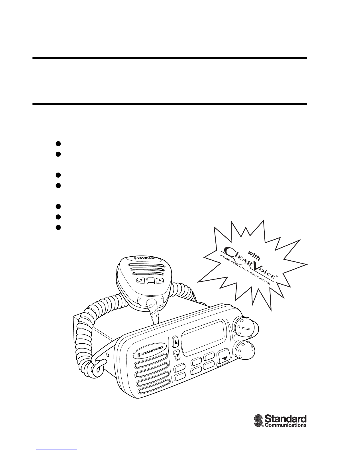
INTREPID GX1260S
25 Watt VHF/FM
Marine T ransceiver
Owner
'
s Manual
Submersible
One-Button DSC Distress Call Automatically
Sends Latitude & Longitude and Vessel ID
Noise Canceling “Clear Voice” Microphone
Latitude & Longitude Shown On Display
When Connected To GPS
Programmable Scan & Priority Ch16 Scan
NOAA Weather Alert
Backlit LCD & Keys
a division of
Page 2

TABLE OF CONTENTS
FCC NOTICE.................................................................................................... 1
1 GENERAL INFORMATION.............................................................................. 2
INTRODUCTION .............................................................................................. 2
FCC/ INDUSTRY CANADA INFORMATION.................................................... 2
2 ACCESSORIES ............................................................................................... 3
PACKING LIST ................................................................................................. 3
OPTIONS ......................................................................................................... 3
3 CONTROLS AND INDICATORS ..................................................................... 4
CONTROLS AND CONNECTIONS ................................................................. 4
4 INSTALLATION ............................................................................................... 8
LOCATION ....................................................................................................... 8
ELECTRICAL CONNECTIONS ........................................................................ 8
ACCESSORY CABLE ...................................................................................... 9
Cable pin number and signal ..................................................................... 9
CMB16 FLUSH MOUNT INSTALLATION ...................................................... 10
5 BASIC OPERATION ...................................................................................... 11
RECEPTION................................................................................................... 11
TRANSMISSION ............................................................................................ 11
TRANSMIT TIME - OUT TIMER (TOT) .......................................................... 12
SIMPLEX/DUPLEX CHANNEL USE .............................................................. 12
USA, CANADA, AND INTERNATIONAL MODE ............................................ 12
NOAA WEATHER CHANNELS ...................................................................... 13
NOAA WEATHER ALERT .............................................................................. 13
MEMORY SCANNING ................................................................................... 14
CH16 PRIORITY SCANNING (PRI-SCAN) .................................................... 14
POSITION INDICATION................................................................................. 15
RESETTING THE TRANSCEIVER’S MICROPROCESSOR ......................... 15
6 DIGITAL SELECTIVE CALLING ................................................................... 16
GENERAL ...................................................................................................... 16
SENDING A DISTRESS CALL ....................................................................... 16
SENDING AN INDIVIDUAL CALL .................................................................. 17
SENDING AN ALL SHIP CALL ...................................................................... 18
DSC STANDBY .............................................................................................. 19
CALL WAITING DIRECTORY ........................................................................ 20
Operation of Distress Call Waiting ........................................................... 20
Operation of Individual Call Waiting ......................................................... 21
Page 3

RECEIVING DSC CALLS ............................................................................... 21
Receiving a distress call........................................................................... 21
Receiving a distress relay call .................................................................. 22
Receiving an all ships call ........................................................................ 22
Receiving a geographical area call .......................................................... 22
Receiving an individual call ...................................................................... 23
7 DSC / RADIO SETUP MODE......................................................................... 24
SETUP............................................................................................................ 24
LAMP ADJUSTING ........................................................................................ 24
LCD CONTRAST............................................................................................ 24
INDIVIDUAL DIRECTORY SETUP (DSC) ..................................................... 25
KEY BEEP ON OR OFF ................................................................................. 26
TIME OFFSET ................................................................................................ 27
USER MMSID INPUT ..................................................................................... 28
8 RAM MIC OPERATION.................................................................................. 29
RAM MIC CONTROLS AND CONNECTIONS ............................................... 29
INDICATORS ................................................................................................. 31
INTERCOM OPERATION .............................................................................. 32
Communication ........................................................................................ 32
Calling ...................................................................................................... 32
9 MAINTENANCE ............................................................................................. 33
REPLACEMENT PARTS................................................................................ 33
TROUBLESHOOTING CHART ...................................................................... 34
10 SPECIFICATIONS ......................................................................................... 35
GENERAL ...................................................................................................... 35
TRANSMITTER .............................................................................................. 35
RECEIVER ..................................................................................................... 35
Page 4

GX1260S Owner’s Manual page 1
FCC NOTICE
NOTICE
Unauthorized changes or modifications to this equipment may void
compliance with FCC Rules. Any change or modification must be
approved in writing by Standard Communications Corp.
NOTICE
This equipment has been tested and found to comply with the limits for
a Class B digital device, pursuant to Part 15 of the FCC Rules. These
limits are designed to provide reasonable protection against harmful
interference in a residential installation. This equipment generates,
uses and can radiate radio frequency energy and, if not installed and
used in accordance with the instructions, may cause harmful
interference to radio communications. However, there is no guarantee
that interference will not occur in a particular installation. If this
equipment does cause harmful interference to radio or television
reception, which can be determined by turning the equipment off and
on, the user is encouraged to try to correct the interference by one or
more of the following measures:
— Reorient or relocate the receiving antenna.
— Increase the separation between the equipment and receiver.
— Connect the equipment into an outlet on a circuit different from
that to which the receiver is connected.
— Consult the dealer or an experienced radio/TV technician for
help.
Page 5

page 2 Owner’s Manual GX1260S
1 GENERAL INFORMATION
1.1 INTRODUCTION
The Standard Communications Corp. (SCC) GX1260S is a VHF/FM
transceiver designed for use in the frequency range of 156.025 to 163.275
MHz. It requires 13.8V for operation and has a switchable RF output power
of 1 watt or 25 watts.
The transceiver is capable of RTCMSC101 DSC (Digital Selective Calling)
operation and intercom operation with the use of an optional CMP23
(remote-control speaker/microphone with display).
The transceiver operates on all currently-allocated marine channels which
are switchable for use with either USA, International, or Canadian
regulations. It has an emergency channel 16 which can be immediately
selected from any channel by pressing the red 16/9 key. NOAA Weather
channels can also be accessed immediately by pressing the WX key with
channel selection.
Other features of the transceiver include: scanning, priority scanning,
submersible noise-canceling mic, high and low voltage warning, and GPS
repeatability.
1.2 FCC/ INDUSTRY CANADA INFORMATION
The following data pertaining to the transceiver is necessary to fill out the
license application.
Type Acceptance ................................................................... FCC Part 80
Output Power .......................................... 1 Watt (low) and 25 Watts (high)
Emission.....................................................................16K0F3E, 16K0G3E
Frequency Range ............................................... 156.025 to 157.425 MHz
FCC Type Number .................................................................... APV09981
Industry Canada Type Approval ..........................................363822202AV
Additional FCC and Industry Canada data, including licensing
requirements, are contained in the companion document titled
OWNER’S MANUAL SUPPLEMENT. The document also contains
charts for VHF channel assignments, transceiver procedures,
maintenance, factory service information, and warranty data.
Page 6

GX1260S Owner’s Manual page 3
2 ACCESSORIES
2.1 PACKING LIST
When the package containing the transceiver is first opened, please check
it for the following contents:
• GX1260S INTREPID Transceiver (White/Black)
• CMP349W/CMP349B (White/Black Microphone attached to the
transceiver) and hanger kit
• Mounting Bracket and hardware
• Spare Fuse (6 A, 250 V )
• Owner’s Manual
• Owner’s Manual Supplement
• Accessory Cable
• Power Card
2.2 OPTIONS
CMB16 ...................................................................... Flush-Mount Bracket
CMP23 ........................................ Remote-Access Microphone (RAM Mic)
CAW23............................................ 10-foot Extension Cable for RAM Mic
101S......................................................................Mini Extension Speaker
201S............................................................................. Extension Speaker
201SZ...................................................... Flush Mount Extension Speaker
DC60 ....................................................................................... Dust Cover
Page 7

page 4 Owner’s Manual GX1260S
3 CONTROLS AND INDICATORS
NOTE
This section defines each control of the transceiver. See Figure 1 for
location of controls. For detailed operating instructions refer to chapter
4 of this manual.
3.1 CONTROLS AND CONNECTIONS
q POWER SWITCH/VOLUME CONTROL
Turns the transceiver on and off as well as adjusts the audio volume. To
turn the transceiver on press and hold this knob until the LCD turns on.
Turn it off, press and hold this knob until the LCD turns off. When the
power is turned on, the transceiver is set to the last selected channel.
Secondary Use
When the transceiver is turned on while the SCAN and WX keys are held
down, the internal microprocessor is reset. This clears the memory and all
user-programmed settings, such as scan memory, assignments. This
condition is known as the default condition, the same as when shipped
from the factory. For a list of these defaults, see the section on Resetting
the Transceiver’s Microprocessor.
NOTE
Resetting the microprocessor will not erase DSC MMSID and
Directory Call Waiting information.
w SQUELCH CONTROL (SQL)
Sets the point at which random noise on the channel does not activate
the audio circuits but a received signal does. This point is called the
squelch threshold. Further adjustment of the squelch control will
degrade reception of wanted transmissions.
e KEY PAD
16/9 Key
Immediately recalls channel 16 from any channel location. Holding
down this key recalls channel 9.
Secondary use
Please see secondary use for the WX key.
Page 8
GX1260S Owner’s Manual page 5
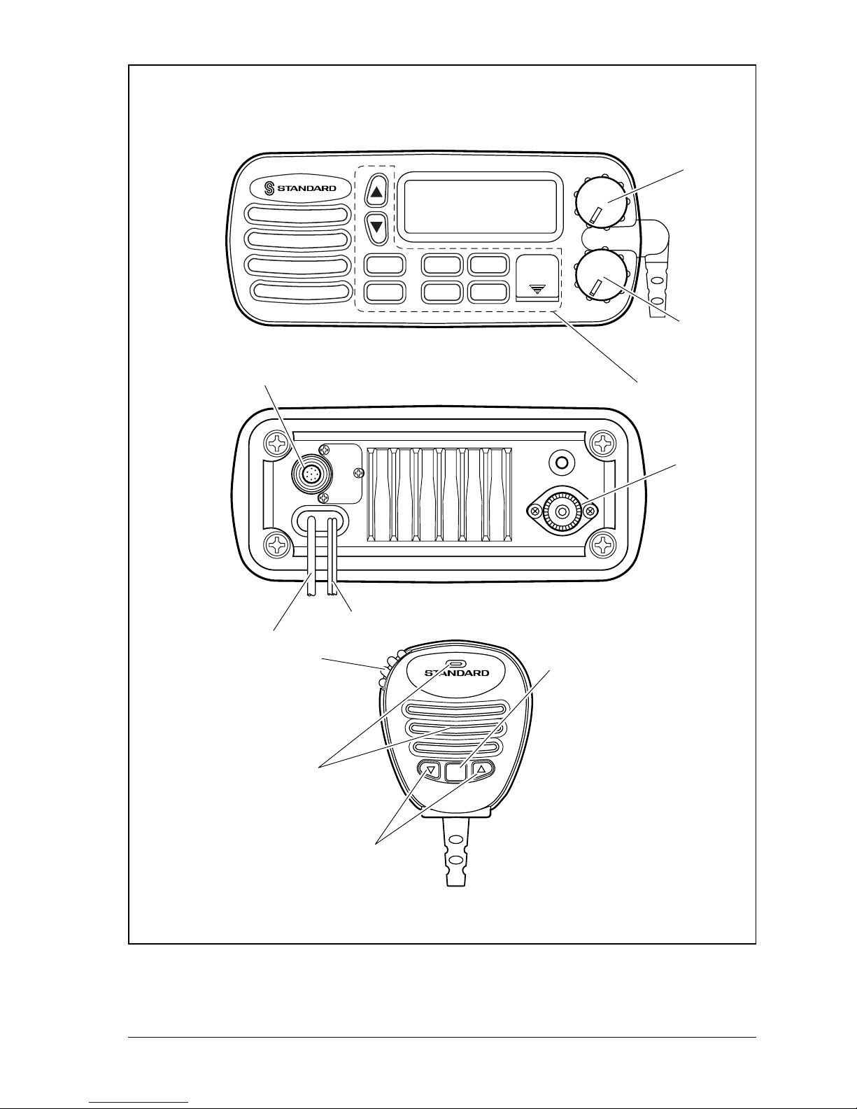
Figure 1. Controls and Connectors
SQL
VOL/PWR
16/9
POS
SCAN
WX
CALL
/SET
H/L
16/9
Horizon
INTREPID
DISTRESS
PULL OPEN
q
w
e
r
t
y
u
i
o
!0
!1
Page 9

page 6 Owner’s Manual GX1260S
WX Key
Immediately recalls the previously selected NOAA weather channel
from any channel location.
Secondary use
1. Holding down the 16/9 key while pressing the WX key changes the
mode from USA to International or Canadian.
2. Holding down the WX and SCAN key while turning the power on resets
the microprocessor and erases scan channels from memory. This clears
the memory and establishes the factory-set defaults. For a list of these
defaults, see the section on Resetting the Transceiver’s Microprocessor.
SCAN Key
1. Starts and stops scanning of programmed channels.
2. If held while the UP or DOWN key is pressed, the radio will show the
channels in scan memory. This functions will not work if the unit is scanning.
Secondary use
Press and hold the SCAN key to add the selected channel into the
transceiver’s scan memory. To delete the channel from scan memory,
press and hold the SCAN key until the MEM disappears from the LCD.
DISTRESS Key
To send the distress call see section 6.2, (Sending a Distress Call).
CALL/SET Key
The CALL/SET key functions as the enter key.
Secondary use
P ress the CALL/SET key to access the DSC OPERATION menu. The
following DSC functions can be accessed from the DSC OPERATION
menu; INDIVIDUAL, ALL SHIPS, STANDBY, and CALL WAIT.
Press and hold the CALL/SET key to access the SETUP menu. The
following functions can be accessed in the SETUP menu; LAMP ADJUST,
CONTRAST, INDIV DIR, KEY BEEP, TIME SET, USER MMSID.
H/L Key
Toggles between high and low power. When the H/L key is pressed
while the transceiver is on channel 13 or 67, the power will temporarily
switch from LO to HI power until the PTT is pressed. The H/L key does
not function on transmit inhibited and low power only channels.
UP and DOWN Keys
The UP and DOWN keys are used to select items in the DSC
OPERATION and SETUP menus. The UP or DOWN key on the
microphone can also be used to select channels.
Page 10

GX1260S Owner’s Manual page 7
POS / IC key
1. Press the POS/IC key, when connected to a GPS receiver, to displays
position data (LAT/LON) on the LCD.
Secondary use
Press and hold the POS/IC key to activate the intercom. The intercom
feature is only possible when the optional RAM MIC (CMP23) is
connected to the transceiver.
r RAM MIC CONNECTOR
Connects the Remote Access Microphone (RAM MIC). Refer to
“section 7.0, (RAM MIC OPERATION).
t ACCESSORY CONNECTION CABLE
Connects the radio to a GPS and an external speaker.
y DC INPUT CABLE
Connects the radio to a DC power supply of 13.8V
u ANTENNA JACK
Connects an antenna to the transceiver. Use a marine VHF antenna
with an impedance of 50 ohms.
i PTT (Push-To-Talk) SWITCH
Keys the transmitter when the transceiver is in radio mode. If the
transceiver is in the intercom operation mode, it activates the
microphone for the intercom.
o CLEAR VOICE NOISE-CANCELING MICROPHONE
Transmits the voice message with reduction of background noise.
!0 UP and DOWN KEYS
The UP and DOWN function the same as the UP and DOWN keys on the
front panel of the transceiver.
!1 16/9 Key
Pressing the 16/9 key Immediately recalls channel 16 from any
location. Press and hold the 16/9 key to recall channel 9.
Page 11
page 8 Owner’s Manual GX1260S
4 INSTALLATION
4.1 LOCATION
1. The radio can be mounted at any angle. Choose a mounting
location that:
• is far enough from any compass to avoid any deviation in compass
reading due to the speaker magnet
• provides accessibility to the front panel controls
• allows connection to a power source and an antenna
• has nearby space for installation of a microphone hanger
• the antenna can be mounted at least 3 feet from radio
4.2 ELECTRICAL CONNECTIONS
CAUTION
Reverse polarity connections will damage the radio!
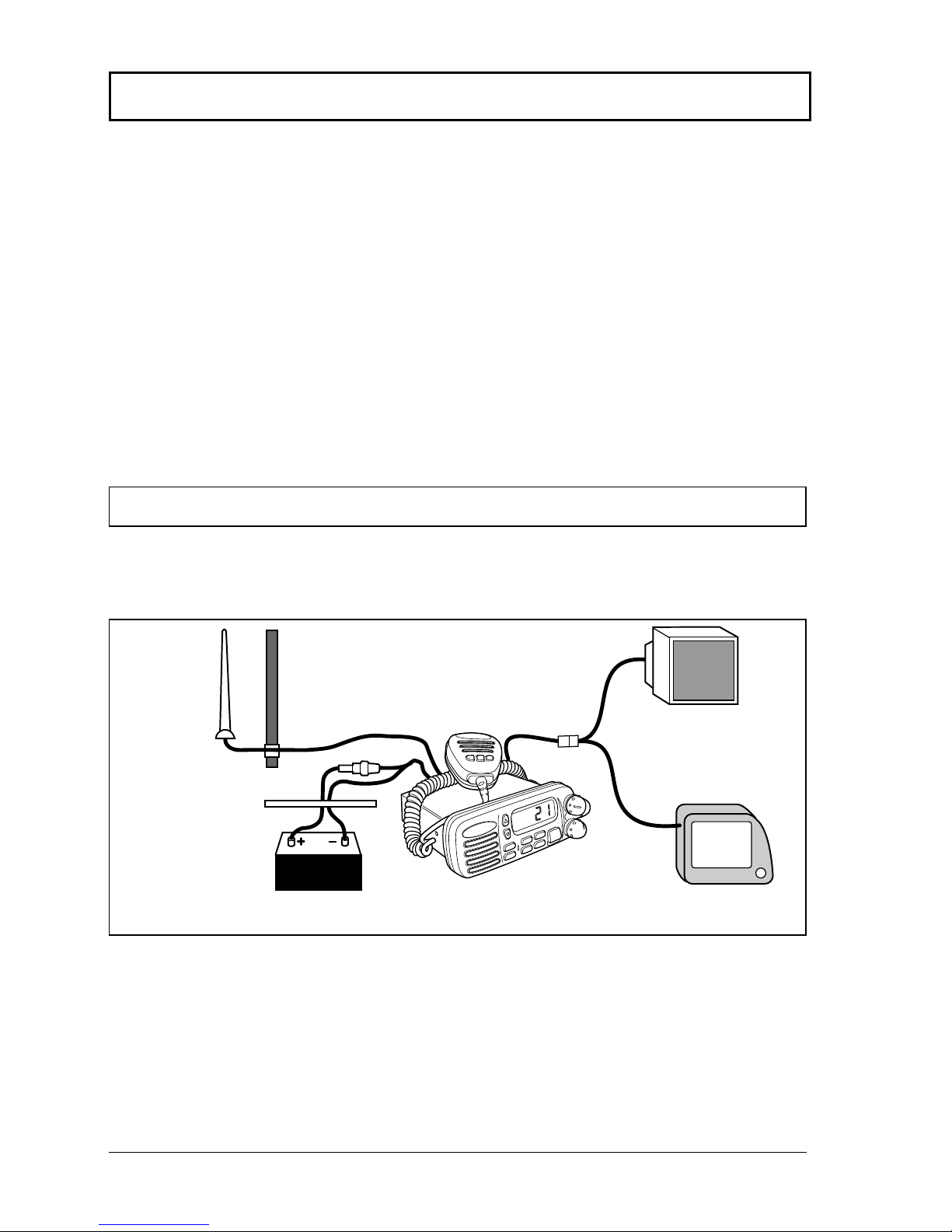
Connect the power cord and antenna to the radio. Antenna and Power
Supply connections are as follows (see Figure 2):
1. Mount the antenna at least 3 feet away from the radio. At the rear of
the radio, connect the antenna cable. It must have a PL259
connector. RG-8/U coaxial cable must be used if the antenna is 25
feet or more from the radio. RG58 cable can be used for distances
less than 25 feet.
H
I
U
S
A
A
Optional Speaker
Antenna
Water proof
Deck Outlet
Power Source
Black
Red
Fuse
Figure 2. General Installation
GPS navigation receiver
Accessory cable
Page 12
GX1260S Owner’s Manual page 9
2. Connect the red power wire to a 13.8 VDC ± 20% power source.
Connect the black power wire to a negative ground.
3. If an optional remote extension speaker is to be used, refer to
section 4.3 for connections.
4. It is advisable to have a Certified Marine Technician check the
power output and the standing wave ratio of the antenna after
installation.
12
3
67 8
45
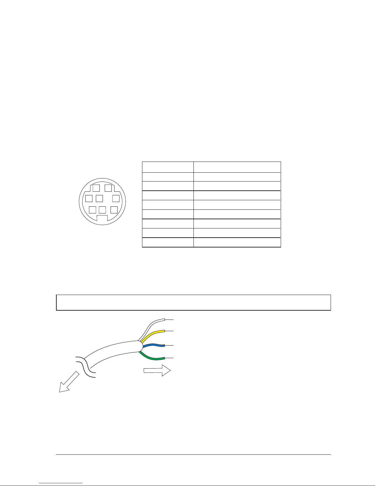
4.3 ACCESSORY CABLE
Cable pin number and signal
When connecting the external speaker or GPS navigation receiver, strip off
about 1 inch (2 cm) of the specified wire’s insulation.
NOTE
Never short wires. This may lead to malfunctions.
Pin number Signal
1 External speaker (+)
2 External speaker (–)
3 No Connection
4 NMEA IN (+)
5 No Connection
6 NMEA IN (–)
7 No Connection
8 No Connection
White: External speaker (+)
Yellow: External speaker (–)
Blue:
NMEA IN (+) of GPS navigation receiver
Green:
NMEA IN (–) of GPS navigation receiver
To external speaker and GPS receiver
To GX1260S
Page 13

page 10 Owner’s Manual GX1260S
4.4 CMB16 FLUSH MOUNT INSTALLATION
1. Make a rectangular template for the flush mount measuring 2 1/8" H
x 5 3/4" W.
2. Use the template to mark the location where the rectangular hole is
to be cut. Confirm the space behind the dash or panel is deep
enough to accommodate the transceiver (at least 6 inches deep).
There should be at least 1/2 inch between the transceiver’s heatsink
and any wiring, cables or structures.
3. Cut out the rectangular hole and insert the transceiver.
4. Fasten the brackets to the sides of the transceiver with the lock
washer nut combination, so that the mounting screw base faces the
mounting surface (see Figure 3).
5. Turn the adjusting screw to adjust the tension so that the
transceiver is tight against the mounting surface.
Bracket
Adjusting screw
Lock-washer nut combination
Figure 3. CMB16 Flush Mount Installation
Page 14

GX1260S Owner’s Manual page 11
5 BASIC OPERATION
5.1 RECEPTION
1. After the transceiver has been installed, ensure that the power
supply and antenna are properly connected.
2. Press and hold the VOL/PWR knob until the radio turns on.
3. Turn the SQL knob fully counterclockwise. This state is known as
“squelch off”.
4. Turn up the volume until noise or audio from the speaker is at a
comfortable level.
5. Turn the SQL knob clockwise until the random noise just
disappears. This state is known as the “squelch threshold.”
6. Press the UP or DOWN key to select the desired channel. Refer to
the channel chart in the OWNER’S MANUAL SUPPLEMENT for
available channels.
7. When a message is received, adjust the volume to the desired
listening level. The “BUSY” indicator in the LCD is displayed
indicating that the channel is being used.
5.2 TRANSMISSION
1. Perform steps 1 through 6 of RECEPTION.
2. Before transmitting, monitor the channel and ensure it is clear. THIS
IS AN FCC REQUIREMENT!
3. Press the PTT (push-to-talk) switch. The TX indicator on the LCD is
displayed.
4. Speak slowly and clearly into the microphone.
5. When the transmission is finished, release the PTT switch.
6. Refer to the OWNER’S MANUAL SUPPLEMENT for standard
transceiver operating procedures.
NOTE
This is a noise-canceling microphone. It should be positioned within 1
inch (2 cm) from the mouth for optimum performance.
Page 15

page 12 Owner’s Manual GX1260S
5.3 TRANSMIT TIME - OUT TIMER (TOT)
When the PTT switch on the microphone is held down, transmit time is
limited to 5 minutes. This prevents unintentional transmissions. About 10
seconds before automatic transmitter shutdown, a warning beep will be
heard from the speaker(s). The transceiver will then automatically go to
receive mode, even if the PTT switch is continually held down. Before
transmitting again, the PTT switch must first be released and then pressed
again.
5.4 SIMPLEX/DUPLEX CHANNEL USE
Refer to the OWNER’S MANUAL SUPPLEMENT for instructions on use of
simplex and duplex channels.
NOTE
All channels are factory-programmed in accordance with FCC (USA),
Industry Canada (Canada), and International regulations. Mode of
operation cannot be altered from simplex to duplex or vice-versa.
5.5 USA, CANADA, AND INTERNATIONAL MODE
1. To change the modes, hold the 16/9 key and press the WX key. The
mode changes from USA to International to Canadian with each
press of the WX key.
2. USA will be displayed on the LCD for USA mode, INTL will be
displayed for International mode, and CAN will be displayed for
Canadian mode.
3. Refer to the OWNERS MANUAL SUPPLEMENT for allocated
channels in each mode.
Page 16

GX1260S Owner’s Manual page 13
5.6 NOAA WEATHER CHANNELS
1. To receive a weather channel, press the WX key from any channel.
The transceiver will go to the last selected weather channel.
2. Press the UP or DOWN key on the microphone to select a different
weather channel.
3. To exit from the weather channels, press the WX key. The
transceiver returns to the channel it was on prior to a weather
channel.
5.7 NOAA WEATHER ALERT
In the event of extreme weather disturbances, such as storms and
hurricanes, the NOAA (National Oceanic and Atmospheric Administration)
sends a weather alert accompanied by a 1050 Hz tone and subsequent
weather report on one of the weather channels. The transceiver is capable
of receiving this alert if the following is performed:
1. Program weather channels into the transceiver’s memory for
scanning. Follow the same procedure as for regular channels under
Section 5.8.
2. Press the SCAN key once to start memory scanning or hold down
the SCAN key during memory scanning to start priority scanning.
3. The programmed weather channels will be scanned along with the
regular-programmed channels. However, scanning will not stop on
a normal weather broadcast unless a NOAA alert is received.
4. When an alert is received on a weather channel, scanning will stop
and the transceiver will emit a loud beep to alert the user of a NOAA
broadcast.
5. Press the WX key to stop the alert tone and receive the weather
report.
NOTE
If the WX key is not pressed the alert tone will be emitted for 5 minutes
and then the weather report will be received.
Page 17

page 14 Owner’s Manual GX1260S
5.8 MEMORY SCANNING
NOTE
• During scanning, the dot matrix area of the LCD will show MEMSCAN or PRI-SCAN depending on the scan mode selected.
• The channel number shown is the last channel that a transmission
was received on.
1. Adjust the SQL knob just until background noise disappears.
2. Select a desired channel to be scanned using the UP or DOWN
key. Press and hold down the SCAN key until MEM appears in the
LCD to program the channel into the transceiver’s memory.
3. Repeat step 2 for all the desired channels to be scanned.
4. To DELETE a channel from the transceiver’s memory, press and
hold down the SCAN key again until MEM disappears in the LCD.
5. To start scanning, press the SCAN key. Scanning will proceed from
the lowest to the highest programmed channel number and will stop
on a channel when a transmission is received.
6. To stop scanning, press the SCAN, 16/9, WX, or PTT key.
5.9 CH16 PRIORITY SCANNING (PRI-SCAN)
1. The priority channel is set to channel 16.
2. For priority scanning, hold down the SCAN key until PRI-SCAN
appears in the LCD during memory scanning. Scanning will
proceed between the memorized channels and the priority channel.
The priority channel will be scanned after each programmed
channel.
CH16MEM CH. CH16MEM CH.
Page 18

GX1260S Owner’s Manual page 15
5.10 POSITION INDICATION
The transceiver has the ability to display the time and date as well as the
vessel’s position (LAT/LON), if connected to a GPS receiver.
1. Press the POS key to display position
information.
2. To hide the position information, press the POS
key.
NOTE
• The TIME OFFSET should be set to local time in the DSC/RADIO
setup mode when the radio is connected the GPS navigation
receiver. To adjust TIME OFFSET to your local time, refer to section
7.6 TIME OFFSET.
5.11 RESETTING THE TRANSCEIVER’S MICROPROCESSOR
Resetting the microprocessor restores the initial, factory supplied
conditions in the transceiver. These are called the default conditions.
To reset the microprocessor, first turn the transceiver off. Then while
pressing the WX and SCAN keys, turn the transceiver on. The default
conditions are:
• No channels in SCAN memory.
• Channel 16 will be selected when the transceiver is turned on.
• WX channel 01 will be recalled when the WX key is pressed.
NOTE
Resetting the microprocessor will not erase DSC MMSID and
Directory Call Waiting information.
JUN15 08:45P
35.55. N
138.28. W
A
Page 19

page 16 Owner’s Manual GX1260S
6 DIGITAL SELECTIVE CALLING
6.1 GENERAL
6.1.1 Digital Selective Calling (DSC)
Digital Selective Calling is a semi-automated method of establishing a
radio call, it has been designated by the International Maritime
Organization (IMO) as an international standard for establishing VHF, MF
and HF radio calls. It had also been designated part of the Global Maritime
Distress and Safety System (GMDSS). It is planed that DSC will eventually
replace aural watches on distress frequencies and will be used to
announce routine and urgent maritime safety information broadcasts.
This new service will allow mariners to instantly send a distress call with
GPS position (when connected to the transceiver) to the USA Coast Guard
and other vessel within range of the transmission. DSC will also allow
mariners to initiate or receive distress, urgency, safety and routine calls to
or from another vessel equipped with a DSC transceiver.
6.1.2 Marine Mobile Service Identity (MMSID)
What is an MMSID?
An MMSID is a nine digit number used on Marine Transceiver capable of
using Digital Selective Calling (DSC). This number is used like a telephone
number to selectively call other vessels. Refer to section 7.7 (USER
MMSID INPUT).
How can I obtain a MMSID assignment?
Currently, the only way to obtain an MMSID is to apply for Ship Station
License, or an amendment to a ship station license, regardless of whether
the license is otherwise required. These procedures are currently under
review by both the FCC and US Coast Guard.
WARNING
This radio is designed to generate a digital maritime distress and
safety call to facilitate search and rescue. To be effective as a safety
device, this equipment must be used only within communication range
of a shore-based VHF marine channel 70 distress and safety watch
system. The range of signal may vary but under normal conditions
should be approximately 20 nautical miles.
Page 20

GX1260S Owner’s Manual page 17
DISTRESS
WAITING
TX HI USA
A
>DISTRESS
EXIT
A
CANCEL
DISTRESS
EXIT
A
>CANCEL
6.2 SENDING A DISTRESS CALL
The distress call automatically includes the vessel’s DSC MMSID and Lat/
Lon position. Refer to section 7.7, USER MMSID INPUT. The vessel’s
position can be sent only if the transceiver is properly connected to an
operating navigation receiver.
1. Remove the cover and press the DISTRESS
key. The distress call menu will appear on the
LCD.
Press and hold the DISTRESS key until the
distress signal is sent (see step 2)
2. When the distress signal is sent, the dot-matrix
area of the LCD will be as shown in the
illustration on the left.
After the message has been sent, the Distress
Alarm will be sounded.
3. The transceiver shadow-watches for a
transmission between CH16 and CH70 until an
acknowledgment signal is received. “DISTRESS”
and “WAITING” will appear on the LCD.
4. If no acknowledgment is received, the distress call is repeated in 4
minute intervals until an acknowledgment is received.
5. To cancel, press the DOWN key to select
CANCEL after pressing the DISTRESS key.
Then, press the CALL/SET key or turn off the
radio.
6. When a distress acknowledgment is received, a distress alarm
sounds and channel 16 is automatically selected.
7. To cancel the alarm, press any key.
NOTE
When a GPS receiver with NMEA output is connected, the vessel’s
position is automatically transmitted with the distress call.
Page 21

page 18 Owner’s Manual GX1260S
NO REPLY
BOB
>SEND
EXIT
A
HI USA
A
6.3 SENDING AN INDIVIDUAL CALL
To send an individual call, see section 7.4 INDIVIDUAL DIRECTORY
SETUP. The individual call function allows you to transmit a DSC signal to
a specific party only, prompting communication on a voice channel.
1. Select the traffic channel for voice communication.
2. Press the CALL/SET key.
The DSC CALLING menu will appear.
3. Press the UP or DOWN key to select INDIVIDUAL.
(To cancel, select EXIT with the UP or DOWN key
or press the 16/9 key.)
4. Press the CALL/SET key.
The transceiver will beep, and the individual
directory will appear.
5. Press the UP or DOWN key to select the
individual you want to contact.
6. Press the CALL/SET key to transmit the individual DSC signal.
7. After INDIVIDUAL CALL is transmitted, the
transceiver will wait 8 seconds for the
acknowledgment. If the reply signal is not
received, then the transceiver will transmit again.
8. After the second INDIVIDUAL CALL is
transmitted, if the reply signal is not received,
the dot matrix area of the LCD will display
“>SEND” to prompt the user to send the call
again or exit the mode.
9. When an individual call acknowledgment “able
to comply” is received, the established channel
is automatically selected and an alarm sounds.
>INDIVIDUAL
ALL SHIP
STANDBY
CALL WAIT
A
>TOM
MIKE
BOB
DICK
A
TOM
MIKE
>BOB
DICK
A
INDIVIDUAL
BOB
WAITING
A
HI USA
A
Page 22

GX1260S Owner’s Manual page 19
10.When an individual call acknowledgment with
“unable to comply” is received, the established
channel is automatically selected.
11. To cancel, select EXIT using the DOWN key and press the CALL/
SET key.
This procedure can be also canceled as follows;
Press the CALL/SET key or 16/9 key.
6.4 SENDING AN ALL SHIP CALL
The All Ships Call function allows contact to be established with other
vessel stations without having their ID in the individual calling directory.
Also, priority for the call can be designated as Urgency, Safety or Routine.
1. Select the traffic channel (for voice
communication).
2. Press the CALL/SET key. The DSC CALLING
menu will appear.
3. Press the UP or DOWN key to select ALL SHIP.
4. Press the CALL/SET key.
To cancel this, press the UP or DOWN key to
select EXIT.
5. Press the UP or DOWN key to select the nature
of call (URGENCY, SAFETY or ROUTINE).
6. Press the CALL/SET key to transmit the all
ships DSC signal.
7. After the ALL SHIPS CALL is transmitted, the
transceiver will wait on CH16.
>INDIVIDUAL
ALL SHIP
STANDBY
CALL WAIT
A
UNATTENED
BOB
>SEND
EXIT
A
HI USA
A
INDIVIDUAL
>ALL SHIP
STANDBY
CALL WAIT
A
>URGENCY
SAFETY
ROUTINE
EXIT
A
TX HI USA
>URGENCY
SAFETY
ROUTINE
EXIT
A
TX HI USA
A
Page 23

page 20 Owner’s Manual GX1260S
6.5 DSC STANDBY
The DSC Standby function allows the transceiver to reply to DSC calls with
the UNATTENDED message and log the calls for return at a more
convenient time. When set to the DSC Standby mode, voice traffic may still
be monitored on any selected channel.
1. Press the CALL/SET key.
The DSC CALLING menu will appear.
2. Press the UP or DOWN key to select the
STANDBY mode.
3. Press the CALL/SET key.
4. When an individual DSC call is received, the radio will respond with
the UNATTENDED message when an operator cannot answer to
the caller.
The DSC call will be logged into the radio’s call waiting directory.
5. To cancel this, press the 16/9 key.
6.6 CALL WAITING DIRECTORY
The DSC Call Waiting directory logs 10 received distress calls, and logs 20
individual calls that are received and not answered within 5 minutes or
while the radio is set on the DSC Standby function. Calls will be logged
while busy with other communications as long as the transmitter is not
keyed at the time of the call. If the call is answered within 5 minutes the call
will not be logged. When a call is logged, a message will appear.
NOTE
When a DISTRESS CALL is received, this call will be logged on the
distress call waiting directory.
>INDIVIDUAL
ALL SHIP
STANDBY
CALL WAIT
A
INDIVIDUAL
ALL SHIP
>STANDBY
CALL WAIT
A
HI USA
DSC STANDBY
UNATTENED
A
Page 24

GX1260S Owner’s Manual page 21
6.6.1 Operation of Distress Call Waiting
1. Press the CALL/SET key.
The DSC CALLING menu will appear.
2. Press the UP or DOWN key to select CALL
WAIT.
3. Press the CALL/SET key.
4. Press the UP or DOWN key to select the
DISTRESS.
5. Press the CALL/SET key to display the log data
which was received last.
6. Press the UP or DOWN key to select another logged call
7. To exit from Distress Call Waiting, press the CALL/SET key and
select EXIT. Then press the CALL/SET key again.
6.6.2 Operation of Individual Call Waiting
1. Press the CALL/SET key.
The DSC CALLING menu will appear.
2. Press the UP or DOWN key to select CALL
WAIT.
3. Press the CALL/SET key.
4. Press the UP or DOWN key to select INDIVIDUAL.
5. Press the CALL/SET key to enter the individual
log.
>INDIVIDUAL
ALL SHIP
STANDBY
CALL WAIT
A
INDIVIDUAL
ALL SHIP
STANDBY
>CALL WAIT
A
CALL WAIT
>DISTRESS
INDIVIDUAL
EXIT
A
JUN15 08:45P
ID987654321
35.55. N
138.28. W
A
CALL WAIT
>DISTRESS
INDIVIDUAL
EXIT
A
CALL WAIT
DISTRESS
>INDIVIDUAL
EXIT
A
CALL WAIT
>DISTRESS
INDIVIDUAL
EXIT
A
>INDIVIDUAL
ALL SHIP
STANDBY
CALL WAIT
A
INDIVIDUAL
ALL SHIP
STANDBY
>CALL WAIT
A
Page 25

page 22 Owner’s Manual GX1260S
DISTRESS RLY
ID366911111
35.88. N
138.20. W
DISTRESS
ID366911111
NO POSITION
DATA
6. Press the UP or DOWN key to select the name.
7. Press the CALL/SET key to display the logged
call.
8. Press the CALL/SET key to resend the INDIVIDUAL CALL.
9. To exit from Individual Call Waiting, select EXIT and press the
CALL/SET key.
10. Press the UP or DOWN key to select another logged call or to select
EXIT.
11. Press the CALL/SET key to access next logged call or EXIT.
6.7 RECEIVING DSC CALLS
Several types of DSC transmissions can be received. The required action
depends on the particular DSC type as outlined in the following examples.
NOTE
When the radio receives on working channel or transmits on working
channel, DSC calls will not be received.
6.7.1 Receiving a distress call
1. A distress call is received. An emergency alarm
sounds.
Then channel 16 is automatically selected.
2. Press any key to stop the alarm.
3. If the received distress data does not include the
position data, the LCD will show the display on
the left.
NOTE
You must continue monitoring channel 16 as a coast station may
require assistance in any rescue attempt.
6.7.2 Receiving a distress relay call
1. A distress relay call is received. An emergency
alarm sounds.
Then channel 16 is automatically selected.
2. Press any key to stop the alarm.
DISTRESS
ID366911111
35.88. N
138.20. W
JUN15 08:45P
ID987654321
A
EXIT
>SEND
>NAME1
NAME2
NAME3
NAME4
A
Page 26

GX1260S Owner’s Manual page 23
NOTE
You must continue monitoring channel 16 as a coast station may
require assistance in any rescue attempt.
6.7.3 Receiving an all ships call
1. An all ships call is received. An emergency
alarm sounds.
Then channel 16 is automatically selected.
2. Press any key to stop the alarm.
3. Monitor channel 16 or traffic channel until the URGENCY
communication has completed.
6.7.4 Receiving a geographical area call
1. A geographical call is received. An emergency
alarm sounds (different from DISTRESS). Then
the requested channel from the other ship is
automatically selected.
2. Press any key to stop the alarm.
3. Monitor the traffic channel for an announcement from the calling ship.
NOTE
This feature is only available when a GPS or LORAN receiver is
connected.
6.7.5 Receiving an individual call
When receiving an individual call, an acknowledgment must be sent back
to the calling station.
1. An individual call is received. A calling alarm
sounds.
Then the requested channel from the calling
station is automatically selected.
2. Press any key to stop the alarm.
3. Monitor the selected channel for an announcement from the calling
ship.
ALL SHIPS
ID366911111
JUN15 07:00P
GEOGRAPHICAL
ID366911111
JUN15 07:00P
INDIVIDUAL
BOB
JUN15 04:00P
Page 27

page 24 Owner’s Manual GX1260S
7.
DSC / RADIO SETUP MODE
7.1 SETUP
1. Press and hold down the CALL/SET key until
the SETUP menu appears.
2. To select the items, press the UP or DOWN key.
NOTE
The RAM MIC CMP23 cannot change the SETUP
menu. The SETUP menu is displayed in the LCD of the
CMP23 as shown in the illustration on the right.
7.2 LAMP ADJUSTING
1. Select LAMP ADJUST in the SETUP menu with
the UP or DOWN key.
2. Press the CALL/SET key.
The lamp adjusting menu will appear.
3. Press the UP or DOWN key to select the desired level.
When DARK is selected, the lamp is extinguished.
When BRIGHT is selected, the lamp is brightest.
4. Press the CALL/SET key to store the selected level.
The LCD will return to the SETUP menu.
7.3 LCD CONTRAST
1. Select CONTRAST in the SETUP menu with the
UP or DOWN key.
2. Press the CALL/SET key.
The contrast setting menu will appear. The
contrast level can be set from 1 to 7.
3. Press the UP or DOWN key to select the desired level.
(Example: 5 is selected)
The contrast is stronger as the selected level increases.
4. Press the CALL/SET key to store the selected level.
The LCD will return to the SETUP menu.
>LAMP ADJUST
CONTRAST
INDIV DIR
KEY BEEP
A
LAMP ADJUST
>CONTRAST
INDIV DIR
KEY BEEP
A
>LAMP ADJUST
CONTRAST
INDIV DIR
KEY BEEP
A
>BRIGHT
DIM
DARK
A
BRIGHT
DIM
>DARK
A
CONTRAST
1
A
CONTRAST
5
A
Page 28

GX1260S Owner’s Manual page 25
7.4 INDIVIDUAL DIRECTORY SETUP (DSC)
1. Press and hold the CALL/SET key until the
SETUP menu is displayed.
2. Select INDIVI DIR by using the UP or DOWN key.
3. Press the CALL/SET key to enter the individual
directory.
4. Press the UP or DOWN key to set the desired
address number.
The address number can be set from 01 to 30.
5. Press the CALL/SET key to store the address
number.
6. Press the UP or DOWN key to scroll through the alphabet.
7. Press the CALL/SET key to enter the desired
letter and move the cursor one space to the
right. Repeat procedure until the name is
complete. The name can consist of up to eleven
characters, if you do not use all eleven
character press the CALL/SET key to move to
the next space. This method can be used to
enter a blank space in the name.
8. After the eleventh letter or space has been entered, press the
CALL/SET key to advance to the MMSID (Maritime Mobile Service
Identity Number) number entry.
9. Press the UP or DOWN key to scroll through the number, 0-9. To
enter the desired number and move one space to the right press the
CALL/SET key. Repeat procedure until all nine space of MMSID
number are entered.
LAMP ADJUST
CONTRAST
>INDIV DIR
KEY BEEP
A
NAME
––––––––
––––––––
MIMSID
NAME
––––––––
MIMSID
––––––––
NAME
––––––––
MIMSID
B–––––––
NAME
––––––––
MIMSID
BO––––––
NAME
––––––––
––––––––
MIMSID
Page 29

page 26 Owner’s Manual GX1260S
10.After entering the MMSID number press and
hold the CALL/SET key until the screen
prompts you to select NEXT or EXIT.
11. To enter another individual address select NEXT with the UP or DOWN
key and press the CALL/SET key. Repeat steps 4 through 10.
12. To exit the individual directory setup, select with the UP or DOWN
key and press the CALL/SET key.
NOTE
Selecting NEXT or EXIT will automatically save the name and MMSID
number into memory.
7.5 KEY BEEP (ON OR OFF)
1. Select KEY BEEP in the SETUP menu with the
UP or DOWN key.
2. Press the CALL/SET key.
The key beeps setting menu will appear.
3. Press the UP or DOWN key to select ON or OFF.
4. Press the CALL/SET key to set the key beep condition.
The LCD will return to the SETUP menu.
NOTE
Emergency alarm and beeps for DSC operation cannot be turned
OFF.
LAMP ADJUST
CONTRAST
INDIV DIR
>KEY BEEP
A
OFF
A
>ON
BOB
123456789
>NEXT
EXIT
Page 30

GX1260S Owner’s Manual page 27
7.6 TIME OFFSET
Sets the time difference between local time and UTC. Time is displayed
when position (LAT/LON) is displayed by pressing the POS key.
1. Select TIME SET in the SETUP menu with the
UP or DOWN key.
2. Press the CALL/SET key.
The time offset menu appears.
3. Press the UP or DOWN key to select time offset
from UTC.
See Figure 4 to find your offset time from UTC.
If 00:00 is assigned, the time is the same as
UTC (Universal Time Coordinated) or GMT
(Greenwich Mean Time)
4. Press the CALL/SET key to store the time offset.
The LCD will return to the SETUP menu.
0 +1 +2 +3 +4 +5 +6 +7 +8 +9 +10 +11 +12-1-2-3-4-5-6-7-8-9-10-11-12
+30
+30
+7
+7
+9
+30
+6
+5
+2
+3
UTC/GMT
CONTRAST
INDIV DIR
KEY BEEP
>TIME SET
A
00 : 00
A
TIME SET
– 08 : 00
A
TIME SET
Figure 4. Offset time table
Page 31

page 28 Owner’s Manual GX1260S
7.7 USER MMSID INPUT
1. Select the USER MMSID in the SETUP menu
with the UP or DOWN key.
2. Press the CALL/SET key.
The user MMSID menu will appear, and the first
space will blink.
3. Press the UP or DOWN key to set the number
(0 to 9 ).
4. Press the CALL/SET key to store the set
number.
The blinking number is stored, and the next
space will blink.
5. Repeat steps 3 and 4 to set your MMSID.
6. When the last number of your MMSID is in place, press and hold
down the CALL/SET key to store your MMSID.
NOTE
User MMSID can be input only twice. If the user tries
to input MMSID more than twice, the radio will show
the display on the right. If the user needs to change
the MMSID more than twice, the transceiver will have
to be sent to Factory Service. Refer to the Owner’s
Manual Supplement for address.
INDIV DIR
KEY BEEP
TIME SET
>USER MMSID
A
USER MMSID
A
––––––––
USER MMSID
A
0–––––––
USER MMSID
A
0–––––––
USER MMSID
A
012345678
ERROR TOO
PRESS
CALL/SET KEY
A
MANY ENTRIES
Page 32

GX1260S Owner’s Manual page 29
8 RAM MIC OPERATION
If the optional RAM Mic (CMP23) is connected to the remote microphone
connector on the transceiver’s rear panel, then the transceiver can use the
remote control operation except for a few functions. The RAM Mic has a
maximum range of 50 feet (15 m) with the use of two 10-foot extension
cables (CAW23). The intercom operation can be used between the RAM
Mic and the transceiver.
8.1 RAM MIC CONTROLS AND CONNECTIONS
POWER SWITCH (PWR)
Turns the transceiver on and off.
Press and hold down the PWR key until the LCD turns on. To turn the
transceiver off with the RAM Mic, press and hold the PWR key until the
LCD turns off.
SQUELCH KEY (SQL)
Activates the squelch adjusting mode.
Press this key to activate the squelch adjusting mode. Press the
or
key to adjust the squelch.
Sets the point at which random noise on the channel does not activate the
audio circuits but a received signal does. This point is called the “squelch
threshold”. Further adjustment of the squelch control by pressing the
key will degrade the reception of wanted transmissions.
When the
key is pressed and held down for 1 second or more, the
squelch is turned off.
VOLUME KEY (VOL)
Activates the volume adjusting mode.
Press this key to activate the volume adjusting mode. Press the
or
key to adjust the volume.
PTT (Push-To-Talk) SWITCH
Activates transmission.
16/9 KEY
Immediately recalls channel 16 from any channel location. Press and hold the
16/9 key to recall channel 9. Recalls the previous channel when the 16/9 key
is pressed again. When holding down the 16/9 key while pressing the WX key,
the mode toggles between USA, International and Canadian.
Page 33

page 30 Owner’s Manual GX1260S
A/B Key
This key is unavailable for this radio.
IC Key
Activates the intercom mode between the RAM Mic and the transceiver.
Refer to section 8.3, INTERCOM OPERATION.
WX Key
Immediately recalls a weather channel from any channel location. Recalls
the previous channel when the WX key is pressed again.
Secondary use
When holding down the 16/9 key while pressing the WX key, the mode
toggles between USA, International and Canadian.
SCAN Key
1. Starts and stops scanning of programmed channels.
2. If held while the UP or DOWN key is pressed, the radio will show the
channels in scan memory. This function will not work if the unit is scanning.
Secondary use
Press and hold the SCAN key to add the selected channel into the
transceiver’s scan memory for scanning MEM will appear on the LCD to
indicate that the channel has been entered into scan memory. To delete
the channel from scan memory, press and hold the SCAN key until the
MEM disappears from the LCD.
NOTE
If the transceiver is in the MEM-SCAN mode, then the RAM Mic is in
SC mode. If the transceiver is in PRI-SCAN mode, then the RAM Mic
is in PS mode.
SQL VOL PWR
16/9
WX
A/B
SCAN
IC H/L
MIC
LAMPLAMP
CALLCALL
Figure 5. CMP23 RAM Mic
Page 34

GX1260S Owner’s Manual page 31
DOWN KEY ( )
Selects the desired channel and adjusts the volume and squelch levels.
Each press decreases the channel number, volume level and squelch
level. When held down, the channels or levels decrease continuously.
UP KEY ( )
Selects the desired channel and adjusts the volume and squelch levels.
Each press increases the channel number, volume level, and squelch
level. When held down, the channels or levels increase continuously.
Secondary use
When holding down the 16/9 key while pressing the UP
key, changes the
brightness (3 levels) of the LCD back light.
H/L KEY
Toggles between high and low power. When the H/L key is pressed while
the transceiver is on Canadian channel 13, USA channel 13 or 67, the
power will temporarily switch from LO to HI power until the PTT switch is
pressed. The H/L key does not function on transmit-inhibited and low
power-only channels.
8.2 INDICATORS
Channel Display
Displays the operating channel in both transmission and reception mode.
A Indicator
A simplex channel in USA or Canadian mode whose counterpart in the
International mode is a duplex channel.
TX/ BUSY Indicator
“TX” is displayed in transmitting mode. “BUSY” is displayed in receiving
mode.
USA/ INTL/ CAN Indicator
The mode of operation. “USA” indicates USA mode. “INTL” indicates
International mode and “CAN” indicates Canadian mode.
WX Indicator
MEMMEM
A
H
L
S
D
INTLTL
USAUSA
CANCAN
SQLSQL
VOLVOL
BUSYTX
Page 35

page 32 Owner’s Manual GX1260S
A weather channel.
MEM Indicator
The channel is in the transceiver’s scan memory.
H/L Indicator
“H” is high power. “L” is low power. Blank is a reception only channel.
SQL/VOL Indicator
“SQL” is squelch adjusting mode. “VOL” is volume adjusting mode.
8.3 INTERCOM OPERATION
8.3.1 Communication
1. Press the IC key in the radio mode. The mode is changed to the
INTERCOM mode. If the IC key is pressed again the mode will
revert to radio mode.
2. “IC” is displayed on both the transceiver and the RAM Mic when the
intercom operation is activated.
3. Press the PTT switch. The “TX” indicator is displayed.
NOTE
A warning beep is emitted when the RAM Mic PTT switch is pressed
while the transceiver microphone’s PTT switch is pressed.
4. Speak slowly and clearly into the microphone, hold the microphone
about 1/2 inch away from your mouth.
5. When finished, release the PTT switch.
8.3.2 Calling
1. Hold down the IC key in the intercom operation for 1 second or
more. A calling beep is emitted twice from the transceiver speaker.
16/9WXA/B
SCAN
IC H/L
MIC
LAMP
CALL
SUBMERSIBLE
H
o
r
iz
o
n
R
A
M
m
ic
EXTERNAL
SPEAKER
RAM Mic
NOTE:
If the RAM Mic is connected to
the transceiver, the external
speaker volume is controlled
by the RAM Mic. If the RAM
Mic is not connected to the
transceiver, the external
speaker volume is controlled
by the radio.
Figure 6. Intercom operation
Page 36

GX1260S Owner’s Manual page 33
9 MAINTENANCE
The inherent quality of the solid-state components used in this transceiver
will provide many years of continuous use. Taking the following
precautions will prevent damage to the transceiver.
* Never key the microphone unless an antenna or suitable dummy load is
connected to the transceiver.
* Ensure that the supply voltage to the transceiver does not exceed 16
VDC or fall below 11 VDC.
In the unlikely event of serious problems, please contact your SCC Dealer
or our repair facility. Address and phone numbers for this facility, as well as
warranty information, are contained in your Owner’s Manual Supplement.
9.1 REPLACEMENT PARTS
Occasionally an owner needs a replacement mounting bracket or knob.
These can be ordered from our Parts Department by writing or calling:
Standard Communications Corp. Parts Department
P.O. Box 92151
Los Angeles, CA 90009-2151
Telephone 800-366-8431
Commonly requested parts, and their part numbers are listed below.
Microphone, White (CMP349W+) .............................. MP51000380
Microphone, Black (CMP349B+)................................ MP51000390
RAM Microphone Connector Cover ........................... 389B053010
Standard Mounting Bracket, White ............................ 444X160030
Standard Mounting Bracket, Black............................. 444X160130
Standard Mounting Bracket Knob, White ................... 444X154030
Standard Mounting Bracket Knob, Black ................... 444X154130
Volume Control Knob ................................................. 444X154500
Squelch Control Knob ................................................ 444X154500
Accessory Cable ........................................................ ZD0070002R
Distress Key Cover .................................................... 444X053010
Power Cord ................................................................ ZC0130001R
Mic Hanger, White...................................................... 277X155020
Mic Hanger, Black ...................................................... 277X155120
Page 37

page 34 Owner’s Manual GX1260S
PROBABLE
CAUSE
No DC voltage to the
transceiver, or blown
fuse.
Reversed power wires.
Engine noise.
External cable
Antenna.
The power supply
voltage is too high or
too low.
External cable.
Setting of the GPS
navigation receiver.
REMEDY
Press and hold the Power switch/
Volume control knob until the
transceiver turns on.
Check the power cable for DC voltage,
or replace the fuse (6A 250V).
Make sure the red wire is connected to
the positive battery post and the black
wire is connected to the negative. If
the fuse still blows, contact your SCC
Dealer.
Reroute the DC power cables away
from the engine. Add noise
suppressor on power cable. Change
to resistive spark plug wires and/or
add an alternator whine filter.
Check the polarity of the connected
external cable.
Have the antenna checked or test the
transceiver with another antenna. If
the problem persists, contact your
SCC Dealer for servicing.
Confirm that the connected power
supply voltage is not 24 volts or lower
than 9 volts. Confirm that the
generator has not malfunctioned.
Check the polarity of the connected
external cable.
Check the output signal format of the
GPS navigation receiver. This radio
requires NMEA0183 format with GLL
sentence as an output signal.
SYMPTOM
Transceiver fails to
power up.
Transceiver blows fuse
when connected to
power supply.
Popping or whining noise
from the speaker while
engine runs.
Sound is not emitted from
the external speaker.
Receiving stations report
low transmit power, even
with transceiver set to HI
power.
“HI BATTERY” or “LOW
BATTERY”is blinking
when the power is turned
on.
Your position is not
displayed.
TROUBLESHOOTING CHART
9.2 TROUBLESHOOTING CHART
LO USA
HI BATTERY
A
Page 38

GX1260S Owner’s Manual page 35
10 SPECIFICATIONS
Performance specifications are nominal, unless otherwise indicated, and
are subject to change without notice.
10.1 GENERAL
Channels ...........................................All USA, International and Canadian
Input Voltage .................................................................. 13.8 VDC +/-20%
Current Drain
Standby ........................................................................................ 0.5A
Receive ........................................................................................ 1.5A
Transmit .................................................................. 6A (Hi); 1.7A (Lo)
Dimensions .................................................... 2.76" H x 6.46" W x 7.13" D
(70 H x 164 W x 181 D mm)
Flush-Mount Dimensions .................................. 2" H x 5-5/8" W x 5-1/4" D
(51 H x 143 W x 133 D mm)
Weight ............................................................................ 2.13 Lb. (0.97 kg)
10.2 TRANSMITTER
Frequency Range ............................................... 156.025 to 157.425 MHz
RF Output.................................................................... 25 W (Hi); 1 W (Lo)
Conducted Spurious Emissions .............................. 80 dB (Hi); 60 dB (Lo)
Audio Response..................... within +1/-3 of a 6 dB/octave pre-emphasis
characteristic at 300 to 3000 Hz
Audio Distortion.................................................................................... 5 %
Modulation .................................................. 16K0G3E, for DSC 16K0G2B
Frequency Stability (-20° to +50°C) ........................................ +/- 0.0005%
FM Hum and Noise ........................................................................... 50 dB
10.3 RECEIVER
Frequency Range ............................................... 156.050 to 163.275 MHz
Sensitivity:
20 dB Quieting ........................................................................ 0.40 µV
12 dB SINAD...........................................................................0.30 µV
Squelch Sensitivity (Threshold) ..................................................... 0.13 µV
Modulation Acceptance Bandwidth ............................................. ± 7.5 kHz
Selectivity:
Spurious and Image Rejection ................................................. - 70 dB
Intermodulation and Rejection at 12 dB SINAD ....................... - 70 dB
Audio Output ........................................................................................ 4 W
Audio Response.......................................... within + 2/–8 of a 6 dB/octave
de-emphasis characteristic at 300 to 3000 Hz
Frequency Stability (-20° to +50°C) .......................................... ±0.0005 %
Channel Spacing............................................................................. 25 kHz
DSC Format .......................................................................... RTCMSC101
Page 39

Standard Communication Corp.
P.O. Box 92151
Los Angeles, CA 90009-2151
Telephone 310/532-5300
© STANDARD COMMUNICATIONS CORP. 1999
All Rights Reserved
Printed in Japan
01/00 MIT 437B851013
 Loading...