

Standard Horizon HX850S Owner's Manual
HX850S
Floating Marine Transceiver with GPS
Owner’s Manual
Page 1HX850S

TABLE OF CONTENTS
RF EXPOSURE SAFETY STATEMENT .................................................................................... 5
FCC AND CANADA RADIO LICENSE INFORMATION ........................................................... 6
MARITIME STATION LICENSE ............................................................................................ 6
MARINE RADIO CALL SIGN ................................................................................................ 6
CANADIAN SHIP STATION LICENSING ............................................................................... 6
FCC / INDUSTRY CANADA INFORMATION ........................................................................6
FCC NOTICE ................................................................................................................................ 7
1 GENERAL INFORMATION .................................................................................................... 8
1.1 INTRODUCTION ......................................................................................................... 8
2 ACCESSORIES ...................................................................................................................... 9
2.1 PACKING LIST ........................................................................................................... 9
2.2 OPTIONS ..................................................................................................................... 9
3 ABOUT THIS RADIO .......................................................................................................... 10
3.1 ABOUT THE VHF MARINE BAND .........................................................................10
4 GETTING STARTED ............................................................................................................ 11
4.1 RADIO CARE ............................................................................................................ 11
4.2 BATTERIES AND CHARGERS ............................................................................... 11
4.2.1 BATTERY SAFETY ........................................................................................ 11
4.2.2 BATTERY INSTALLATION / REMOVAL..........................................................13
4.2.3 BATTERY LIFE INFORMATION....................................................................13
4.2.4 BATTERY CHARGING ................................................................................... 14
4.2.5 USING THE CD-38 CHARGER CRADLE .................................................... 14
4.3 CONNECTING A CHART PLOTTER TO THE CD-38 .........................................15
5 CONTROLS AND SWITCHES............................................................................................ 16
6 BASIC OPERATION ............................................................................................................ 20
6.1 PROHIBITED COMMUNICATIONS ......................................................................... 20
6.2 INITIAL SETUP .........................................................................................................20
6.3 RECEPTION ..............................................................................................................20
6.4 TRANSMISSION ....................................................................................................... 21
6.4.1 TRANSMIT TIME-OUT TIMER (TOT) ........................................................... 22
6.5 DISPLAYING THE GPS RECEIVING DATA .......................................................... 22
6.6 USA, CANADA, AND INTERNATIONAL CHANNELS ............................................. 23
6.7 SIMPLEX/DUPLEX CHANNEL USE ....................................................................... 23
6.8 NOAA WEATHER CHANNELS ............................................................................... 24
6.8.1 NOAA WEATHER ALERT .............................................................................24
6.8.2 NOAA WEATHER ALERT TESTING ............................................................24
6.9 SCANNING ................................................................................................................25
6.9.1 SELECTING THE SCAN TYPE ................................................................... 25
6.9.2 MEMORY SCANNING (M-SCAN) .................................................................. 25
6.9.3 PRIORITY SCANNING (P-SCAN) ................................................................. 26
6.10 DUAL WATCH ........................................................................................................... 27
6.11 EMERGENCY (CHANNEL 16 USE) ..........................................................................28
6.12 CALLING ANOTHER VESSEL (CHANNEL 16 OR 9) .............................................28
6.13 OPERATING ON CHANNEL 13 ............................................................................. 29
6.14 OPERATING ON CHANNEL 67 ............................................................................. 29
6.15 ENABLING S.O.S STROBE OPERATION ..............................................................30
7 DIGITAL SELECTIVE CALLING ........................................................................................ 31
7.1 GENERAL .................................................................................................................. 31
7.2 MARITIME MOBILE SERVICE IDENTITY (MMSI) ................................................ 31
7.2.1 WHAT IS AN MMSI? ..................................................................................... 31
7.2.2 PROGRAMMING THE MMSI ........................................................................32
7.3 DSC DISTRESS ALERT .......................................................................................... 33
7.3.1 TRANSMITTING A DSC DISTRESS ALERT .............................................. 33
7.3.2 RECEIVING A DSC DISTRESS ALERT ..................................................... 35
7.4 ALL SHIPS CALL ..................................................................................................... 36
7.4.1 TRANSMITTING AN ALL SHIPS CALL .......................................................36
7.4.2 RECEIVING AN ALL SHIPS CALL .............................................................. 37
HX850SPage 2

TABLE OF CONTENTS
7.5 INDIVIDUAL CALL ....................................................................................................37
7.5.1 SETTING UP THE INDIVIDUAL / POSITION CALL DIRECTORY ............. 37
7.5.2 SETTING UP INDIVIDUAL REPLY .............................................................. 38
7.5.3 SETTING UP INDIVIDUAL / GROUP CALL RINGER ................................ 39
7.5.4 TRANSMITTING AN INDIVIDUAL CALL ..................................................... 40
7.5.5 RECEIVING AN INDIVIDUAL CALL .............................................................41
7.6 CALL WAITING DIRECTORY .................................................................................. 42
7.6.1 ENABLING THE CALL WAITING FEATURE .............................................. 42
7.6.2 REVIEWING RECEIVED CALLS
LOGGED INTO THE CALL WAITING DIRECTORY ..................................42
7.6.3 TO DELETE THE RECEIVED LOG
7.7 GROUP CALL ........................................................................................................... 44
7.8 POSITION REQUEST .............................................................................................. 48
7.9 POSITION REPORT ................................................................................................. 51
8 RADIO SETUP ..................................................................................................................... 54
8.1 DISPLAY .................................................................................................................... 54
8.2 DIMMER .................................................................................................................... 55
8.3 CONTRAST ............................................................................................................... 55
8.4 LAMP .........................................................................................................................56
8.5 PRIORITY CHANNEL ............................................................................................... 56
8.6 SCAN TYPE .............................................................................................................. 57
8.7 SCAN RESUME ....................................................................................................... 57
8.8 KEY BEEP ................................................................................................................ 58
8.9 WEATHER ALERT .................................................................................................... 58
8.10 CHANNEL NAME ..................................................................................................... 59
8.11 LED SETUP .............................................................................................................. 60
9 GPS SETUP ......................................................................................................................... 62
9.1 UNIT POWER ...........................................................................................................62
9.2 POWER SAVE MODE ............................................................................................. 62
9.3 COORDINATE SYSTEM ..........................................................................................63
9.4 TIME OFFSET .......................................................................................................... 64
9.5 TIME DISPLAY ......................................................................................................... 65
9.6 TIME FORMAT ......................................................................................................... 65
9.7 SOG UNIT ................................................................................................................ 66
9.8 POS DATA PRIORITY ............................................................................................. 66
9.9 NMEA OUTPUT ........................................................................................................67
9.10 ALTITUDE UNIT ....................................................................................................... 67
10 MAINTENANCE .................................................................................................................... 68
10.1 GENERAL .................................................................................................................. 68
10.2 REPLACEMENT PARTS .......................................................................................... 68
10.3 FACTORY SERVICE ................................................................................................ 69
10.4 TROUBLESHOOTING CHART ................................................................................ 69
11 CHANNEL ASSIGNMENTS ................................................................................................. 70
12 WARRANTY ..........................................................................................................................76
13 INSTALLATION OF OPTION .............................................................................................. 79
13.1 FBA-38 ALKALINE BATTERY CASE ..................................................................... 79
14 SPECIFICATIONS................................................................................................................. 80
14.1 GENERAL .................................................................................................................. 80
14.2 TRANSMITTER ......................................................................................................... 80
14.3 RECEIVER ................................................................................................................ 81
14.4 GPS ........................................................................................................................... 81
FROM THE “DSC LOG” DIRECTORY .........................................................43
7.7.1 SETUP A GROUP CALL .............................................................................. 44
7.7.2 TRANSMITTING A GROUP CALL ............................................................... 45
7.7.3 RECEIVING A GROUP CALL ...................................................................... 47
7.8.1 SETTING UP POSITION REPLY ................................................................. 48
7.8.2 TRANSMITTING A POSITION REQUEST TO ANOTHER VESSEL ........ 49
7.8.3 RECEIVING A POSITION REQUEST .......................................................... 50
7.9.1 SETTING UP A POSITION REPORT RINGER .......................................... 51
7.9.2 TRANSMITTING A DSC POSITION REPORT CALL ................................. 52
7.9.3 RECEIVING A DSC POSITION REPORT CALL ......................................... 53
Page 3HX850S

Congratulations on your purchase of the HX850S! Whether this is your first
portable marine VHF transceiver, or if you have other STANDARD HORIZON
equipment, the STANDARD HORIZON organization is committed to ensuring
your enjoyment of this high performance transceiver, which should provide
you with many years of satisfying communications even in the harshest of
environments. STANDARD HORIZON technical support personnel stands
behind every product sold, and we invite you to contact us should you require
technical advice or assistance.
We appreciate your purchase of the HX850S, and encourage you to read this
manual thoroughly, so as to learn and fully understand the capabilities of the
HX850S.
NOTE
Water resistance of the transceiver is assured only when the battery
pack is attached to the transceiver and MIC/SP cap is installed in the
MIC/SP jack.
WARNING
This radio is capable of transmitting on Marine VHF.
The FCC allows the use of VHF Marine band on water areas only. However the FCC does not allow the use of the VHF Marine band when on
land. If persons use the VHF Marine Band on land and interfere with
others communicating, the FCC will be notified and search for the interference. Responsible parties found to be transmitting on the VHF Marine Band on land could be fined up to $10,000 for the first offense.
HX850SPage 4

RF EXPOSURE SAFETY STATEMENT
SAFETY INFORMATION
Your wireless handheld portable transceiver contains a low power transmitter. When the Push-to-Talk (PTT) button is pushed, the transceiver
sends out radio frequency (RF) signals. In August 1996, the Federal
Communications Commission adopted RF exposure guidelines with
safety levels for hand-held wireless devices.
This device is authorized to operate at a duty factor not to exceed 50 %
(this corresponds to 50% transmission time and 50 % reception time).
WARNING: To maintain compliance with the FCC’s RF exposure guidelines, this transmitter and its antenna must maintain a separation distance of at least 1 inch (2.5 centimeters) from your face. Speak in a
normal voice, with the antenna pointed up and away from the face at the
required separation distance.
If you use a headset accessory for this radio, with the radio worn on
your body, use only the Vertex Standard belt clip for this transceiver, and
ensure that the antenna is at least 1 inch (2.5 centimeters) from your
body when transmitting.
Use only the supplied antenna. Unauthorized antennas, modifications,
or attachments could damage the transmitter, and may violate FCC regulations.
NOTE
This radio telephone complies with the requirements of RTCM Paper
56-95/SC101 Standards for digital selective calling (DSC) for Marine
transceivers.
Page 5HX850S

FCC AND CANADA RADIO LICENSE INFORMATION
Standard Horizon radios comply with the Federal Communication Commission (FCC) and Industry-Canada requirements that regulate the Maritime Radio Service.
MARITIME STATION LICENSE
An FCC ship station license is no longer required for any vessel traveling in
U.S. waters which uses a VHF marine radio, RADAR or EPIRB, and which is
not required to carry radio equipment. However, any vessel required to carry a
marine radio on an international voyage, carrying a HF single side band radiotelephone or marine satellite terminal. FCC license forms, including applications for ship (605) and land station licenses can be downloaded via the Internet
at www.fcc.gov/Forms/Form605/605.html. To obtain a form from the FCC, call
(888) 225-5322.
MARINE RADIO CALL SIGN
Currently the FCC does not require recreational boaters to have a Ship Radio
Station License. The USCG recommends the boats registration number and
the state to be used.
CANADIAN SHIP STATION LICENSING
You may need a license when traveling in Canada. If you do need a license
contact their nearest field office or regional office or write:
Industry Canada
Radio Regulatory Branch
Attn: DOSP
300 Slater Street
Ottawa, Ontario
Canada, KIA 0C8
FCC/INDUSTRY CANADA INFORMATION
The following data pertaining to the transceiver is necessary to fill out the license application.
FCC Type Accepted: ........................................................................... Part 80
Output Power with FNB-V99LI: ............. 1.0/2.5/5.0/6.0 W (Low/M1/M2/High)
Emission: ........................................................................ 16K0G3E, 16K0G2B
Frequency Range: .................................................... 156.025 to 163.275MHz
FCC Type Number: .................................................................. K6630313X30
Industry Canada Type Approval: ........................................... 511B-30313X30
HX850SPage 6

FCC NOTICE
Unauthorized changes or modifications to this equipment may void compliance with FCC Rules. Any change or modification must be approved in writing
by STANDARD HORIZON, a Marine Division of VERTEX STANDARD.
NOTICE
This equipment has been tested and found to comply with the limits for
a Class B digital device, pursuant to Part 15 of the FCC Rules. These
limits are designed to provide reasonable protection against harmful
interference in a residential installation. This equipment generates uses
and can radiate radio frequency energy and, if not installed and used in
accordance with the instructions, may cause harmful interference to radio communications. However, there is no guarantee that interference
will not occur in a particular installation. If this equipment does cause
harmful interference to radio or television reception, which can be determined by turning the equipment off and on, the user is encouraged to
try to correct the interference by one or more of the following measures:
y Increase the separation between the equipment and receiver.
y Connect the equipment into an outlet on a circuit different from that
to which the receiver is connected.
y Consult the dealer or an experienced marine electronics technician
for help.
Page 7HX850S

1 GENERAL INFORMATION
1.1 INTRODUCTION
The HX850S is a Submersible Floating 6-Watt portable two way marine transceiver. The transceiver has all allocated USA, International, or Canadian channels. It has emergency channel 16 which can be immediately selected from
any channel by pressing the [16/9] key. NOAA (National Oceanic and Atmospheric Administration) Weather channels can also be accessed immediately
by pressing the [WX] key.
The HX850S includes the following features: Memory Scanning, Priority Scanning, NOAA Weather Alert, Battery Saver, easy-to-read large LCD display,
EEPROM memory back-up, Battery Life displayed on LCD, and a transmit
Time-Out Timer (TOT).
The HX850S transmitter provides a full 6 Watt of transmit power and is selectable to 5, 2.5, and 1 Watt to assist the user in ensuring maximum battery life.
In addition, the HX850S has the capability of Digital selective Calling with Distress call including GPS position, All Ship Urgency and Safety, Individual, Group
and Position Request and Position Report calls.
HX850SPage 8
2 ACCESSORIES
2.1 PACKING LIST
When the package containing the transceiver is first opened, please check it
for the following contents:
y HX850S Transceiver
y CAT460 Antenna
y FNB-V99LI 7.4 V, 1150 mAh Li-ion Battery Pack
y CD-38 Charger Cradle for HX850S
y NC-88B 120VAC Wall Charger for CD-38
y E-DC-19A DC Cable with 12 V Cigarette Lighter Plug for CD-38
y Belt Clip
y Owner’s Manual
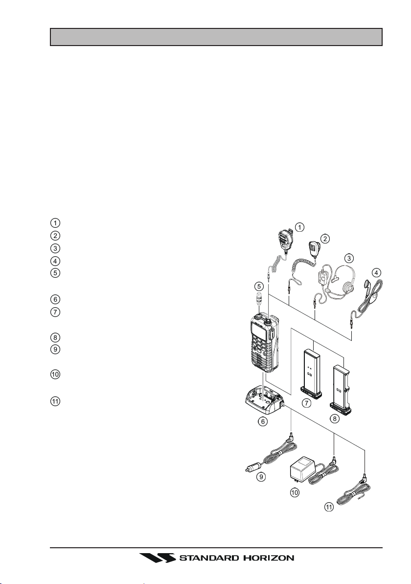
2.2 OPTIONS
MH-73A4B Speaker/Microphone
MH-57A4B Mini Speaker/Microphone
VC-24 VOX Headset
VC-27 Earpiece/Microphone
CN-3 Radio-to-Ship’s-Antenna
Adapter
CD-38 Charger Cradle
FNB-V99LI 7.4 V, 1150 mAh Li-Ion
Battery Pack
FBA-38 Alkaline Battery Case
E-DC-19A DC Cable with 12 V Ciga-
rette Lighter Plug
NC-88B/C/UÚWall Charger for the FNB-
V99LI
E-DC-6 DC Cable; plug and wire
only
Ú: “B” suffix is for use with 120 VAC (Type-A
plug), “C” suffix is for use with 230 VAC
(Type-C plug), and “U” suffix is for use with
230 VAC (Type-BF plug).
Note: Before operating the HX850S for the
first time, it is recommended that the battery
be charged. Please see section “4.1.5 US-
ING THE CD-38 CHARGER CRADLE” for details.
Page 9HX850S

3 ABOUT THIS RADIO
3.1 ABOUT THE VHF MARINE BAND
WARNING
The radio frequencies used in the VHF marine band lie between 156
and 158 MHz with NOAA Weather stations available between 161 and
163 MHz. The marine VHF band provides communications over distances that are essentially “Line of sight” Actual transmission range depends much more on antenna type, gain and height than on the power
output of the transmitter. On a fixed mount 25W radio transmission expected distances can be greater than 15 miles, for a portable radio transmission the expected distance can be greater than 5 miles in “Line of
sight”.
The user of a Marine VHF radio is subject to severe fines if the radio is
used on land. The reasoning for this is you may be near an inland waterway, or propagation anomalies may cause your transmission to be heard
in a waterway. If this occurs, depending upon the marine VHF channel
on which you are transmitting, you could interfere with a search and
rescue case, or contribute to a collision between passing ships. For
VHF Marine channel assignments refer to page 70 section 11.
HX850SPage 10

4 GETTING STARTED
4.1 RADIO CARE
CAUTION
Before following the instructions below, insure the speaker microphone
jack, antenna and battery are in place and firmly tightened. Care must
be taken if the radio was dropped and a close inspection may be needed
to insure the radio case and gaskets are in adequate condition.
Clean the radio with fresh water after exposure to salt water by rinsing the
radio under a sink faucet or by dunking the radio in a bucket of fresh water.
After washing, use a soft cloth and thoroughly dry all parts of the radio. This is
to keep the rubber switches and speaker grill clean and in top operating condition.
4.2 BATTERIES AND CHARGERS
If the radio has never been used, or its charge is depleted, it may be charged
by connecting the CD-38 Charger Cradle with the NC-88B battery charger, as
shown in the illustration. If 12V DC power is available, the optional E-DC-19A
DC Cable with 12 V Cigarette Lighter Plug or the optional E-DC-6 DC Cable
may be used for charging the battery. The NC-88B, E-DC-19A and E-DC-6 will
charge a completely discharged FNB-V99LI battery pack in about 8 hours.
The FNB-V99LI is a high performance Li-ion battery providing high capacity in
a compact package.
CAUTION
To avoid risk of explosion and injury, FNB-V99LI battery pack should
only be removed, charged or recharged in non-hazardous environments.
4.2.1 BATTERY SAFETY
Battery packs for your transceiver contain Li-ion batteries. This type of battery
stores a charge powerful enough to be dangerous if misused or abused, especially when removed from the transceiver. Please observe the following precautions:
DO NOT SHORT BATTERY PACK TERMINALS: Shorting the terminals that
power the transceiver can cause sparks, severe overheating, burns, and battery cell damage. If the short is of sufficient duration, it is possible to melt
battery components. Do not place a loose battery pack on or near metal surfaces or objects such as paper clips, keys, tools, etc. When the battery pack is
installed on the transceiver, the terminals that transfer current to the trans-
Page 11HX850S

ceiver are not exposed. The terminals that are exposed on the battery pack
when it is mounted on the transceiver are charging terminals only and do not
constitute a hazard.
DO NOT INCINERATE: Do not dispose of any battery in a fire or incinerator.
The heat of fire may cause battery cells to explode and/or release dangerous
gases.
Battery Maintenance
For safe and proper battery use, please observe the following:
y Battery packs should be charged only in non-hazardous environments;
y Use only STANDARD HORIZON-approved batteries;
y Use only a STANDARD HORIZON, (a Marine Division of VERTEX
STANDARD) approved charger. The use of any other charger may
cause permanent damage to the battery.
y Follow charging instructions provided with the chargers.
y Keep the battery contacts clean.
Battery Storage
Store the batteries in a cool place to maximize storage life. Since batteries are
subject to self-discharge, avoid high storage temperatures that cause large
self-discharge rates. After extended storage, a full recharge is recommended.
Battery Recycling
DO NOT PLACE USED BATTERIES IN YOUR REGULAR TRASH!
LI-ION BATTERIES MUST BE COLLECTED, RECYCLED OR DISPOSED
OF IN AN ENVIRONMENTALLY SOUND MANNER.
The incineration, land filling or mixing of Li-ion batteries with the municipal
solid waste stream is PROHIBITED BY LAW in most areas.
Return batteries to an approved Li-ion battery recycler. This may be where you
purchased the battery.
Contact your local waste management officials for other information regarding
the environmentally sound collection, recycling and disposal of Li-ion batteries.
HX850SPage 12
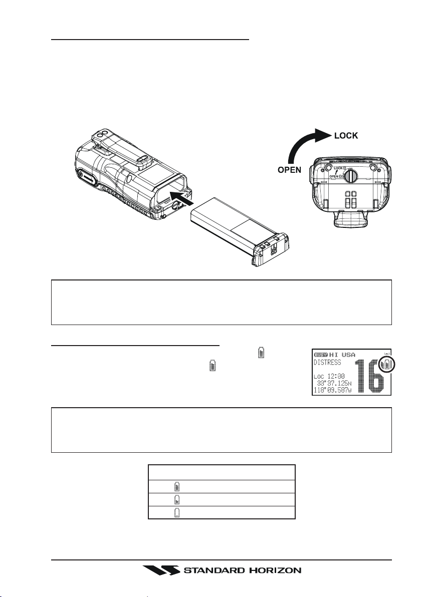
4.2.2 BATTERY INSTALLATION/REMOVAL
1. To install the battery pack, insert the battery pack into the bottom of the
transceiver, then turn the Battery Pack Lock on the bottom of the transceiver to the “LOCK” position with a coin.
2. To remove the battery pack, turn the transceiver off, turn the Battery Pack
Lock to the “OPEN” position with a coin, then slide out the battery from the
transceiver.
NOTE
The battery lock must be set to “LOCK” position to ensure water integrity and from the battery coming loose.
4.2.3 BATTERY LIFE INFORMATION
When the battery charge is almost depleted, a “ ” icon will
appear on the display. When the “ ” icon appears, it is
recommended that you charge the battery soon.
NOTE
When the FBA-38 Alkaline Battery Case is used, the battery icon does
not display correctly.
No Icon : Full Battery
: Low Battery
: Battery is very low
: Prepare to charge the Battery
Page 13HX850S
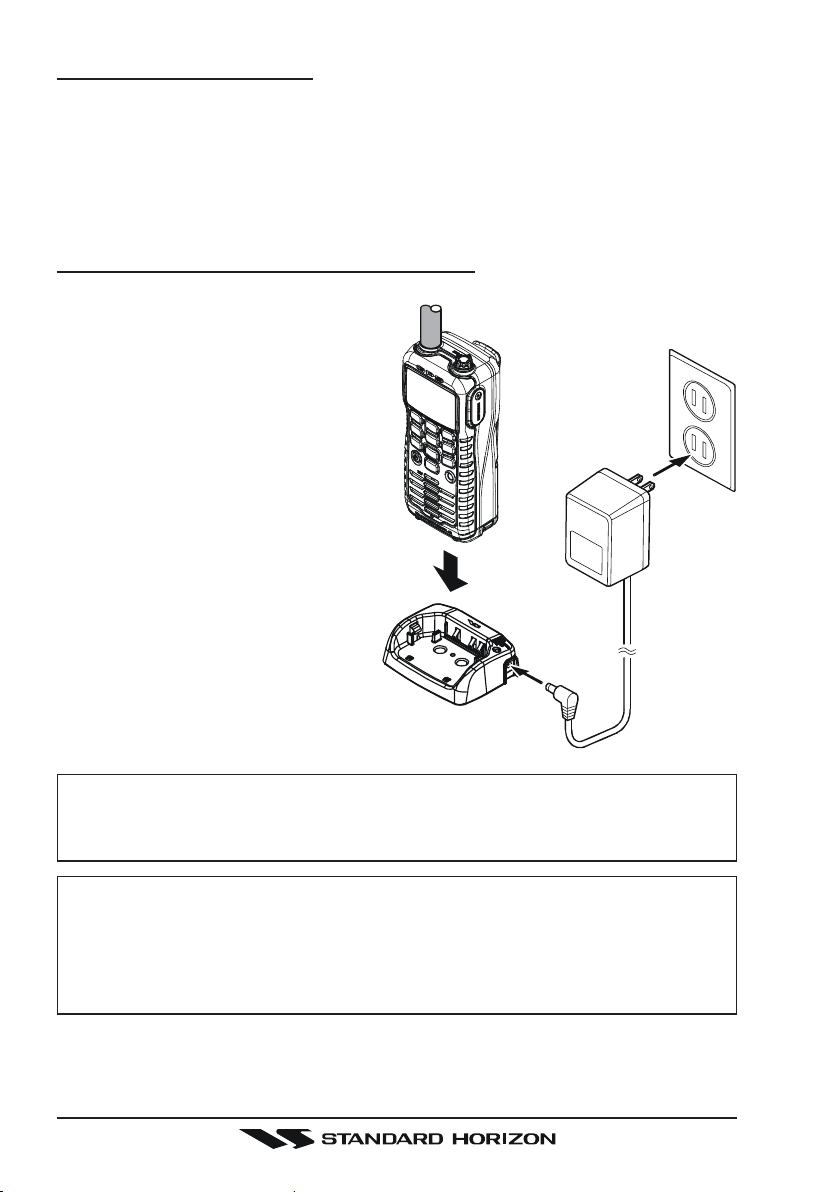
4.2.4 BATTERY CHARGING
If the radio has never been used, or its charge is depleted, it may be charged
by connecting the CD-38 Charger Cradle with the NC-88B battery charger, as
shown in the illustration. If 12V DC power is available, the optional E-DC-19A
DC Cable with 12 V Cigarette Lighter Plug or the optional E-DC-6 DC Cable
may be used for charging the battery. The NC-88B, E-DC-19A, and E-DC-6
will charge a completely discharged FNB-V99LI battery pack in about 8 hours.
4.2.5 USING THE CD-38 CHARGER CRADLE
1. Turn the transceiver off.
2. Insert the DC plug from the NC-
88B into the DC jack on the CD38 side panel, then plug the NC88B into the AC line outlet.
3. Insert the HX850S (with the battery pack) into the CD-38; the antenna should be at the left side
when viewing the charger from
the front.
4. If the HX850S is inserted correctly, the CD-38’s LED indicator will glow red. A fully-discharged pack will be charged
completely in approximately 8
hours.
5. When charging is completed, the
red LED indicator will change to
green.
CD-38
NC-88B
CAUTION
The CD-38 is NOT designed to be waterproof. Charge the radio in a dry
location.
NOTE
The CD-38 is only designed for the charging of the HX850S’s battery,
and is not suitable for other purposes. The CD-38 may contribute noise
to TV and radio reception in the immediate vicinity, so we do not recommend its use adjacent to such device.
HX850SPage 14
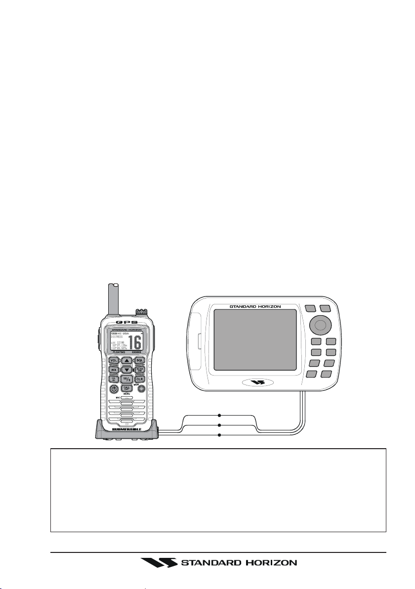
4.3 CONNECTING A CHART PLOTTER TO THE CD-38
The CD-38 contains three wires that are used to input or output NMEA information when the HX850S is inserted into the cradle.
The HX850S outputs the following sentences:
GLL, GGA, GSA, GSV, RMC, DSC and DSE.
The HX850S can receive and display information contained within the following NMEA sentences from and external GPS or GPS Chart Plotter:
GLL, GGA, and RMC.
Below are the wire colors and description of the wires supplied on the CD-38.
Brown: NMEA input
Blue: NMEA output
Green: NMEA Common
If you have further inquires, please feel free to contact Product Support at:
Phone: (800) 767-2450
Email: marinetech@vxstdusa.com
To connect a chart plotter, connect the wires between the CD-38 and the GPS
and chart plotter. Insure that the wires are properly shielded from water.
Brown Brown
Blue Blue
Green Green
NOTE
When mounting the HX850S inside of a cabin where GPS reception is
limited, the NMEA input (brown) wire may be connected to a GPS Chart
Plotter to input position into the HX850S. To change the HX850S from
using the internal GPS antenna to an external GPS chart plotter with
NMEA refer to section “9.8 POS DATA PRIORITY”.
Page 15HX850S
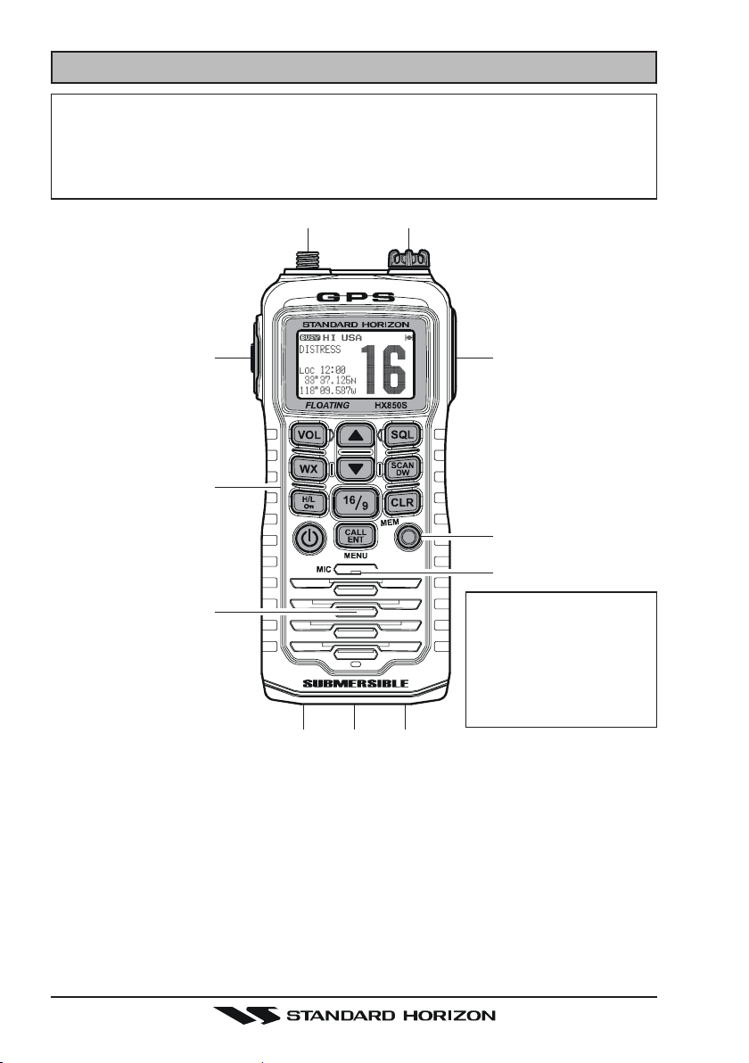
5 CONTROLS AND SWITCHES
NOTE
This section defines each control of the transceiver. For detailed operating
instructions, refer to section “6 BASIC OPERATION”. Refer to illustrations
for the location of the following controls, switches, and connections.
dc
f
g
h
i
j
When transmitting, position
your mouth about 1/2 to 1
inch (1.2 ~ 2.5 cm) away
from the small mic hole.
Speak slowly and clearly
into the microphone.
NOTE
kel k
ANT Jack (Top Panel
c
The supplied CAT460 flexible antenna is attached here.
MIC/SP Jack (Top Panel
d
The jack accepts the optional MH-73A4B Speaker/Microphone, MH-57A4B
Mini Speaker/Microphone, VC-24 VOX Headset, or VC-27 Earpiece/Microphone. When this jack is used, the internal speaker and microphone
are disabled.
PTT (Push-To-Talk) Switch (Left side
e
When pushed activates the transmitter.
)
)
)
HX850SPage 16

DISTRESS Key (Right side
f
This used to send a DSC Distress Call. To send the distress call, refer to
section “7.3.1 Transmitting a DSC Distress Alert”.
Keypad
g
[
VOL] Key
Press this key to activate the volume adjusting mode. Press the [T] or
[S]
key to adjust the receiver audio volume level.
[
SQL] Key
Press this key to activate the squelch adjusting mode. Press the [T] or
[S]
key to adjust the squelch threshold level.
Press and hold this key for 3 seconds to open the squelch, allowing
you to monitor the operating channel. Release the key to resume normal (quiet) monitoring.
)
[S(UP)]
[T(
[WX]
[
SCAN(DW)] Key
Key
This key is used to change the operating channel, receiver volume
level, and squelch threshold level.
Press the key momentarily, the channel (or level) increases one step.
Holding the key, the channel (or level) increases continuously.
DOWN) Key
This key is used to change the operating channel, receiver volume
level, and squelch threshold level.
Press the key momentarily, the channel (or level) decreases one step.
Holding the key, the channel (or level) decreases continuously.
Key
Immediately recalls the last-used NOAA Weather Channel from any
channel location. Recalls the previously- selected working channel when
the [WX] key is pressed again.
Secondary use:
When the [16/9] key is held and the [WX] key is pressed, the radio will
change the marine band between the USA, International, and Canadian channels.
Press this key to start scanning of programmed channels.
Secondary use:
Press and hold this key to watch for a transmission on CH16, another
selected channel, and CH70 until either signal is received (Triple Watch).
Page 17HX850S

[
( )]
H/L
[
16/9] Key
[
CLR(MEM)] Key
Key
Press this key to toggle the transmitter output power between “High”
(6 Watts), “M2” (5 Watts), “M1” (2.5 Watts), and “Low” (1 Watt) power.
This key does not function on the “Transmission Inhibited” and “Low
power only” channels.
Secondary use:
Hold down this key to lock the keypad (except the PTT, [VOL], [SQL],
[
POWER], and [H/L
changed. The “ ” icon will appear at the bottom right corner on the
display, to indicate that the functions are locked. Hold down this key
until the “ ” icon disappears to unlock the radio.
Pressing this key immediately recalls channel 16 from any channel
location. Holding down this key recalls channel 9. Pressing this key
again reverts to the previous selected working channel.
Press this key to cancel a menu selection and/or keypad entry.
Secondary use:
Press and hold this key to memorize the selected channel for scanning. When pressed a “MEM” icon will be shown on the LCD display
indicating the channel has been saved to scan memory. To delete the
channel from scan memory, select the channel and press and hold this
key until “MEM” is removed from the display.
Advanced use:
To enable the SOS Strobe light, turn off radio, press and hold this key
while turning on. To turn off strobe light, turn radio off and back on.
( )]
keys) so that they are not accidentally
[
POWER
[
CALL(ENT)MENU] KEY
( )]
KEY
Press and hold this key for two seconds to toggle the transceiver's
power on and off.
Press this key to access the DSC Call Menu. The “Individual Call”,
“Group Call”, “All Ships Call”, “Position Request”, “Position Report”,
“DSC Log”, and “DSC Test” functions can be accessed from the DSC
Call Menu.
Secondary use:
Press and hold this key to access the “Radio Setup”, “DSC Setup” or
“GPS Setup” menu.
HX850SPage 18
TX/BUSY Indicator
h
This indicator glows green when a signal is being received and red when
transmitting.
When the Emergency feature is activated, this indicator blinks the internationally-recognized Morse Code “S.O.S” message.
Microphone
i
The internal microphone is located here.
NOTE
When transmitting, position your mouth about 1/2 to 1 inch (1.2 ~
2.5 cm) away from the small mic hole. Speak slowly and clearly into
the microphone.
Speaker
j
The internal speaker is located here.
NMEA Terminals (Bottom side
k
Connect this NMEA input/output terminal to the GPS or Chart Plotter via
the CD-38 Charger Cradle. Keep these terminals clean.
Battery Pack Lock (Bottom side
l
Turn the Battery Pack Lock to the “OPEN” position for battery removal.
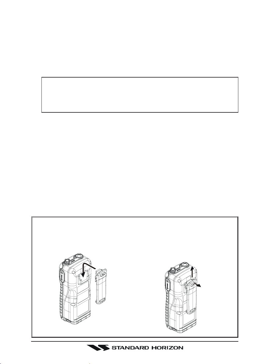
BELT CLIP INSTALLATION / REMOVAL
INSTALLATION
Install the Belt Clip as shown
below.
)
)
REMOVAL
Pulling the Belt Clip toward up
(d)
while pulling the top edge of
the Belt Clip toward back
(c)
d
c
.
Page 19HX850S

6 BASIC OPERATION
6.1 PROHIBITED COMMUNICATIONS
The FCC prohibits the following communications:
y False distress or emergency messages:
y Messages to “any boat” except in emergencies and radio tests;
y Messages to or from a vessel on land;
y Transmission while on land;
y Obscene, indecent, or profound language (potential fine of $10,000).
6.2 INITIAL SETUP
1. Install the battery pack on the transceiver (see section “4.2.2 BATTERY
INSTALLATION/REMOVAL”).
2. Install the antenna onto the transceiver; hold the bottom end of the antenna, then screw it onto the mating connector on the transceiver until it is
snug. Do not over-tighten.
NOTE
Water resistance of the transceiver is assured only when the battery
pack is attached to the transceiver and MIC/SP cap is installed in the
MIC/SP jack.
6.3 RECEPTION
1. Press and hold the [POWER
ceiver on.
2. Press the [SQL] key to activate the squelch adjusting mode. Press the [T
key until the “ ” indicator will appear on the display, then press the
[
SQL] key again (or wait 3 seconds to exit from the squelch adjusting mode).
3. Press the [VOL] key to activate the audio volume adjusting mode. Press
the [T] / [S] key until the noise or audio from the speaker is at a comfortable level, then press the [VOL] key again (or wait 3 seconds to exit from
the audio volume adjusting mode).
4. Press the [SQL] key to activate the squelch adjusting mode again. Press
the [S] key until the random noise disappears, then press the [SQL] key
again (or wait 3 seconds to exit from the squelch adjusting mode). This
state is known as the “Squelch Threshold”.
5. Press the [T] or [S] key to select the desired channel. Refer to the channel chart on page 71 for available channels.
6. When a signal is received, adjust the volume (Press the [VOL] key, followed by the [T]/[S] key) to desired listening level. The “ ” indicator
will appear on the display indicating that the channel is being used.
( )]
key for two seconds to turn the trans-
]
HX850SPage 20
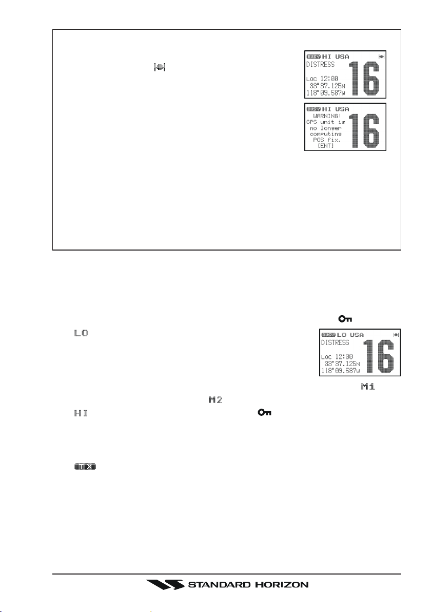
NOTE
When the transceiver succeeds in the reception of
the GPS signal, a “ ” icon will appears on the upper right corner and current time appears on the
lower left corner with the Position time on the display. When the transceiver fails in the reception of
the GPS signal, the radio will show the display on
the right. In this case, you may be in a poor location
for satellite reception, such as indoor use; try moving to a less obstructed position.
When the HX850S is first turned on, it may take several minutes to
compute a fix of your position. This is normal, as the HX850S is downloading “almanac” information from the GPS satellites.
To display your position (Log/Lat) on the display, refer to section “6.5
DISPLAYING THE GPS RECEIVING DATA”.
6.4 TRANSMISSION
1. Perform the “6.3 RECEPTION” discussion above.
2. Before transmitting, monitor the channel and make sure it is clear.
THIS IS AN FCC REQUIREMENT!
3. For communications over short distances, press the [H/L
“ ” is displayed on the display. This indicates Low
power (approximately 1 watt).
Note: Transmitting on 1 watt prolongs battery life. Low
power (1 watt) should be selected whenever possible.
4. If using Low power is not effective, select M1 power (2.5 watts: “ ” icon
appears), M2 power (5 watts: “ ” icon appears), or High power (6 watts:
“ ” icon appears) by pressing the [H/L
5. When receiving a signal, wait until the incoming signal stops before transmitting. The transceiver cannot transmit and receive simultaneously.
6. Press the PTT (Push-To-Talk) switch to transmit. During transmission, the
“ ” indicator will appear on the display and the TX/BUSY indicator will
grow red.
7. Position your mouth about 1/2 to 1 inch (1.2 ~ 2.5 cm) away from the small
mic hole. Speak slowly and clearly into the microphone.
8. When the transmission is finished, release the PTT switch.
( )]
key.
( )]
key until
Page 21HX850S

6.4.1 TRANSMIT TIME - OUT TIMER (TOT
While the PTT switch is held down, transmission time is limited to 5 minutes.
This prevents prolonged (unintentional) transmissions. About 10 seconds before automatic transmitter shutdown, a warning beep sounds from the speaker.
The transceiver automatically switches to the receiving mode, even if the PTT
switch is held down. Before transmitting again, the PTT switch must first be
released, then wait 10 seconds and pressed again. This Time-Out-Timer (TOT)
prevents a continuous transmission that would result from an accidentally stuck
PTT switch.
NOTE
The PTT switch is ignored for 10 seconds after the transceiver automatically switches to the receiving mode by the TOT feature.
)
6.5 DISPLAYING THE GPS RECEIVING DATA
The HX850S will display your position (Longitude/Latitude) using the internal
GPS receiver. To display your position on the display:
1. Press and hold the [CALL(ENT)MENU] key until the
Setup MenuSetup Menu
“
Setup Menu” appears.
Setup MenuSetup Menu
2. Select “
the [CALL(ENT)MENU] key.
3. Select “
[
CALL(ENT)MENU] key.
4. Select the desired Display Type with the [T] / [S] key.
RadioRadio
Radio: Displays the “ ” icon only.
RadioRadio
PositionPosition
Position: Displays your position and current time
PositionPosition
NavigationNavigation
Navigation: Displays your position, COG (Course
NavigationNavigation
GPS StatusGPS Status
GPS Status: Displays apparent reception of GPS satellites, including the
GPS StatusGPS Status
5. Press the [CALL(ENT)MENU] key to store the selected setting, and return
to radio operation mode.
Radio SetupRadio Setup
Radio Setup” with the [T] / [S] key, then press
Radio SetupRadio Setup
DisplayDisplay
Display” with the [T] / [S] key, then press the
DisplayDisplay
on the display.
Over Ground: your current direction), and
current time on the display
bar-graph of signal strengths.
“RADIO” MODE “POSITION” MODE “NAVIGATION” MODE “GPS STATUS” MODE
HX850SPage 22
NOTE
When the “GPS Status” mode is selected in step “4” above, the display
keeps the “
When “
DSC signal when the radio acquires a GPS fix.
You may customize the various functions of the HX850S internal GPS unit for
your operating requirements via the “GPS Setup” menu. Refer to section
“9 GPS SETUP” for details.
GPS StatusGPS Status
GPS Status” page until a key is pressed.
GPS StatusGPS Status
NOTE
RadioRadio
Radio” mode is selected, the HX850S will add position data to a
RadioRadio
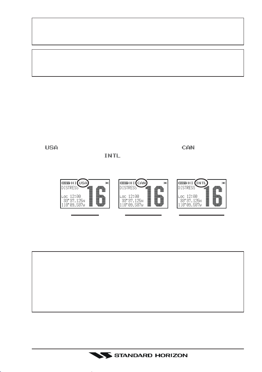
6.6 USA, CANADIAN, AND INTERNATIONAL CHANNELS
1. To change from US to Canadian or International Marine Channels, hold
down the [16/9] key and press the [WX] key. The band will change from
USA, to International, and to Canadian with each press.
2. “ ” appears on the LCD for the USA band, “ ” appears for the
Canadian band, and “ ” appears for the International band.
3. Refer to the marine channel charts in section “11 CHANNEL ASSIGN-
MENTS” for allocated channels.
“USA” BAND “CANADIAN ” BAND “INTERNATIONAL” BAND
6.7 SIMPLEX/DUPLEX CHANNEL USE
Refer to the VHF MARINE CHANNEL CHART (page 71) for instructions on
use of simplex and duplex channels.
NOTE
All channels are factory-programmed in accordance with FCC (USA),
Industry Canada and International regulations. The mode of operation
cannot be altered from simplex to duplex or vice-versa. Simplex (ship to
ship) or duplex (marine operator) mode is automatically activated, depending on the channel and whether the USA, International or Canadian operating band is selected.
Page 23HX850S

6.8 NOAA WEATHER CHANNELS
1. To receive a NOAA (National Oceanic and Atmospheric
Administration) weather broadcast, press the [WX] key.
The transceiver changes to the weather channel mode.
This mode consists of a preset memory bank containing the NOAA weather channels.
2. When the [WX] key is pressed, the transceiver will be set to the last used
NOAA weather channel. Press the [T] or [S] key to change to other weather
channels.
3. To exit from the weather channel mode, press the [WX] key. The transceiver will revert to the channel you were using prior to switching to the
weather channel mode.
6.8.1 NOAA WEATHER ALERT
In the event of extreme weather disturbances such as storms and hurricanes,
NOAA sends a “weather alert” consisting of a 1050 Hz tone, followed by weather
reports on the weather channels.
When a “weather alert” is received on a weather channel, the transceiver emits
a beep tone. Press the [WX] key to stop the beep tone and listen to the weather
reports.
NOTE
Four options for the Weather Alert feature are available, refer to section
“8.9 WEATHER ALERT” for details.
6.8.2 NOAA WEATHER ALERT TESTING
In the event of a major storm or other appreciable weather condition requiring
vessels at sea (or other bodies of water) to be notified, the NOAA (National
Oceanographic and Atmospheric Administration) broadcasts a 1050 Hz tone
that some VHF radios, including your HX850S, can detect for “Weather Alarm”
purposes (refer to section “6.8.1 NOAA WEATHER ALERT” for a discussion
of how to use this feature). The 1050 Hz tone, when detected, will produce a
loud beep in the speaker of the HX850S, to signal that a Weather Alert Broadcast is being received.
In order to test this system, NOAA broadcasts the 1050 Hz tone every Wednesday sometime between 11 AM and 1 PM local time. You may use this opportunity to test your HX850S periodically to confirm that the Weather Alert feature
is working, or for training crew members on how to configure the HX850S to
receive the NOAA Weather Alerts.
HX850SPage 24
6.9 SCANNING
The HX850S allows the user to select the scan type from “memory Scan” or
“Priority Scan”. The “Memory Scan” scans the channels that were programmed
into memory. The “Priority Scan” scans the channels programmed in memory
with the user selected priority channel.
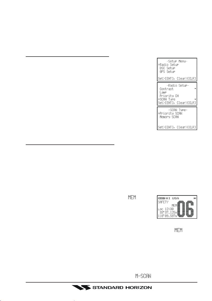
6.9.1 SELECTING THE SCAN TYPE
1. Press and hold the [CALL(ENT)MENU] key until the
Setup MenuSetup Menu
“
Setup Menu” appears.
Setup MenuSetup Menu
2. Select “
the [CALL(ENT)MENU] key.
3. Select “
the [CALL(ENT)MENU] key.
4. Select the desired Scan Type (“
ority Scanority Scan
ority Scan”) with the [T] / [S] key.
ority Scanority Scan
5. Press the [CALL(ENT)MENU] key to store the selected
setting.
6. Press the [16/9] key to exit the “
return to radio operation mode.
Radio SetupRadio Setup
Radio Setup” with the [T] / [S] key, then press
Radio SetupRadio Setup
SCAN TypeSCAN Type
SCAN Type” with the [T] / [S] key, then press
SCAN TypeSCAN Type
Memory ScanMemory Scan
Memory Scan” or “
Memory ScanMemory Scan
Radio SetupRadio Setup
Radio Setup” menu and
Radio SetupRadio Setup
Pri-Pri-
Pri-
Pri-Pri-
6.9.2 MEMORY SCANNING (M-SCAN
The “Memory Scan” scans the channels that were programmed into memory.
The HX850S can be programmed to scan channels from a minimum of 2 channels up to all channels in the marine band. If an incoming signal is detected on
one of the channels during scan, the radio will pause on that channel, allowing
you to listen to the incoming transmission.
1. Select the desired channel to be included in the scan memory using the
[T]
or [S] key.
2. Press and hold the [CLR(MEM)] key until “ ” icon is
shown on the display, thus the current channel is stored
into the transceiver’s scan memory.
3. Repeat steps 1 and 2 for all the channels to be scanned.
4. To delete a channel from the transceiver’s scan memory, select the memorized channel, then press and hold the [CLR(MEM)] key until “ ” is removed from the display.
5. All channels programmed remain in the transceiver’s scan memory even if
the power is turned off.
6. To start scanning, press the [SCAN(DW)] key. The scan proceeds from the
lowest to the highest programmed channel and stops scanning when a
transmission is received. Scanning will resume when the incoming signal
disappears at the end of the transmission. A “ ” icon will appears at
)
Page 25HX850S
the upper left of the display during scanning.
7. To stop the scan, press the [SCAN(DW)] key or
[
CLR(MEM)] key.
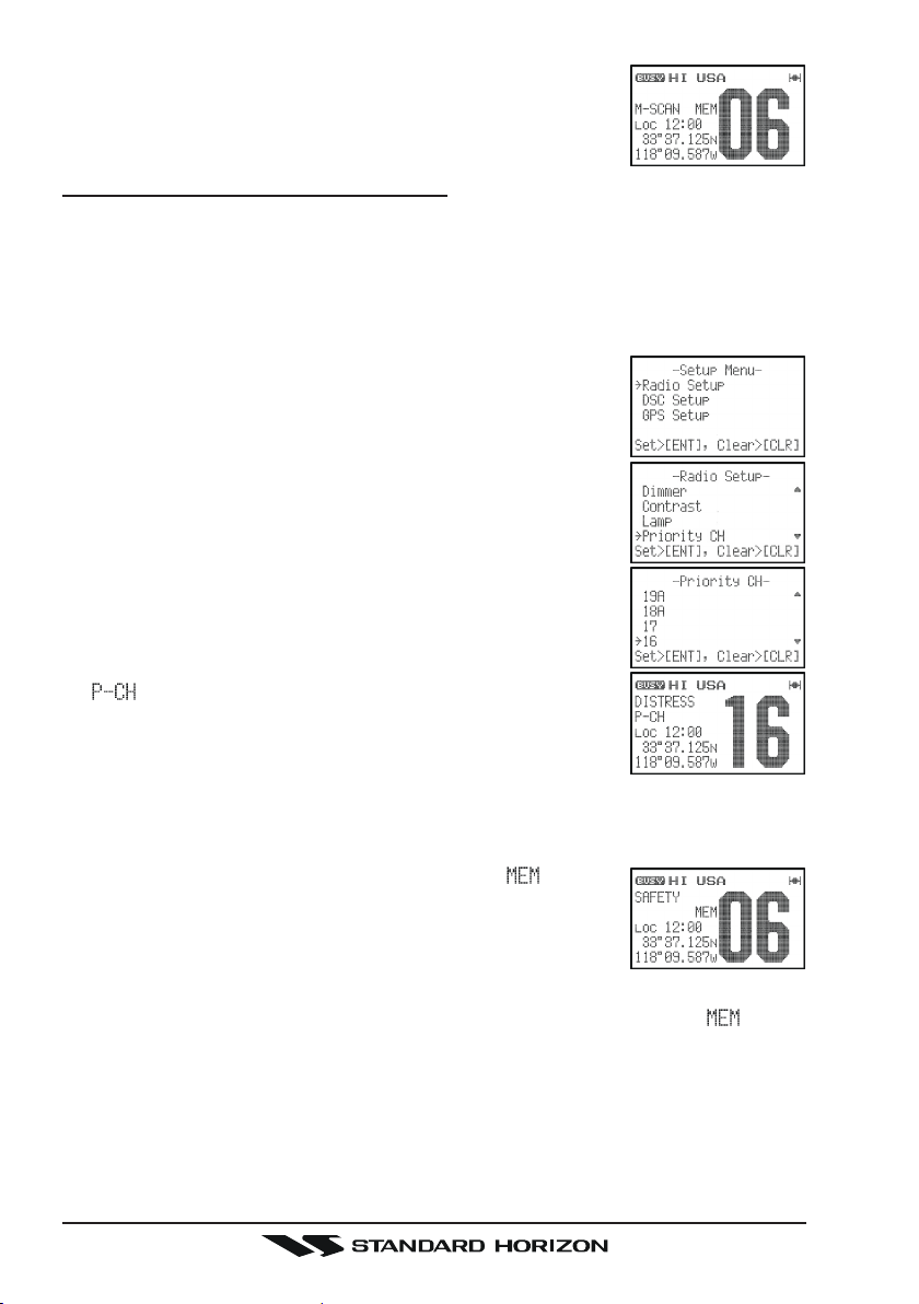
6.9.3 PRIORITY SCANNING (P-SCAN
The “Priority Scan” allows the radio to “Memory Scan” while also keeping watch
on a particularly important “Priority Channel”. In the default setting, Channel
16 is set as the priority channel. You may change the priority channel to the
desire channel from the Channel 16 by the “Radio Setup” menu.
Setting Up the Priority Channel
1. Press and hold the [CALL(ENT)MENU] key until the
Setup MenuSetup Menu
“
Setup Menu” appears.
Setup MenuSetup Menu
2. Select “
the [CALL(ENT)MENU] key.
3. Select “
the [CALL(ENT)MENU] key.
4. Select the desired channel to be a priority with the [T
/ [S] key, then press the [CALL(ENT)MENU] key to
store the selected setting.
5. Press the [16/9] key to exit the “
return to radio operation mode.
A “ ” icon will appears at the upper left of the display
when the priority channel is recalled.
Operation
1. Select the desired channel to be included in the scan memory using the
[T]
2. Press and hold the [CLR(MEM)] key until “ ” icon is
shown on the display, thus the current channel is stored
into the transceiver’s scan memory.
3. Repeat steps 1 and 2 for all the channels to be scanned.
4. To delete a channel from the transceiver’s scan memory, select the memorized channel, then press and hold the [CLR(MEM)] key until “ ” is removed from the display.
5. All channels programmed remain in the transceiver's scan memory even if
the power is turned off.
6. To start priority scanning, press the [SCAN(DW)] key. The scan proceeds
from the lowest to the highest programmed channel and stops scanning
when a transmission is received. Scanning will resume when the incoming
Radio SetupRadio Setup
Radio Setup” with the [T] / [S] key, then press
Radio SetupRadio Setup
Priority CHPriority CH
Priority CH” with the [T] / [S] key, then press
Priority CHPriority CH
or [S] key.
)
Radio SetupRadio Setup
Radio Setup” menu and
Radio SetupRadio Setup
]
HX850SPage 26
 Loading...