

Page 1
Standard 2 Inch Installation
Dual Station Operation
NMEA Repeater
Reads in Feet Fathoms or Meters
Adjustable Prop or Surface Offset
Shallow and Deep alarms
DS41
Digital Depth Sounder
Owner’s Manual
Dual
Station
Operation
Page 2

Contents
Specifications .................................................................................................................2
Operation ........................................................................................................................3
Alarms ........................................................................................................................ 3
Alarms On/Off .............................................................................................................3
Shallow Alarm ............................................................................................................ 3
Deep Alarm ................................................................................................................ 4
Instrument Setup............................................................................................................4
Keel/Surface Offset ....................................................................................................4
Transducer Setting ..................................................................................................... 5
Units of Measure ........................................................................................................5
Troubleshooting..............................................................................................................6
What comes with your Digital Depth Sounder .............................................................7
Standard ....................................................................................................................7
Options .......................................................................................................................7
Replacement Parts .................................................................................................... 8
Installation ......................................................................................................................9
Face Plate Installation ................................................................................................9
Instrument Installation ................................................................................................ 9
Transducer Installation .............................................................................................1 1
General...............................................................................................................11
Sailboats ............................................................................................................12
Powerboats.........................................................................................................12
Transom Installation ........................................................................................... 1 3
In-Hull Installation .............................................................................................. 13
Appendix A – Dual Station Operation .........................................................................14
Master/Slave Selection ............................................................................................ 14
Linked or Separate Selection ..................................................................................1 5
Appendix B – NMEA Repeater Mode..........................................................................16
DS41/HS/2G
DS41 Owner’s ManualDS41 Owner’s Manual
Page 3

Specifications
• Size
Mount 2" (51mm) diameter hole
Depth behind face plate 3.75" (95mm) max.
Display 3-character LCD
• Color
Black with texture on bezel.
• Backlighting
Red colored diffused lighting for display.
• Water Integrity
Front will withstand direct water spray.
• Depth/Alarm Range
2.0!600 feet
0.6!184 meters
0.3!100 fathoms
(to 9.9 in tenths)
• Sensitivity
0.05mV RMS.
• Transmit Power
36 W RMS nominal at 13.6 VDC.
• Transducer
200 kHz 1900 pF/600 W parallel.
• Display Updating
1 second.
• Operating Voltage
9.5 VDC to 16.5 VDC.
• Operating T emperature
0°C to 50°C (32°F to 122°F).
• Current Drain
150mA max, including internal buzzer.
• Data Input/Output
Single wire data output/Input.
Dual station mode outputs NMEA DPT
sentence. Dual station inputs NMEA DPT
sentence. In the linked mode a dual station
pair also transfer function settings eg. Alarm
on/off.
• NMEA Output
DPT.
• NMEA Input
DPT and DBT.
• External Buzzer Output
12VDC Buzzer, 100 mA max.
• RF Interference
<6 dB quieting on any marine radio channel
(with 3 dB gain antenna) within one meter of
the instrument. Complies with CE EMC
standards EN50081-1 and EN50082-1.
Display is backlit for
Night Operation
Alarm On/
Change Value Up
DS41 Owner’s Manual2
888
Horizon Depth
^
OFFON
V
Change Value Down
Alarm Off/
Page 4
Operation
OFF
ON
^
V
OFFON
V
OFFONON
^^
V
8
OFFOFFONON
^^
VV
Whenever power is applied the depth sounder
is active and water depth is displayed. If the
sonar signal does not show a bottom the display
will indicate “- -”. This can occur if the water is
aerated or the maximum depth is exceeded.
Note: The maximum depth decreases as boat
speed increases.
Alarms
Two types of alarms can be set; the Deep Alarm
and the Shallow Alarm. The Deep Alarm can be
set as high as 184 meters (605 feet) while the
Shallow Alarm can be set as low as 0.3 meter
(1 foot).
Whenever the water depth is greater than the
Deep Alarm setting and the alarm is enabled an
alarm will sound. The alarm repeats two shor t
beeps and alternates DAL and the water depth
on the display.
Whenever the water depth is less than the
Shallow Alarm setting and the alarm is enabled
an alarm will sound. The alarm repeats a single
long beep and alternates SAL and the water
depth on the display.
Alarms On/Off
Alarm settings are saved in memory.
To turn the alarm on, press the " (ON) key. An
arrow on the lower right corner of the display will
show (next to the Alarm Bell), to indicate that the
alarms are on.
Note:
The arrow will flash if alarms are turned
ON but the shallow alarm is individually
set to OFF. See next section.
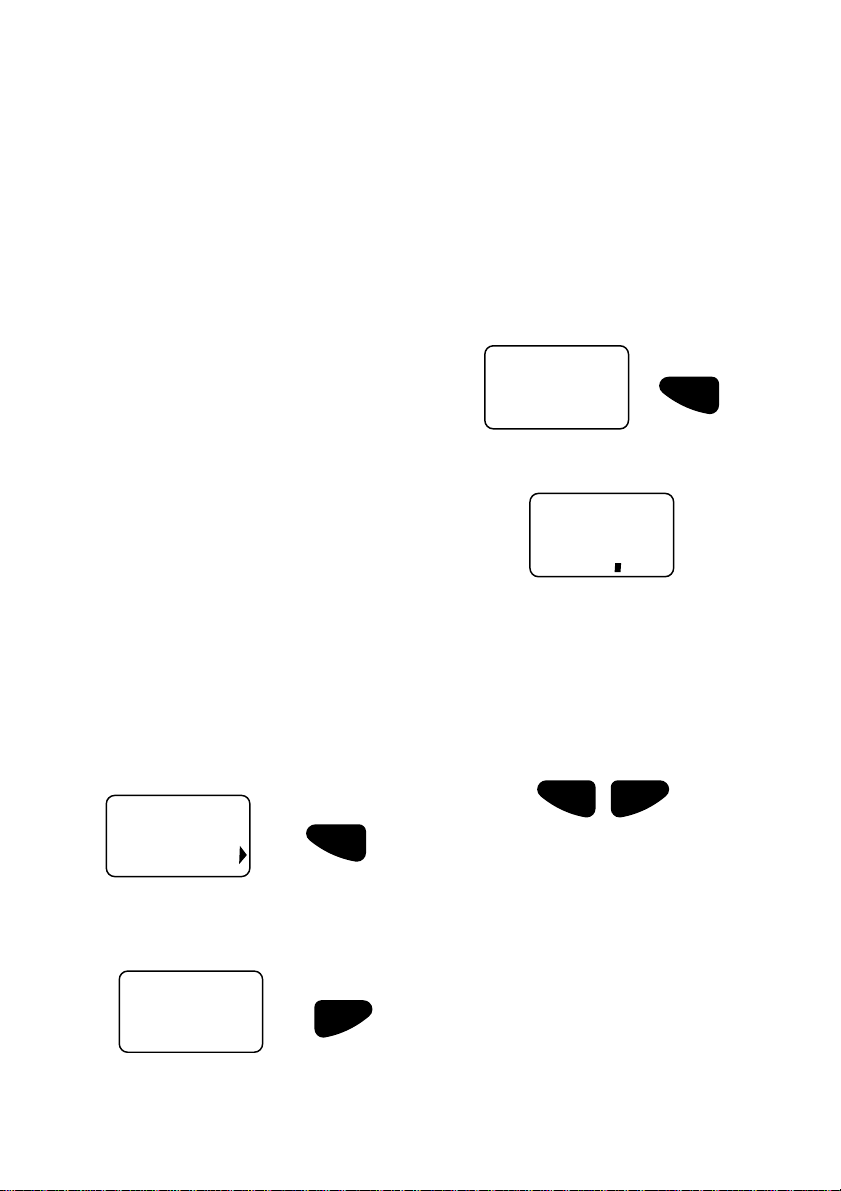
Shallow Alarm
To set the shallow alarm:
1. Press the " key for three seconds. The
display will show:
Press for 3 Seconds
SAL
2. After a few seconds the display will indicate
the current Shallow Alarm depth setting.
8
51
3. Use the " and # keys to change the
value. If either key is held depressed for
more than one second the reading will
increase or decrease rapidly.
4. When the alarm is set, exit by pressing
both the " and # keys simultaneously.
Alternatively, if no keys are pressed for a
period of 5 seconds the normal depth
display will resume.
ON
^
V
OFF
120
To turn the alarms off, press the # (OFF) key.
The arrow in the lower right corner will
extinguish.
120
#
#
Press simultaneously to exit
If the reading is decreased to below
1.5 feet (or equivalent) the display will
show
!""
and the alarm will be disabled.
The alarm can also be disabled by
pressing both the " and # keys for 5
seconds. The word
but the alarm depth will be retained for
Note:
!""
will be displayed
future use.
DS41 Owner’s Manual3
Page 5
OFFON
V
8
OFF
ON
^
V
Instrument Setup
OFF
ON
^
V
Deep Alarm
To set the deep alarm:
1. Press the # key for three seconds. The
display will show:
OFF
V
dAL
2. After two seconds the display will indicate
the current Deep Alarm depth setting.
8
50
3. Use the " and # keys to change the
value. If either key is held depressed for
more than one second the reading will
increase or decrease rapidly.
4. When the alarm is set, exit by pressing
both the " and # keys simultaneously.
Alternatively, if no keys are pressed for a
period of 5 seconds the normal depth
display will resume.
ON
^
Press simultaneously to exit
3 Seconds
OFF
V
Press for
Keel/Surface Offset
An offset may be automatically added to or
subtracted from the depth reading to
compensate for the location of the transducer.
This allows the instrument to indicate the water
depth relative to the bottom of the keel or the
surface of the water.
To set the keel/surface offset:
1. Apply power while holding down the " key.
ON
^
Hold down during power up
2. When the unit is on, release the " key. The
display will indicate if the current offset is
keel offset or waterline offset:
Hull Offset (Depth below the keel)
If the reading is increased one step above
600 feet (or equivalent) the display will
show
!""
and the alarm will be disabled.
The alarm can also be disabled by
pressing both the " and
seconds. The word
but the alarm depth will be retained for
DS41 Owner’s Manual4
Note:
!""
will be displayed
future use.
#
keys for 5
Surface Offset (Depth below the surface)
3. After 5 seconds the display will indicate the
current offset.
Note:
A negative offset is used to display depth
below the keel and a positive offset is
used to display depth below the surface.
Page 6

4. Use the " and # keys to change the
OFF
ON
^
V
OFFON
V
88Ft
8888
88FA
OFFOFFONON
^^
VV
tdr
value. If either key is held depressed for
more than one second the reading will
increase or decrease rapidly.
5. The offset can be programmed in 0.1 unit
steps from -9.9!9.9 feet (or equivalent).
When programmed for a negative offset, ‘-’
will be indicated on the left hand side of the
display.
6. To display depth below the keel enter the
vertical distance between the bottom of the
keel and the depth trasnducer as a
negative value.
7. To display depth below surface enter the
vertical distance from the waterline to the
depth transducer as a positive number (no
negative sign).
8. To exit this mode, press and hold both the
" and # keys simultaneously. Alternatively,
if no keys are pressed for a period of 5
seconds normal depth display will resume.
The display will now indicate the current
water depth.
T ransducer Setting
A Transducer Setting is provided to allow the
D41 to be used with different transducer types.
The default setting (=0.0) is used for most
transducers.
Some transducers ‘ring’ after the sonar transmit
pulse (just like hitting a bell). This ringing can be
interpreted as an echo from a shallow bottom.
The setting is used to increase the required level
that shallow echoes must meet before they will
be displayed.
If the D41 gives repeated false readings of 1.5
to 3 feet depth while in deep water the transducer
setting should be increased. Adjust it upward by
0.5 at a time and retest. The range of values is
-0.9 to +2.5. If the value is set too high it could
cause erratic readings in shallow water.
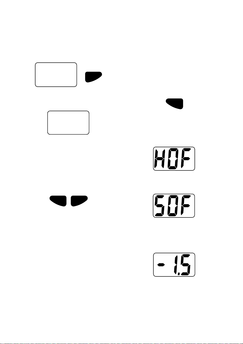
Changing the Transducer Setting
1. Apply power while holding down the "ON
key. The display will show either HOF or
SOF for 7 seconds. Continue to hold the
key down.
ON
^
Press simultaneously
V
OFF
2. The display will show tdr.
3. Release the key.
4. After 2 seconds the display will show the
Transducer Setting value eg 0.0
5. Use the " and # keys to change the
value.
6. To exit this mode, press and hold both the
" and # keys simultaneously.
Units of Measure
To select the displayed unit
1. Apply power while holding down the # key.
OFF
V
Hold down during power up
2. When the unit is on, release the # key. The
display will indicate the current display unit
with:
Feet Meters
Fathoms
3. Use the " and # keys to change the
value.
4. To exit this mode, press and hold both the
" and # keys simultaneously. Alternatively,
if no keys are pressed for a period of 5
seconds normal depth display will resume.
Press simultaneously
The display will now indicate the current
water depth in the selected display unit.
DS41 Owner’s Manual5
Page 7

Troubleshooting
No display:
1. Check DC power connections and DC polarity with voltmeter.
2. Check fuse.
No depth reading (
Erratic readings while moored:
Erratic readings while moving:
Erratic readings only while engine is running:
####
##) at all depths:
####
1. Check transducer for growth or multiple coats of paint.
2. Check the transducer cable for cuts and sharp bends.
3. Check that the transducer connection behind the D41is firm and free of
corrosion.
Check transducer for growth or multiple coats of paint.
Cavitation (air) under the face of the transducer. Review installation and
reinstall if necessary.
1. Re-route power and transducer cables away from engine, ignition wires
and battery cables.
2. Add feed-through filter capacitor on the positive terminal of the ignition
coil.
3. Add an alternator whine filter to alternator.
4. Replace spark plug wire with resistive type.
DS41 Owner’s Manual6
Page 8

What comes with your Digital Depth Sounder
Standard
Mounting Bracket ................................................................. With mounting hardware
Extension Power Cord ......................... 6 feet long with quick-disconnect connectors
Twist Lock Face Plate........................................................................................Round
Options
Plastic Low Profile Transducer
DTS50
Bronze Long Stem Thru-hull Transducer
Transom Mount Transducer
DTS51
DTS52
DS41 Owner’s Manual7
Page 9

13°
2.75"
2.125"
Bronze Low Profile Transducer
DTS53
Note: All transducers come with 30 feet of cable.
DTS55
In-Hull Transducer
Replacement Parts
The following parts may be ordered from the Parts Depar tment. To order, call Toll-free
Number: 1-800-487-2788.
Square Face Plate ............................................................ Part Number 568001012A
Round Face Plate ............................................................. Part Number 568002012A
Gasket ............................................................................. Part Number RRDS410001
Mounting Bracket .............................................................. Part Number 160001020A
Mounting Nut ..................................................................... Part Number 580010123A
DS41 Owner’s Manual8
Page 10

Installation
Face Plate Installation
1. To install a face plate:
a) Attach the face plate to the front panel
of the instrument.
b) Twist the face plate clockwise until tight.
2. To remove face plate, twist it anticlockwise
until loose and detach.
Instrument Installation
The instrument can be easily installed in different
types of instrument panels. Refer to Figures 3,
4, and 5 for the following steps.
1. Select a suitable location for the instrument.
When selecting the location for mounting,
the following are recommended:
• Controls of the instrument must be
accessible to the user.
• Electrical connections must be routed to
the boat system as directly as possible,
minimising the length of cable where
practical.
• Location should provide as much
protection from the elements as
possible.
• The panel for mounting the instrument
should be 1/8 to 3/4 inch thick.
• The space behind the instrument panel
must have a depth of at least 3.75
inches. See Figure 1 for dimensions of
the instrument.
2. Drill a 2-inch hole on the instrument panel
in the selected location.
3. With the mounting bracket removed, insert
the instrument into the hole until the back of
the face plate is flush with the outside
mounting wall.
4. Slide the bracket over the body of the
instrument.
Note:
Orient the bracket in such a manner
that it does not cover the buzzer.
5. Tighten the mounting nut until the bracket
is secure.
.75"
2.5"
2.5"
INTERCHANGEABLE FACE PLATES
SQUARE FACE PLATEROUND FACE PLATE
2.5"
3.75".5"
Figure 1. Depth Sounder Dimensions
DS41 Owner’s Manual9
Page 11

6. Connect the power cord at the back of the
instrument to a 12 V power supply which is
active whenever the ignition switch is on.
The red lead should be connected to the
positive terminal of the power supply via a
1 amp fuse or a 1 amp circuit breaker. The
black lead should be connected to the
negative terminal.
Instrument
Panel
7. Obtain the power from a 12 V source as
directly as possible. Avoid power circuits
which share loads with ignition, alternators,
radio transmitters, etc. Excessive electrical
noise associated with such devices may
prevent the instrument from operating
properly.
8. Connect the RCA phono plug on the
transducer cable to the instrument.
FACE PLATE
2-Inch
Hole
Mounting
Instrument
Sealing
Gasket
Figure 2. Depth Sounder Installation
INSTRUMENT
PANEL WALL
Bracket
MOUNTING
NUT
Mounting Nut
MOUNTING
BRACKET
DEPTH SOUNDER
BODY
Figure 3. Side View of Mounted Depth Sounder
DS41 Owner’s Manual10
Page 12

T ransducer Installation
Note:
The installation of a transducer is a job
for a professional boat yard that performs
numerous installations.
The following is an informational guide-
line on the installation of transducers.
General
Correct installation of the transducer is essential
for optimum operation of the instrument. Select
a location for the transducer using the following
guidelines:
• Non-aerated water (bubble-free) water
must flow across the face of the
transducer at all speeds if good depth
performance is to be achieved.
• Never position the transducer directly
behind shafts, struts, fittings and
paddlewheel speed transducers because
water turbulence underneath the
transducer face can adversely affect depth
performance.
• Keep the transducer cable away from the
engine to reduce electrical interference.
• If the boat has bottom paint applied and
has been used, inspect for areas where
paint erosion has taken place. Erosion is
caused by turbulent water and these areas
are unsuitable transducer mounting
locations.
• It is very important that the mounting
location have reasonable access from
inside the vessel since the transducer will
require tightening from inside the hull.
• Plastic thru-hull transducers should be
mounted in fiberglass and metal hulls only.
Under no circumstances should they be
used in wood hulls. Swelling of the wood
may overstress the plastic housing.
• Do not use a fairing block of any type when
mounting the plastic low profile transducer.
Hauling or impact can cause structural
failure of the housing assembly.
• Do not expose a plastic thru-hull transducer
to solvents. Strong solvents such as
acetone and methylene chloride attack
many types of plastics and dramatically
reduce the strength of plastic parts.
Accumulation of grease or grime may be
removed with a damp cloth and mild
household detergents.
Note:
Transducer cable may be extended
up to 15 additional feet but depth
performance may be affected.
Use 22 gauge, two-wire, shielded cable,
using RCA/Phono connectors, or use
EX375D 15 foot extension cable.
DS41 Owner’s Manual11
Page 13

Sailboats
Recommended Area
Recommended Area
Recommended Area
IO’s and OUTBOARDS
INBOARD PLANING HULLS
INBOARD DISPLACEMENT HULLS
On sailboats, the transducer should be mounted
where the acoustic beam will not be shaded by
the keel. A spot forward of the keel is usually
best. Try to find an accessible spot with a
minimum deadrise angle. See Figure 4.
Powerboats
On IO’s transducers mounted close to the engine
usually yield good results. On inboards, always
mount the transducer well ahead of the propeller.
Turbulence from propellers seriously degrades
transducer performance. Make sure that the
transducer is not shaded by the prop shaft(s).
On displacement hull powerboats (such as
trawlers), the transducer should be mounted
amidships, relatively close to the keel (centerline
of the hull).
On planing powerboat hulls, the transducer
should be mounted well aft and close to the keel
to ensure that the transducer is in contact with
water at higher boat speeds. If the vessel is
capable of speeds greater than 25 knots, you
may wish to review installation location and
operational results on similar boats before
proceeding. See Figure 5.
SAILBOAT
FIN KEEL
FULL KEEL
Figure 4. Sailboat Transducer
Recommended Area
Recommended Area
Recommended Area
Figure 5. Powerboat Transducer
TRANSDUCER
2" [50mm]
minimum
DS41 Owner’s Manual12
Figure 6. Transom Mount T ransducer Location
Page 14

Transom Installation
On transom installation, mount your transducer
as close to the centerline (keel) of the boat as
possible. On slower, heavier displacement
boats, positioning the transducer farther from
the keel is acceptable.
On two-drive installations, install the transducer
between drives.
On single drive installations, mount the
transducer on the side of the boat where the
propeller blade is rotating down to minimize
cavitation. If feasible, mount the transducer at
least 2 inches (50 mm) beyond the swing radius
of the propeller. See figure 6.
Note:
Do not mount transducer directly behind
any strakes, ribs, intakes or outlets for live
wells and engine cooling water, and any
protrusion that may cause turbulence or
cavitation.
In-Hull Installation
Transducer installation inside a solid fiberglass
hull may degrade perf ormance of depth sounder.
Therefore, this type of installation is not preferred
over thru-hull and transom installations.
Should the user desire to perform an in-hull
installation, perform the following test to
determine its suitability.
1. Fill a thin plastic bag with water and
suspend the transducer in the water.
2. Hold the bag against the hull while the boat
is moored and underway and check the
reading on the instrument. The reading
should be relatively constant.
3. The bag may have to be moved around the
hull to find the best mounting location. the
best location will be close to the centerline ,
away from any lifting strakes.
To Install:
After determining that the transducer will function
inside the hull, construct a water box to be used
for installation.
4. Use a PVC pipe with one end threaded and
supplied with a screw on cap. The PVC
pipe should be 1/4 inch bigger than the
bottom face of the transducer.
5. Install the transducer as shown in Figure 7.
6. To receive a proper echo from the bottom,
the bottom of the PVC pipe may have to be
cut at the deadrise angle of the hull.
OIL
DEADRISE
ANGLE CUT
RUBBER GROMMET
SEAL CAP
PVC PIPE
TRANSDUCER
Figure 7. In-Hull Installation
DS41 Owner’s Manual13
Page 15

OFFON
V
88Ft
OFFOFFONON
^^
VV
Appendix A – Dual Station Operation
Multiple DS41 instruments can be installed on a
single vessel. These instruments can be
connected together and configured to operate
in a dual station configuration. One instrument is
designated as a master and all other instruments,
connected to it, are configured as slaves. The
master device is connected to the depth
transducer and determines the water depth. This
information is then displayed on all slave devices
connected to it. Slave devices do not have
transducers connected to them.
The slave devices can be configured to operate
as fully functional NMEA repeaters where they
display water depth, as displayed on the master
device, and share common alarm settings and
keel offset values. In this mode the common
alarm settings can be changed or activated/
deactivated from either the master or slave
devices.
Alternatively, the slaves can be configured to
operate as independent slaves. In this mode the
slaves display the water depth received from
the master, but ha v e independent alarm settings
and keel offset values.
Note:
The instrument designated as the
master device is the only instrument
connected to the depth transducer.
Master/Slave Selection
To select the master/slave mode of operation:
1. Apply power while holding down the # key.
OFF
V
Hold down during power up
2. When the unit is on. The display will indicate
the current display unit:
example
3. Continue to hold the # key until the
display indicates the current master/slave
selection.
Master
See the Wiring Connection section for dual
station wiring details. Also see the Instrument
Setup section for configuration details.
DS41 Owner’s Manual14
Slave
4. Use the " and # keys to change the
selection.
5. To exit this mode, press and hold both the
" and # keys simultaneously.
Alternatively, if no keys are pressed for a
period of 5 seconds normal depth display
will resume.
Press simultaneously
Note: When a slave has no depth
information, the display will
alternate between -- and -SL. This
will occur if the master unit has no
depth reading or if the data link from
the master is inadvertently broken.
Page 16

OFFOFFONON
^^
VV
Linked or Separate Selection
OFFON
V
8
By default a dual station pair of DS41 instruments
automatically keep the following settings the
same in both instruments:
Alarms On/Off
Alarm Values (Deep and Shallow)
Keel Offset
Units of measure
Example: Switching an alarm off on the slave
instrument will also switch the alarm off on the
master instrument. The reverse also applies,
alarms changed on the master will be
automatically changed in the slave instrument.
Note: The keel offset and units of
measure should only be changed on
the Master instrument.
If independant settings are required the link
feature can be disabled.
To enable or disable the linked mode:
1. Apply power while holding down the # key.
(see note)
(see note)
OFF
V
Hold down during power up
4. Continue to hold the # key until the
display indicates the current linked/
separate selection.
Linked
Separate
5. Use the " and # keys to change the
selection.
6. To exit this mode, press and hold both the
" and # keys simultaneously.
Alternatively, if no keys are pressed for a
period of 5 seconds normal depth display
will commence.
Press simultaneously
2. When the unit is on. The display will first
indicate the current display unit:
Example
8
Ft
3. Continue to hold the # key. The display
will indicate the current master/slave
selection.
Slave
This setup procedure applies to
Note:
the master device and all slave devices.
For separate operation all devices,
including the master, must be set to
Separate mode. Also, for linked operation
all devices, including the master, must be
set to Linked mode.
DS41 Owner’s Manual15
Page 17

Appendix B – NMEA Repeater Mode
The DS41 can be configured to operate as a
NMEA repeater. In this mode it will display depth
information from any depth sounder outputing
DPT or DBT NMEA depth data (no other NMEA
depth sentences are supported).
Notes:
1) The only information displayed from
the DPT and DBT sentence is depth
below the transducer. The user must
enter keel offset values and alarm
settings as required.
2) When a slave has no depth
information, the display will alternate
between -- and -SL. This will occur if
the master unit has no depth reading
or if the data link from the master is
inadvertently broken.
DS41 Operating
as NMEA repeater
Horizon Depth
OFFON
To set the DS41 to repeater mode:
1. Connect the NMEA data and DC power as
shown in the following diagram.
2. Apply power to the instrument and
configure it for slave operation as
described in the Instrument Setup
section (Dual Station Operation).
+12 VDC
1A Fuse
Note:Transducer
not connected
DS41 Owner’s Manual16
Optional External D.C.Buzzer
(12V, 100 mA maximum)
_
+
Orange
Red
Black
Brown (NMEA data input)
NMEA
Output
ON/OFF
Switch
Ground
A (+)
B (-)
Ground
Depth Sounder
with NMEA (DPT) output
 Loading...