

Page 1
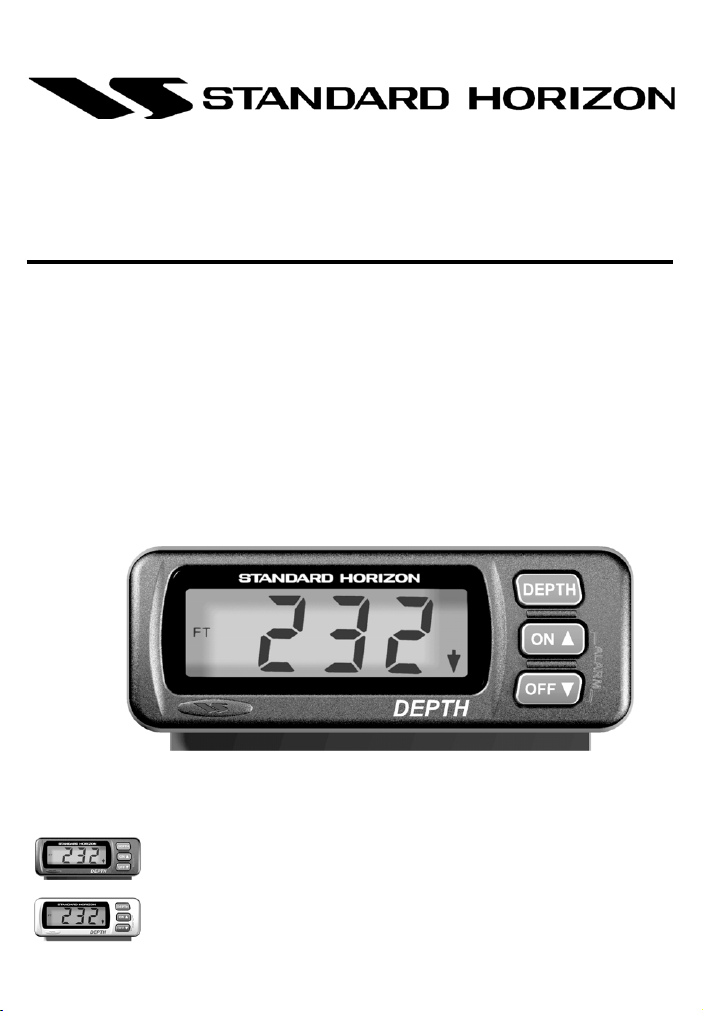
DS35
Digital Depth Sounder
Owner’s Manual
Marine Division of Vertex Standard
Page 2

LIMITED WARRANTY
STANDARD HORIZON MARINE DIVISION OF VERTEX STANDARD warrants to the original purchaser
that each new Marine Product manufactured and/or supplied by STANDARD HORIZON will be free from
defects in materials and workmanship under conditions of normal use and service for a period of one (1)
year from the date of delivery to the Purchaser. STANDARD HORIZON’s liability under this warranty
shall be limited to repair or replacement of the defective product, at STANDARD HORIZON’s option,
under no circumstances shall STANDARD HORIZON be liable for consequential, incidental, or other
damages arising out of or in any way connected with a failure of the product to perform as set forth
herein.
In the event of a defect, malfunction, or failure of the product to conform to specifications during the oneyear warranty period, STANDARD HORIZON will repair or replace, at its option and without charge to the
Purchaser, the product which upon examination by STANDARD HORIZON shall appear to be defective
or not up to factory specifications. To obtain warranty service, the defective product must be returned to
STANDARD HORIZON together with proof of the date of purchase. The Purchaser must pay any
transportation expenses in returning the product to STANDARD HORIZON. STANDARD HORIZON will
examine the product and respond to the Purchaser in approximately four (4) weeks from date of receipt
of the product claimed to be defective.
This limited warranty does not extend to any product which has been subjected to misuse, neglect,
accident, improper installation, or subject to use in violation of the maintenance or operating instructions,
if any, furnished by STANDARD HORIZON, nor does this warranty extend to products on which the serial
number has been removed, defaced, or changed. STANDARD HORIZON reserves the right to make
changes or improvements to its products without notice during subsequent production without incurring
the obligation to install such changes or improvements on previously manufactured or sold products.
To receive warranty service, the Purchaser must deliver the product, transportation and insurance prepaid,
to STANDARD HORIZON Marine Division of Vertex Standard, 115 North Wright Brothers Dr. Salt
Lake City, Utah 84116-2838. Include proof of purchase and date of purchase. STANDARD HORIZON
will return the Product to the Purchaser freight prepaid.
Some states do not allow limitations on the duration of the warranty or exclusions or limitations of incidental
or consequential damages so these limitations or exclusions may not apply to you. This warranty gives
you specific legal rights, which may vary from state to state.
Lifetime Flat Rate Service Program: For the original Purchaser only, for the lifetime of the unit, STANDARD
HORIZON will repair the unit to original specifications.
Note: The flat rate amount is payable by the Purchaser only if STANDARD HORIZON determines that a
repair is needed. After the repair, a 90-day warranty will be in effect from the date of return of the unit to
the Purchaser.
Owner’s Records
Model Serial number
Purchase date Dealer
DS35 User Manual2
Page 3

Contents
1 General Information............................................................................................. 4
1.1 Introduction ................................................................................................. 4
1.2 Front Panel ................................................................................................. 4
1.3 Rear Panel .................................................................................................. 4
2 Controls and Connectors .................................................................................... 5
3 Accessories ......................................................................................................... 6
3.1 Provided with Instrument ............................................................................ 6
3.2 Optional....................................................................................................... 6
3.3 Replacement Parts ..................................................................................... 6
Figure 1. Transducer types ......................................................................................... 7
4 Installation ........................................................................................................... 7
4.1 Instrument Installation ................................................................................ 7
Figure 2. Fuse Panel Connection ................................................................................ 7
Figure 3. Rear panel flush mount installation .............................................................. 7
Figure 4. Gimbal Mount Dimensions ........................................................................... 8
Figure 6. Gimbal Mount ............................................................................................... 8
Figure 5. Flush Mount Dimensions ............................................................................. 8
5 Operation ............................................................................................................. 9
5.1 Primary Operation ...................................................................................... 9
5.1.1 Setting Unit of Measure ...................................................................................... 9
5.1.2 Setting Shallow Alarm ........................................................................................ 9
5.1.3 Setting Deep Alarm .......................................................................................... 10
5.1.4 Alarm On .......................................................................................................... 10
5.1.5 Alarm Off .......................................................................................................... 10
5.1.6 Depth Trend Indicators ..................................................................................... 10
5.2 Secondary Settings .................................................................................. 11
5.2.1 Lamp Intensity .................................................................................................. 11
5.2.2 Keel Offset ........................................................................................................ 11
5.2.3 Display Damping .............................................................................................. 12
5.2.4 Transducer Setting ........................................................................................... 13
5.3 Simulation ................................................................................................. 13
6 Specifications .................................................................................................... 14
7 Maintenance ...................................................................................................... 14
8 Troubleshooting ................................................................................................. 15
8.1 Technical Description ............................................................................... 15
8.2 Troubleshooting ........................................................................................ 15
DS35 User Manual 3
Page 4
1 General Information
Note: Please familiarize yourself with the entire manual and transducer installation guide before
attempting installation.
1.1 Introduction
The DS35 is a high-quality digital depth sounder.
Features include:
• Depth readings from 3 to 200 feet with the
added capability of displaying depth in meters
or fathoms.
• Adjustable depth alarms to alert the user
visually and audibly when the water depth is
less than the shallow and greater than the
deep alarm settings.
• The alarm settings are stored in memory and
are preserved when power is off.
• Display damping is selectable for frequent
readings at critical shallow depths and for
smoother readings at greater depths.
• Trend arrows on the display indicate
increasing or decreasing depth.
• The DS35 will withstand direct water spray on
its front panel without damage.
Note: Actual depth capabilities depend on
transducer used, transducer installation,
bottom conditions and water conditions.
1.2 Front Panel
The display is a back-lit 3½ digit liquid crystal display
(LCD) with an alarm icon (bell), trend arrows, and
alpha flags. It also has a three-button keypad. The
keypad uses tactile and audible feedback to indicate
when a key is pressed. All functions are controlled
entirely by these three keys.
Note: an ON/OFF switch must be installed to
control the power to the instrument.
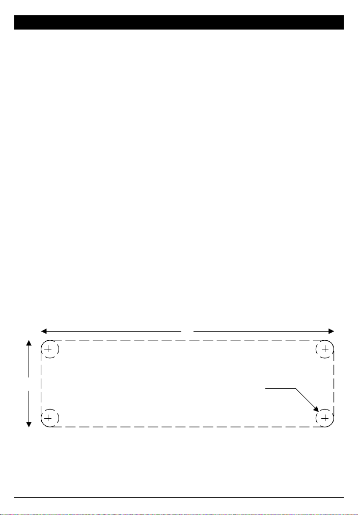
1.3 Rear Panel
The rear panel contains a cable terminated with an
RCA phono receptacle for connection to the
transducer and a 3.5ft. 12 VDC power cable with
insulated stripped and tinned red and black wires.
37/8"
"
16
/
7
1
Diameter ¼" (6.3mm)
DS35 User Manual4
Page 5
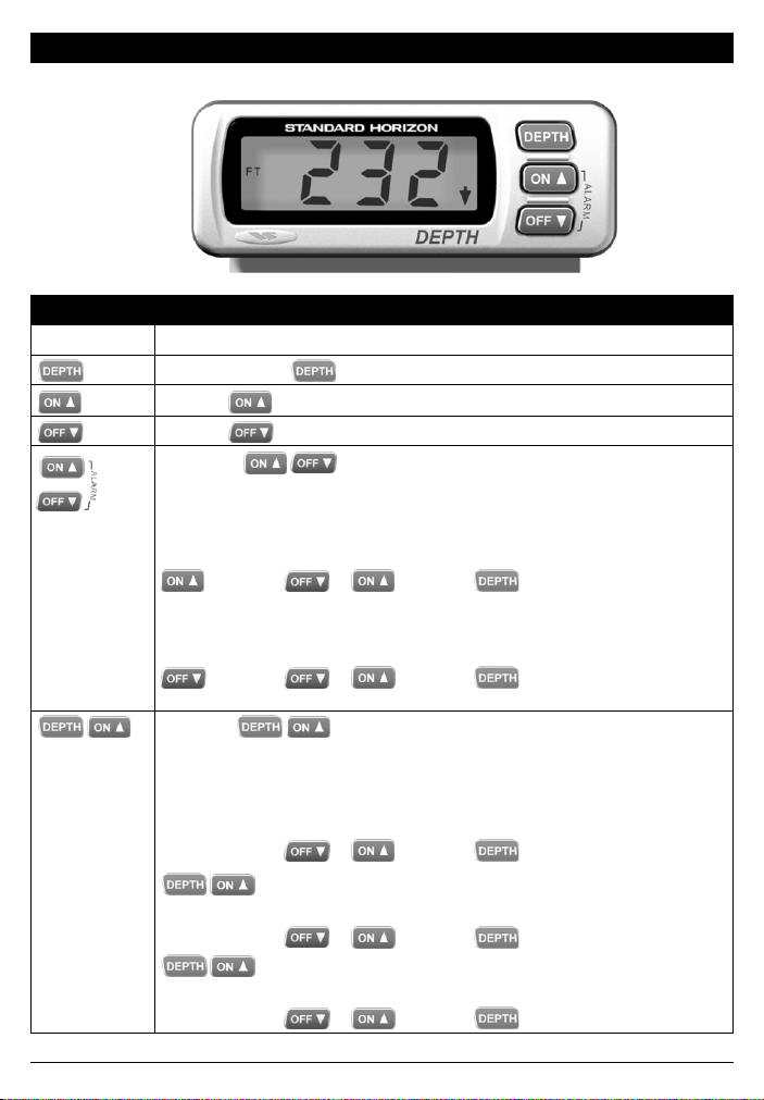
2 Controls and Connectors
Operating Controls
Keys Functions
Press and hold the key three seconds to change units “MTR”, “FT” and “FA”.
Press the key to turn on the alarm.
Press the key to turn off the alarm.
Press both
mode. The display will alternate between “UP” and “LO”.
“UP” = deep and “LO” = shallow.
“OFF” = alarm disabled, scroll to set depth.
Press Scroll Exit
“UP” or
or
Press Scroll Exit
“LO” or
keys and hold for three seconds to enable the alarm setting
Press both keys and hold for three seconds to enable the secondary
mode which includes lamp intensity, keel offset, and damping adjustments.
Scroll to adjust.
Scroll Exit
“LO” - off, “L1”,
“L2”, or “L3”
Press both keys to step to Keel Offset.
“+0.0”
Press both keys to step to Damping
“d1”, “d2”, or “d3”
DS35 User Manual 5
or
Scroll Exit
or
Scroll Exit
or
Page 6

3 Accessories
3.1 Provided with Instrument
• Power Cable • Flush mount kit
• Mounting bracket • Mounting bracket hardware
3.2 Optional
DC35 ............................................................................................................................................. Dust Cover
EX345D ............................................................................................... 15-foot Transducer Extension Cable
DST50 ............................................................................................. Nylon Low-Profile Thru-hull Transducer
DST51 ........................................................................................................... Transom-Mounting Transducer
DST52 ........................................................................................... Bronze Long-Stem Thru-hull Transducer
DST53 .......................................................................................................... Bronze Low-Profile Transducer
DST55 ............................................................................................................................... In-hull Transducer
FBT52 ...................................................................................................................... Fairing block for DST52
DST50 Nylon Low Profile Transducer
2.94"
DST51 Transom-Mount Transducer
2.58"
(66mm)
DST52 Bronze Long-Stem
Thru-hull Transducer
1.4"
5.96"
¾" - 14 NPS
1.13"
1.82"
2.94"
3.12"
0.19"
0.19"
2" - 12 THDS / IN
DST53 Bronze Low Profile Transducer
2" - 12 THDS / IN
3.125"
3.50"
DST55 In-hull Transducer
3.51"
13º
4.35" (110mm)
2.75"
1.40" (36mm)
2.125"
2.24"
(57mm)
Figure 1. Transducer types
3.3 Replacement Parts
The following parts may be ordered from the STANDARD HORIZON Parts Department.
To order, call: 562-404-2700 Ext 351
Part ........................................................................................................................................... Part Number
Flush Mount Panel Gasket ........................................................................................................ 108007023A
Flush Mount Bracket Stud/Washer (2) ..................................................................................... 113001003A
Flush Mount Bracket Stud/Washer Screw (2) .......................................................................... 569004022A
Flush Mount Mounting Bracket ................................................................................................. 160004020A
Flush Mount Mounting Nuts (2) ................................................................................................ 580010123A
Gimbal Screws (2) ..................................................................................................................... 154001016A
Gimbal Screw Washers (2) ....................................................................................................... 581003030A
Gimbal Mounting Bracket .......................................................................................................... 160003020A
DS35 User Manual6
Page 7

4 Installation
4.1 Instrument Installation
The instrument can be easily
installed in different types of
instrument panels. Refer to Figures
2, 3, 4, and 5 for the following steps.
1. Select a suitable location for
the instrument. When selecting
the location for mounting, the
following are recommended:
• Controls of the instrument
must be accessible to the
user.
• Electrical connections must
be routed to their
connections as directly as
possible.
NOTE: The instrument must be
connected through a switch to
provide a means of turning the
instrument on and off. The red
lead of the power cable should
be connected to a 1-Ampere
circuit breaker then to the
positive terminal of the power supply. The
solid black lead should be connected to the
negative terminal.
If your boat has an electrical system, there is probably
a fuse panel in the console area, which can be used
to connect the instrument. If a fuse terminal is
available, use crimp-on type connectors to match
the fuse panel terminal. See Figure 2.
2. Fasten the instrument with either the gimbal
Figure 3. Rear panel flush mount installation
Figure 2. Fuse Panel Connection
Fuse Panel
3. Obtain the power from a 12V source as
4. Connect the RCA phono plug on the
Stud/Washer Screws (2)
Ground
Instrument
Power Cable
mounting bracket or the flush mount mounting
bracket and nuts provided.
directly as possible. Avoid power circuits which
share loads with ignition, alternators, radio
transmitters, etc. Excessive electrical noise
associated with such devices may prevent the
instrument from operating properly.
transducer cable to the instrument.
Flush Mount Bracket Stud/Washers (2)
Flush Mount Panel Gasket
Flush Mounting Bracket
Flush Mounting
Nuts (2)
Pattern for cutting
hole in dashboard
17/16"
37/8"
DS35 User Manual 7
Page 8

Figure 4. Gimbal Mount Dimensions
2¼" (57mm)
2"
(51mm)
Figure 5. Flush Mount Dimensions
Dashboard (1/8 to 11/16" (3 to 27mm))
1¾" (44mm)
Gasket
Figure 6. Gimbal Mount
Washers (2)
29/16" (65mm)
2" (51mm)
Bracket
47/8" (124mm)
43/16" (106mm)
Nut (2)
Stud (2)
Mounting Surface
Trunnion
Screws (2)
Mounting
Bracket
Screws (2)
Washers (2)
Mounting
Bracket
Trunnion
Screws (2)
DS35 User Manual8
Page 9

5 Operation
5.1 Primary Operation
5.1.1 Setting Unit of Measure
To select the unit of measure, press and hold the
key for three seconds. The display changes.
Depth can be displayed in feet, meters, or fathoms.
Press and hold
for 3 seconds
Press and hold
for 3 seconds
Press and hold
for 3 seconds
If the water depth is greater than 200 feet or if too
much aerated water is passing over the transducer
(refer to sections 4.2.2, 4.2.3, 4.2.4), the numeric
section of the display will show two horizontal lines.
Press and hold
for 3 seconds
Display alternates
between these two
Press to set
Shallow Alarm
Press to set
Alarm Depth
or
Press until
display
decreases to
OFF
Press to exit
or
Depth Display
5.1.2 Setting Shallow Alarm
Press and hold both the keys for three
seconds to enable the alarm mode. Press the
key to select the shallow alarm. “LO” displays
momentarily. Press either the
to change the setting. Press the
or key
key to exit
to normal operation. Or to disable the shallow alarm,
press the
key until the display decreases to
“OFF”.
DS35 User Manual 9
Press to exit
Depth Display
Page 10

5.1.3 Setting Deep Alarm
Press and hold both the keys for three
seconds to enable the alarm mode. Press the
key to set the deep alarm. “UP” displays momentarily.
Press either the
setting. Press the
the deep alarm, press the
decreases to “OFF”.
Press and hold
for 3 seconds
Display alternates
between these two
or key to change the
key to exit. Or to disable
key until the display
5.1.4 Alarm On
To turn the alarm, press the key. The alarm
icon will appear.
Press
Depth Alarm Icon
5.1.5 Alarm Off
To turn off the alarm, press the key. The alarm
icon will disappear.
Press to set
Deep Alarm
Press to set
Alarm Depth
Press until display
decreases to OFF
or
Press to exit
or
Depth Display
Press to exit
Depth Display
Press
No Depth Alarm Icon
5.1.6 Depth Trend Indicators
If there is a continuing increase or decrease in water
depth, a trend arrow will be displayed to show the
direction of change.
Increasing Trend
Decreasing Trend
DS35 User Manual10
Page 11

5.2 Secondary Settings
To access the secondary settings, press and hold
the
Succeeding depressions of the
and keys for three seconds.
and
keys will step the display through each level of the
secondary settings.
The levels accessible, in succession, are:
• Lamp Intensity
• Keel Offset
• Display Damping
• Transducer Settings
5.2.1 Lamp Intensity
Press and hold the and keys for three
seconds to go to the LAMP mode. To adjust the
lamp intensity, press either the
Intensities of 1, 2 or 3 can be selected; 0=OFF. Press
the
key to exit, or press the and
keys to advance to the keel offset mode.
or key.
5.2.2 Keel Offset
In the Secondary mode, with the Lamp Intensity level
displayed, press the and keys to step
to the Keel Offset display; “+0.0” will be displayed
for adjustment. Keel Offset can be adjusted for any
of the following situations. Displayed depth will be
adjusted accordingly.
• Depth below the water line (positive adjustment
– depending on the distance the transducer is
below the water line)
• Depth below the keel (negative adjustment –
depending on the distance the keel is below
the bottom of the transducer)
• Depth below the transducer (set offset to 0.0)
Note: The keel offset quantity may be entered
in either feet, meters, or fathoms in 0.1 unit
increments.
Press the or key to set the offset depth.
Press the key to exit, or press the
and keys to advance to the Display Damping
mode.
Press both
Hold for 3
seconds
Press One
Press both to
step to next
level: Keel
Offset
or
or
Press to exit
Press both
Hold for 3 seconds
Press Both
Press One
Press both to
step to next
level: Display
Damping
or
or
Press to exit
DS35 User Manual 11
Page 12

5.2.3 Display Damping
The user has a choice of three levels of display
damping. Damping controls the speed at which the
LCD display is able to record and display the actual
changes in the water depth. Level ‘d1” allows the
display to change very rapidly; it is selected when
operating in shallow water at higher speeds. Level
‘d2” or “d3” may be required in deeper or deepest
water where passing schools of fish, thermal layers,
or debris may introduce random echoes.
With the instrument in the keel offset setting, press
the
damping setting. Press the either
key to select an update rate of “d1”, “d2” or “d3”.
Press the key to exit, or press the
and keys to advance to the transducer setting
mode.
and keys to step to the display
or
Press both
Hold for 3 seconds
Press Both
Press Both
Press One
Press both to
step to next
level: Set
Transducer
or
or
or
Press to exit
DS35 User Manual12
Page 13

5.2.4 Transducer Setting
The Transducer Setting function enables the user
to optimise the operation of the DS35 for the
particular transducer installed. Transducer
performance varies widely, larger diameter
transducers produce strong signals resulting in
improved deep water performance but can suffer
from reduced shallow water performance, due to
transducer ringing. Smaller transducers produce the
opposite effect, with improved shallow water
performance and reduced deep water performance.
There are three values of transducer settings (1 to
3). The lower numbers improve the shallow water
performance and may produce reliable readings to
below 3 feet. It is recommended to use the lowest
number possible if shallow water performance is
important. It must also be noted that in situations
where the DS35 is tracking the bottom and displaying
a consistent depth but occasionally displaying “--”
or erroneous depths of 3 to 4 feet, that this generally
indicates the transducer setting is too low and should
be increased. The transducer settings only affect
the instrument operation in the 2.5 to 4 feet region.
The transducer settings have no affect in water
deeper than 4 feet.
The transducer setting is a secondary function and
can be accessed as shown in the diagram below.
Press both
Hold for 3 seconds
Press Both
Press Both
Press Both
Press One
5.3 Simulation
Simulation is a feature used to demonstrate
the operation of the instrument. The owner
may activate the simulation mode by
holding the key down and turning
or
or
Press to exit
Press and hold while
power is being turned on
Right-hand
digit counts
up or down
on the power to the instrument. Simulation
is in operation when the right-hand digital
of the display counts up or down one digit
at a time. To disable simulation mode, turn
off the power and hold the
key down
as power is turned on.
Turn instrument power off
Press and hold
while power is
being turned on
DS35 User Manual 13
Page 14

6 Specifications
Dimensions
• 4.875W x 2.25D x 2H inches (124W x 57D x
51H mm)
Mounts
• Flush/Gimbal
Flush Mount
• 4.25 x 1.375 inch (108 x 35mm) hole
• Depth behind panel 2.25 inch (57mm)
Display
• Liquid Crystal 3½ digit numeric, 0.75in. (19mm)
high
Color
• Black or white
Water Integrity
• Front will withstand direct spray
Depth Display
• Feet:
3 to 200 (3 to 19.9 in tenths, 20 to 200 in
whole numbers)
• Meters:
0.8 to 61 (0.8 to 9.9 in tenths, 10 to 61 in
whole numbers)
• Fathoms
0.5 to 33 fathoms
Accuracy
• +/- 2%
Alarms
• Depth: shallow and deep, adjustable, non-volatile
Options (keypad selectable)
• Illumination Intensity Level (3-step)
• Damping level (5, 10 & 15%)
• Keel Offset (Adjustable, +/- 10 units)
Trend Indication
• Up and down arrows
Sensitivity
• 0.4 mV RMS at 30+ feet
Transducer
• Transom, Thru-hull option, or In-hull options
600 ohm, 1500 pF parallel impedance
Frequency
• 201 +/- 1 kHz
Operating Voltage
• 13.8 VDC +/- 20%
Operating Temperature
• 32° to 122°F (0° to 50°)
Current Drain
• 70 mA nominal
Output Power
• 50 watts RMS
RF Interference
• 6 dB maximum quieting on any marine radio
channel with 3 dB gain antenna within 1 meter
of the DS35
7 Maintenance
Your depth sounder is designed for years of trouble free operation assuming proper installation and care are
provided. Following the operation and installation guidelines in this manual should ensure optimum performance
of the instrument. In the unlikely event that the instrument shall fail to perform or shall need servicing,
contact:-
Standard Horizon
Factory Repair Facility
115 North Wright Brothers Drive
Salt Lake City, UT 84116
Telephone number (800) 366-4566
Technical support telephone number (562) 404-2700
Fax number (801) 359-4122
E-mail address marinetech@vxstdusa.com
www.standardhorizon.com
DS35 User Manual14
Page 15

8 Troubleshooting
8.1 Technical Description
The transmitter generates pulses (201 kHz) of ultrasonic energy, radiated towards the bottom of the sea.
At exactly the moment a pulse leaves the transmitter, the transmitter is turned off, and the transducer receiver
is turned on.
The sound energy echoes off the bottom and returns to the transducer. The echo is converted to digital
signals for the microcomputer which computes the depth based on the time it takes to receive a return echo.
The longer it takes for the energy to reach the bottom and return to the transducer, the deeper the water.
The microcomputer sends the computed depth to the instrument display.
8.2 Troubleshooting
1 No display:
• Check DC power connections and DC polarity with voltmeter. Voltage must be between 10.7 and 16.6
volts.
2 No depth reading “--” at all depths:
a Check the transducer for growth or multiple coats of paint.
b Check the transducer cable for cuts and sharp bends.
c Substitute the transducer with a known good Standard Horizon transducer, hold it over the side of the
boat into the water to see if the instrument functions. This isolates cause of problem (transducer or
instrument).
3 Erratic readings while moored
• Check the transducer for growth or multiple coats of paint.
4 Erratic readings while underway
• Cavitation (air) under the face of the transducer. Review installation and reinstall if necessary.
5 When power is applied, display right-hand digit counts up or down
• See section 5.3 Simulation
6 Erratic readings only when engine is running
a Reroute DC and transducer cables away from engine, ignition wires and battery cables.
b Add feed-thru filter capacitor on the positive terminal of the ignition coil.
c Add alternator whine filter to alternator.
d Replace spark plug wire with resistive type.
DS35 User Manual 15
Page 16

Marine Division of Vertex Standard
17210 Edwards Road
Cerritos, CA 90703
Telephone: 562/404-2700
STANDARD HORIZON
ALL RIGHTS RESERVED
PRINTED IN NEW ZEALAND
April 2001
EED4100BD
1951124A MN000130
 Loading...