

Stamina 55-1723 Owner's Manual
Owner's Manual
W ARNING
Exercise can present a health
risk. Consult a physician
before beginning any exercise
program with this equipment.
If you feel faint or dizzy,
immediately discontinue use
of this equipment. Serious
bodily injury can occur if this
equipment is not assembled
and used correctly. Serious
bodily injury can also occur if
all instructions are not
followed. Keep others and
pets away from equipment
when in use. Always make
sure all bolts and nuts are
tightened prior to each use.
Follow all safety instructions in
this manual.
CAUTION:
Weight on this product should not exceed 250 lbs.
This Product is Produced Exclusively by
2040 N. Alliance, Springfield, MO 65803
2009, 06
Customer Service Number
1 (800) 375-7520
www.staminaproducts.com
When calling for parts or
service, please specify the
following number.
55-1723
ST AMINA PRODUCTS
MADE IN CHINA
Product May Vary Slightly
From Pictured.
2007 Stamina Products, Inc.

T ABLE OF CONTENTS
Page Page
Safety Instructions 2
Before You Begin 4
Hardware Identification Chart 5
Assembly Instructions 6
Set Up Instructions 11
Operational Instructions 12
Storage 14
Maintenance 14
Conditioning Guidelines 15
Warm-up and Cool-Down 16
Warranty 17
Product Parts Drawing 18
Parts List 19
Notes 21
Fax/Mail Ordering Form 22
SAFETY INSTRUCTIONS
WARNING:
1.
Read all warnings posted on the CT2.0 CROSS TRAINER.
2.
Read this owner's/user's manual and follow it carefully before using the CT2.0 CROSS TRAINER.
3.
We recommend that two people be available for assembly of this product.
4.
Keep children away from the CT2.0 CROSS TRAINER. Do not allow children to use or play on the
CT2.0 CROSS TRAINER. Keep children and pets away from the CT2.0 CROSS TRAINER when it
is in use.
5.
It is recommended that you place this exercise equipment on an equipment mat.
6.
Set up and operate the CT2.0 CROSS TRAINER on a solid level surface. Do not position the CT2.0
CROSS TRAINER on loose rugs or uneven surfaces.
7.
Make sure that adequate space is available for access to and around the CT2.0 CROSS TRAINER.
8.
Inspect the CT2.0 CROSS TRAINER for worn or loose components prior to use.
9.
Tighten/replace any loose or worn components prior to using the CT2.0 CROSS TRAINER.
10.
Consult a physician prior to commencing an exercise program. If, at any time during exercise, you
feel faint, dizzy , or experience p ain, stop and consult your physician.
11.
Follow your physician's recommendations in developing your own personal fitness program.
12.
Always choose the workout which best fits your physical strength and flexibility level. Know your
limits and train within them. Always use common sense when exercising.
13.
Do not wear loose or dangling clothing while using the CT2.0 CROSS TRAINER.
14.
Never exercise in bare feet or socks; always wear correct footwear, such as running, walking, or
crosstraining shoes. Be sure that they fit well, provide foot support and feature non-skid rubber
soles.
15.
Be careful to maintain your balance while using, mounting, dismounting, or assembling the CT2.0
CROSS TRAINER, loss of balance may result in a fall and serious bodily injury .
16.
Keep both feet firmly and securely on the pedal caps while exercising.
17.
The CT2.0 CROSS TRAINER should not be used by persons weighing over 250 pounds.
18.
The CT2.0 CROSS TRAINER should be used by only one person at a time.
19.
The CT2.0 CROSS TRAINER is for consumer use only. It is not for use in public or semipublic
facilities.
20.
Use two people to move the CT2.0 CROSS TRAINER.
To reduce the risk of serious injury, read the following Safety Instructions before
using the CT2.0 CROSS TRAINER.
WARNING:
Before starting any exercise or conditioning program you should consult with your personal
physician to see if you require a complete physical exam. This is especially important if you
are over the age of 35, have never exercised before, are pregnant, or suffer from any
illness. READ AND FOLLOW THE SAFETY PRECAUTIONS. FAILURE TO FOLLOW
THESE INSTRUCTIONS CAN RESUL T IN SERIOUS BODILY INJURY.
2

CALL US FIRST
THANK YOU FOR PURCHASING THE
STAMINA
T o help you get started, we have pre-assembled most of your
CT2.0 CROSS TRAINER at the factory with the exception
of those few part s left unassembled for shipping purposes.
Simply follow the few assembly instructions set forth in this manual.
With regular workouts you will be getting your body into shape
and on your way to achieving a happier and healthier lifestyle.
Should you have any questions,
please call our Customer Service Department toll-free number,
Monday - Thursday, 7:30 A.M. - 5:00 P.M. Central Time.
Friday, 8:00 A.M. - 3:00 P.M., Central Time.
TELEPHONE
CUSTOMER SERVICE
Tel: 1 (800) 375-7520
CUSTOMER SERVICE
CT2.0 CROSS TRAINER
1 (800) 375-7520
FAX
Fax: (417) 889-8064
cust-srvc@staminaproducts.com
ONLINE
CUSTOMER SERVICE
parts@staminaproducts.com
www.staminaproducts.com
STAMINA PRODUCTS, INC.
Springfield, MO. 65801-1071
MAIL
A TTN: Customer Service
P.O. Box 1071
3
BEFORE YOU BEGIN
Thank you for choosing the CT2.0 CROSS
TRAINER. We take great pride in producing this
quality product and hope it will provide many hours
of quality exercise to make you feel better, look better
and enjoy life to its fullest.
Yes, it's a proven fact that a regular exercise
program can improve your physical and mental
health. Too often, our busy lifestyles limit our time
and opportunity to exercise. The CT2.0 CROSS
TRAINER provides a convenient and simple method
to begin your assault on getting your body in shape
and achieving a happier and healthier lifestyle.
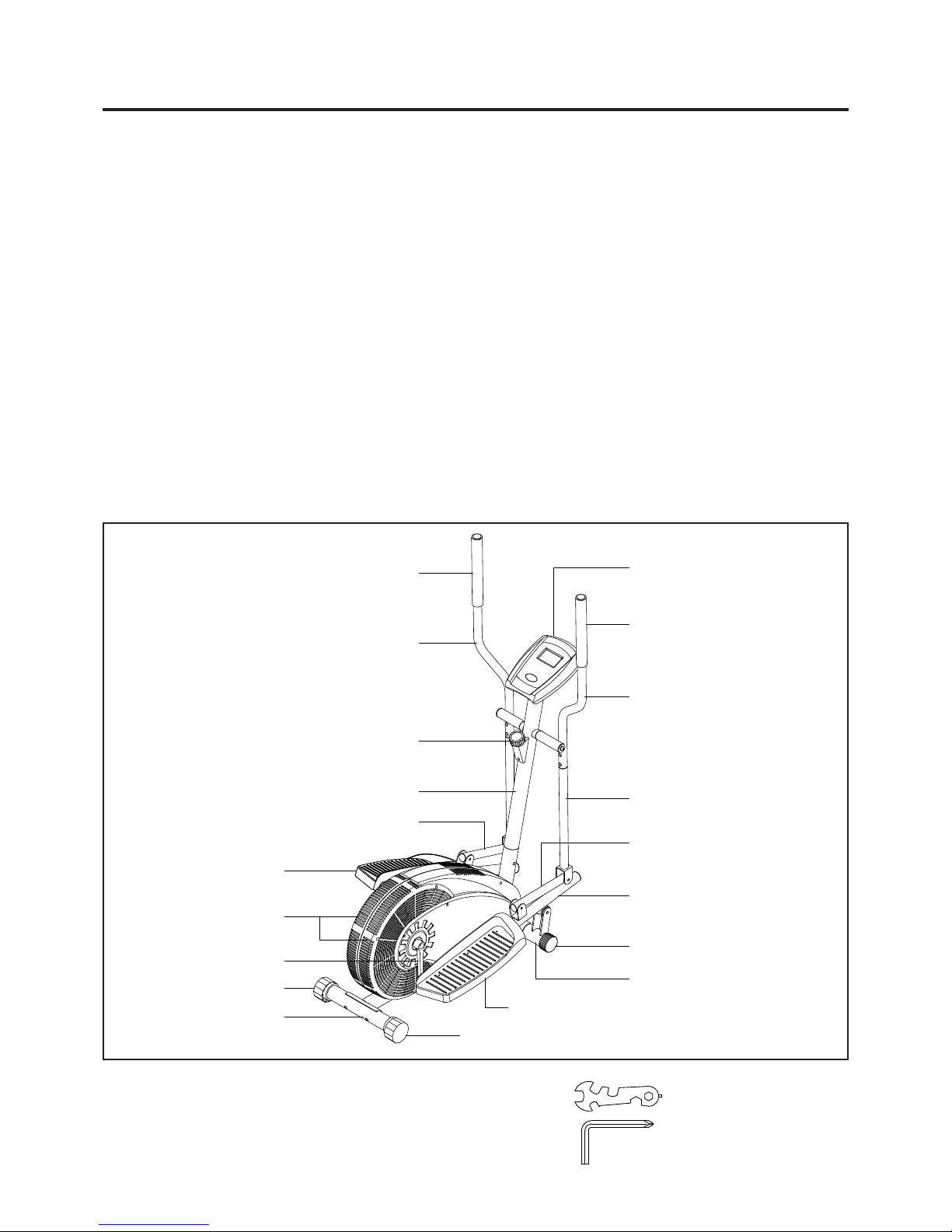
Before reading further, please review the drawing
below and familiarize yourself with the parts that are
labeled.
Read this manual carefully before using the CT2.0
CROSS TRAINER.
Foam Grip
Although Stamina construct s it s products with the
finest materials and uses the highest standards of
manufacturing and quality control, there can
sometimes be missing parts or incorrectly sized
parts. If you have any questions or problems with
the parts included with your CT2.0 CROSS
TRAINER, please do not return the product. Contact
us FIRST!
If a part is missing or defective, please call us toll
free at 1-800-375-7520 (in the U.S.). Our Customer
Service St aff is available to assist you from 7:30 A.M.
to 5:00 P .M. (Central T ime) Monday through Thursday
and 8:00 A.M. to 3:00 P.M. (Central Time) on Friday.
If you would like to contact us online, go to our
website at www.staminaproduct s.com and access the
Customer Service section.
Be sure to have the name and model number of
the product available when you contact us.
Meter
Pedal Cap
Fan Cages
Crank
Leveling Cap
Rear Stabilizer
Left Handlebar
T ension Knob
Upright
Linkage
Foam Grip
Right Handlebar
Lower Pivoting Arm
Linkage
Pedal Arm
Endcap
Front Stabilizer
Pedal Cap
Leveling Cap
THE FOLLOWING TOOLS ARE INCLUDED FOR ASSEMBLY : Wrench
Allen Wrench (6mm)
4
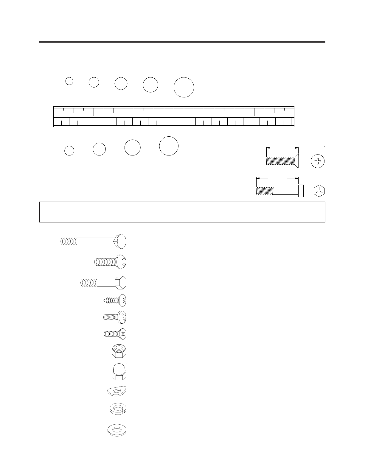
HARDWARE IDENTIFICATION CHART
This chart is provided to help identify the hardware used in the assembly process. Place the washers, the
end of the bolts, or screws on the circles to check for the correct diameter . Use the small scale to check the
length of the bolts and screws.
3/16" 5/16" 1/2"3/8"1/4"
INCHES
11/2021/2 31/2 41/2 51/2 61/2
0 10 20 30 40 50 60 70 80 90 100 110 120 130 140 150
MILLIMETERS
6 8 10 12
NOTICE: The length of all bolts and screws except those with flat heads is
measured from below the head to the end of the bolt or screw.
Flat head bolts and screws are measured from the top of the
head to the end of the bolt or screw.
After unpacking the unit, open the hardware bag and make sure that you have all the following items.
Some hardware may be already attached to the part.
length
length
in.
mm.
Part No. and Description Qty
64 Carriage Bolt (M8 x 1.25 x 65mm) 4
65 Bolt, Button Head (M8 x 1.25 x 15mm) 4
66 Bolt, Button Head (M8 x 1.25 x 20mm) 2
67 Bolt, Button Head (M8 x 1.25 x 48mm) 2
73 Bolt, Hex Head (M6 x 1 x 38mm) 4
76 Screw, Round Head (M5 x 15mm) 6
77 Screw, Round Head (M5 x 0.8 x 15mm) 4
78 Screw, Flat Head (M5 x 0.8 x 12mm) 1
80 Nylock Nut (M8 x 1.25) 2
86 Acorn Nut (M6 x 1) 4
87 Acorn Nut (M8 x 1.25) 4
88 Arc Washer (M6) 4
89 Arc Washer (M8) 8
90 Lock Washer (M6) 4
91 Lock Washer (M8) 10
48 Large Washer (M8 x 32mm x 2mm thick) 2
53 Plastic Washer (M8 x ø18 x 2mm thick) 4
57 Large Washer (M16 x 0.5mm thick) 2
5
ASSEMBLY INSTRUCTIONS
Place all parts from the box in a cleared area and position them on the floor in front of you. Remove all
packing materials from your area and place them back into the box. Do not dispose of the packing materials
until assembly is completed. Read each step carefully before beginning. If you are missing a part please
call our toll-free number for assistance 1 (800) 375-7520 or e-mail us at:
parts@staminaproducts.com
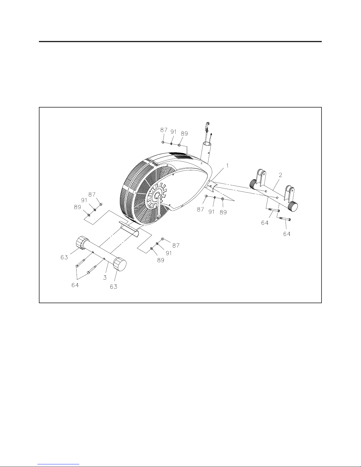
STEP 1
Attach the FRONT STABILIZER(2) onto the MAIN FRAME(1) with CARRIAGE BOLTS(M8x1.25x65mm)
(64), ARC W ASHERS(M8)(89), LOCK WASHERS(M8)(91), and ACORN NUTS(M8x1.25)(87).
STEP 2
Attach the REAR ST ABILIZER(3) onto the MAIN FRAME(1) with CARRIAGE BOLTS(M8x1.25x65mm)(64),
ARC WASHERS(M8)(89), LOCK W ASHERS(M8)(91), and ACORN NUTS(M8x1.25)(87).
NOTE: Y ou can adjust the LEVELING CAPS(63) on the REAR ST ABILIZER(3) to keep the CT2.0 CROSS
TRAINER stable.
6
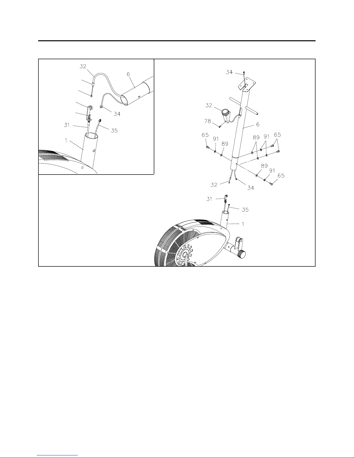
ASSEMBLY INSTRUCTIONS
Metal Fitting
Cable End
Bracket
Spring Hook
STEP 3
Refer to the illustration. Slide the CABLE on the TENSION KNOB(32) through the UPRIGHT(6). CAUTION:
Be careful not to damage the
UPRIGHT(6) with
FLA T HEAD SCREW(M5x0.8x12mm)(78).
CONNECTION WIRE(34). Attach the TENSION KNOB(32) onto the
STEP 4
Refer to the inset drawing. Lay the UPRIGHT(6) on the floor close to the front of the MAIN FRAME(1). Turn
the TENSION KNOB(32) on the UPRIGHT(6) counterclockwise as far as it can go, so the cable end extends
out of the metal fitting as far as possible. Connect the CABLE END of the TENSION KNOB(32) into the
SPRING HOOK on the end of the TENSION CABLE(31). Pull the CABLE on the TENSION KNOB(32)
firmly and insert the cable through the slot in the bracket. Then insert the MET AL FITTING on the end of the
CABLE of the TENSION KNOB(32) into the hole at the end of the slot in the BRACKET. Adjust the TENSION
KNOB(32) and verify that the SPRING HOOK moves when the TENSION KNOB(32) is adjusted.
STEP 5
Plug the SENSOR WIRE(35) firmly into the CONNECTION WIRE(34). CAUTION: Be careful not to damage
the SENSOR WIRE(35) and CONNECTION WIRE(34) when assembling the UPRIGHT(6).
STEP 6
Insert the UPRIGHT(6) into the MAIN FRAME(1) and secure with BUTTON HEAD BOL TS(M8x1.25x15mm)
(65), ARC WASHERS(M8)(89), and LOCK W ASHERS(M8)(91). Do not tighten the bolt s until STEP 10.
7
 Loading...