

Stamina 55-1529A Owner's Manual
55-1529A
STAMINA PRODUCTS
MADE IN CHINA
Product May Vary Slightly
From Pictured.
Owner's Manual
CAUTION: 1. Weight on this product should not exceed 250 lbs.
2. Class H equipment: This equipment is for home
use only. It is not for commercial use.
! WARNING !
Exercise can present a he alth
risk. Consult a physician
before beginning any exercise
program with this equipment.
If you feel faint or dizzy,
immediately discontinue use
of this equipment. Serious
bodily injury can occur if this
equipment is not assembled
and used correctly. Serious
bodily injury can also occur if
all instructions are not
followed. Keep others and
pets away from equipment
when in use. Always make
sure all bolts and nuts are
tightened prior to each use.
Follow all safety instructions in
this manual.
When calling for parts or
service, please specify the
following number.
2005, 08
2040 N. Alliance, Springfield, MO 65803
Customer Service Number
1 (800) 375-7520
www.staminaproducts.com
This Product is Produced Exclusively by
2005 Stamina Products, Inc.

TABLE OF CONTENTS
Page Page
Safety Instructions 2
Before Y ou Begin 4
Hardware Identification Chart 5
Assembly Instructions 6
Operational Instructions 10
Maintenance Instructions 12
Warranty 13
Product Parts Drawing 14
Parts List 15
Notes 16
Fax/Mail Ordering Form 18
SAFETY INSTRUCTIONS
Extreme obesity
Glaucoma, retinal detachment or conjunctivitis
Pregnancy
Spinal injury, Cerebral Sclerosis, or acutely swollen joints
Middle ear infection
High blood pressure, Hypertension, Recent stroke or Transient ischemic attack
Heart or circulatory disorders for which you are being treated
Hiatus hernia or Ventral hernia
Bone weaknesses including Osteoporosis, Unhealed fractures, Medullary pins, or
Surgically implanted orthopedic supports.
Use of anti-coagulants including Aspirin in high doses.
WARNING:
Before using this equipment you should consult with your personal physician to see if inversion
equipment is a ppropriate f or you. Do not use this equipment without your physicia n's approval. Do not
use this equipment if you have any of the following conditions or ailments:
2
WARNING:
1.
2.
3.
4.
5.
6.
7.
8.
9.
10.
11.
12.
13.
14.
15.
16.
17.
Do not use the Assisted Inversion Pro alone. Always have a helper availa ble in case assistance is needed
in recovering from the decline position.
Make sure that the Assisted Inversion Pro is properly a ssembled before use. Pay close attention to Step 13 on
page 9.
Make sure that the Pad T ubes a s a sse mbled with the ends pointed down a s directed in STEP 5 on page 7. The
ends must be pointed downward to properly secure the users feet in place during inversion. Improper a ssembly
will allow the users feet to come loose allowing the user to fall from the inversion table.
Do not use the Assisted Inversion Pro until you have verified your height setting. Failure to use the proper
height setting can result in difficulty recovering from the decline position. See HEIGHT ADJUSTMENT
instructions on page 10.
Always make sure that Heel Holder mechanism is properly locked when using the Assisted Inversion Pro.
Adjust the Nylon Straps to an angle of 15 to 20 degrees a nd use this setting until you have verified your height
setting and become familiar with the Assisted Inversion Pro.
You must understand how to recover from the fully inverted position before using the fully inverted position.
Read the RECOVER Y FROM LOCKED POSITION se ction at the bottom of page 12 BEFORE using the fully
inverted position.
Do not allow children to use or play on the Assisted Inversion Pro.
Keep small children and pets away from the Assisted Inversion Pro at all times.
The Assisted Inversion Pro should not be used by persons weighing more than 250 lbs.
The Assisted Inversion Pro should not be used by persons over 6 feet 6 inches tall.
Use the Assisted Inversion Pro only on a level surface.
W ear a ppropriate clothing when exercising; do not wear loose clothing that could become caught in the Assisted
Inversion Pro.
Be sure that there is enough room for the bed to rotate completely.
Use the Assisted Inversion Pro only as described in the manual.
The safety level of the Assisted Inversion Pro can be maintained only if it is examined regularly for damage
and wear.
This equipment is for home use only. It is not for commercial use.
To reduce the risk of serious injury, read the following safety instructions before
using the
Assisted Inversion Pro.

THANK YOU FOR PURCHASING THE
Assisted Inversion Pro
To help you get started, we have pre-assembled most of your
Assisted Inversion Pro at the factory with the exception
of those few parts left unassembled for shipping purposes.
Simply follow the few assembly instructions set forth in this manual.
Within a few minutes you will be getting your body into shape and on your
way to achieving a happier and healthier lifestyle.
Should you have any que stions,
please call our Customer Service Department toll-free number,
1 (800) 375-7520
Monday - Friday, 8:00 A.M. - 5:00 P.M., Central Time.
CALL US FIRST
3
BEFORE YOU BEGIN
Thank you f or choosing the Assisted Inversion
Pro. We take great pride in producing this quality
product and hope it will provide ma ny hours of quality
exercise to make you feel better , look better and enjoy
life to its fullest.
Yes, it's a proven fact that a regular exercise
program can improve your physical and mental
health. Too often, our busy lifestyles limit our time
and opportunity to exercise. The
Assisted
Inversion Pro provides a convenient and simple
method to begin your assault on getting your body in
sha pe and a chieving a ha ppier and healthier lifestyle.
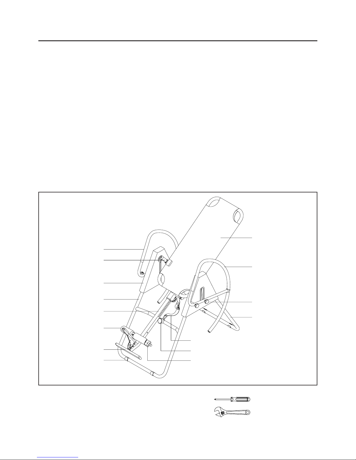
Before reading further , ple ase review the drawing
below and familiarize yourself with the parts that are
labeled.
Read this manual carefully before using the
Assisted Inversion Pro.
4
Footrest
Right Pivot Arm
Front Frame
Height
Adjustment Beam
Foam Pad
Right Protective
Cover
Round Stand
Buckle Strap
Bumper
Heel Holder
Nylon Bed
Handrail
Rear Frame
Locking Knob
Handrail
THE FOLLOWING TOOLS ARE REQUIRED FOR ASSEMBLY : Phillips Screwdriver
Adjustable Wrench
Although Stamina tries to manufa cture its products
with the finest materials and uses the highest
standards of ma nufacturing, occasionally a part that
does not fit, is the incorrect size, or is otherwise
inappropriate is found. Even with the highest
inspection and quality controls in place these things
will happen occasionally. Please do not return the
product. For your convenience, Stamina has a
Customer Service Department with a toll-free
number. If a part is missing, does not fit, is the
incorrect size, or is otherwise inappropriate, please
call 1 (800) 375-7520 (in the U.S.) between 8:00 A.M.
and 5:00 P.M. Central T ime, Monday through Friday .
Our operators will be able to assist you with your
problem and the parts will be mailed directly to your
house.
5
Part No. and Description Qty
mm.
in.
INCHES
MILLIMETERS
11/2021/2 31/2 41/2 51/2 61/2
0 10 20 30 40 50 60 70 80 90 100 110 120 130 140 150
6 8 10 12
3/16" 5/16" 1/2"3/8"1/4"
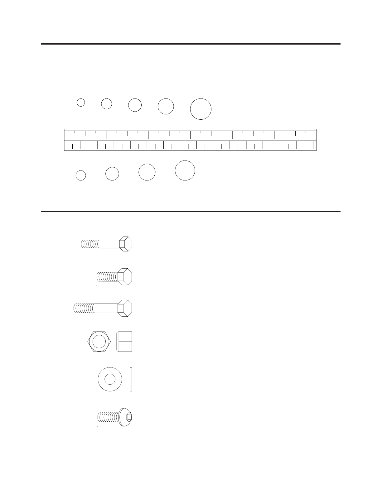
HARDWARE IDENTIFICATION CHART
Place washers, the end of bolts or screws on the
circles to check for the correct size. Use the small
scale to check the sizes of bolts and screws.
This chart is provided to help identify the hardware used in the a ssembly process. After unpacking the unit,
open the hardware bag and make sure that you have the following items:
NOTE: Some of the hardware items listed may be attached to other parts.
43 Bolt, Hex Head (M6 x 1 x 42mm) 1
44 Bolt, Hex Head (M6 x 1 x 48mm) 1
45 Bolt, Hex Head (M8 x 1.25 x 15mm) 2
46 Bolt, Hex Head (M8 x 1.25 x 25mm) 2
47 Bolt, Hex Head (M8 x 1.25 x 50mm) 2
48 Nylock Nut (M6 x 1) 2
49 Nylock Nut (M8 x 1.25) 6
50 Washer (M6) 4
51 Washer (M8) 10
52 Large Washer (M8) 2
53 Large Washer (M6) 2
54 Bolt, Button Head (M6 x 1 x 8mm) 2
ASSEMBLY INSTRUCTIONS
Place all parts from the box in a cleared area and position them on the floor in front of you. Remove all
packing materi als from your area a nd pla ce them ba ck into the box. Do not dispose of the pa cking materials
until assembly is completed. Read each step carefully before beginning. If you are missing a part please
call our toll-free number for assistance 1 (800) 375-7520 or e-mail us at: parts@staminaproducts.com
6
The bracket needs to
point toward the footrest.
The bracket
needs to
point
toward
the footrest.
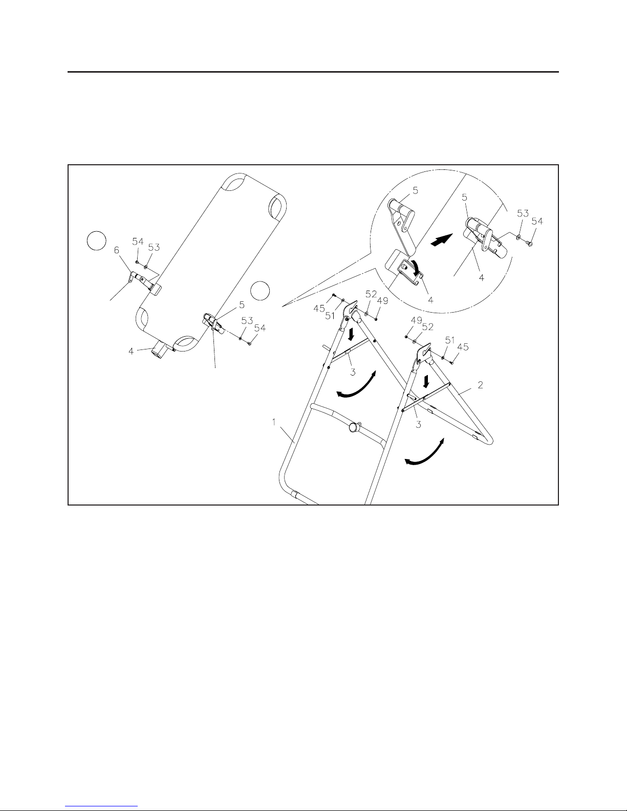
STEP 1
Unf old the BASE ASSEMBL Y to an upright position by moving the FRONT FRAME(1) away from REAR
FRAME(2). Then push down on the middle of the two FOLDING LINKAGES(3) until they are fully
locked down.
STEP 2
There is a "L" decal on the LEFT PIVOT ARM(5), and a "R" decal on the RIGHT PIVOT ARM(6).
Slide the bottom of the LEFT and RIGHT PIVOT ARMS(5, 6) into the bra ckets located at ea ch side of the
MAIN FRAME(4). Align the hole on the arm with the peg on the bracket, and insert the peg into the hole
to lock the
PIVOT ARMS(5, 6) in position. Then secure the PIVOT ARMS(5, 6) on the pegs with
BUTTON HEAD BOLTS(M6 x 8mm)(54) and LARGE W ASHERS(M6)(53).
STEP 3
Attach the MAIN FRAME(4) onto the REAR FRAME(2) by sliding the slots in the ends of the PIVOT
ARMS(5, 6) into the slots on the REAR FRAME(2). Secure the PIVOT ARMS(5, 6) in the slots by
screwing the
BOLTS(M8 x 15mm)(45), WASHERS(M8)(51), LARGE WASHERS(M8)(52), and
NYLOCK NUTS(M8)(49) onto the brackets on the REAR FRAME(2).
R
L
 Loading...