

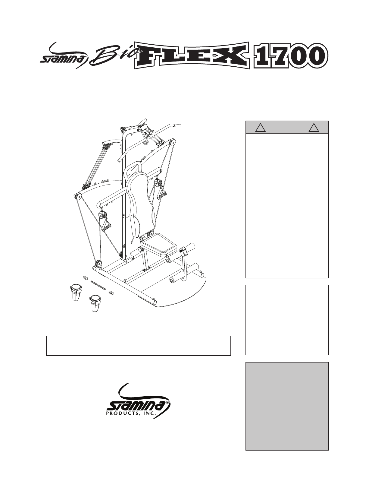
Stamina BioFLEX 1700, BioFlex 2200, 50-0220, 50-0170 Owner's Manual
When calling for parts or
service, please specify
the following number
:
Model#: 50-0170
CAUTION:
Weight on this product should not exceed 250 lbs.
Owner's Manual
This Product is Produced Exclusively by
2040 N. Alliance, Springeld, MO 65803
Customer Service
1 (800) 375-7520
www.staminaproducts.com
Product May Vary Slightly From Pictured.
!
WARNING
!
Exercise can present a
health risk. Consult a
physician before beginning
any exercise program with
this equipment. If you feel
faint or dizzy, immediately
discontinue use of this
equipment. Serious bodily
injury can occur if this
equipment is not assembled
and used correctly. Serious
bodily injury can also occur
if all instructions are not
followed. Keep others and
pets away from equipment
when in use. Always make
sure all bolts and nuts are
securely tightened prior to
each use. Follow all safety
instructions in this manual.
STAMINA PRODUCTS
MADE IN CHINA
©
2009 Stamina Products, Inc.
2009, 09

TABLE OF CONTENTS
Safety Instructions ...................................... 2
Before You Begin ........................................ 4
Equipment Warning & Notice Labels ........ 5
Hardware Identication Chart .................... 6
Assembly Instructions ................................ 7
Setting Up The Accessories...................... 14
Conditioning Guidelines ........................... 15
Warm-Up and Cool-Down ......................... 16
Operational Instructions ........................... 17
Training Tips & Workout Instructions ...... 18
Storage & Maintenance ............................. 23
Product Parts Drawing .............................. 24
Parts List .................................................... 25
Warranty ..................................................... 27
Notes ........................................................... 28
Fax/Mail Ordering Form ............................ 30
SAFETY INSTRUCTIONS
2
1. Read all warnings posted on the BioFLEX 1700.
2. The BioFLEX 1700 should only be used after a thorough review of the Owner’s Manual.
3. We recommend that two people be available for assembly of this product.
4. Keep children away from the BioFLEX 1700. Do not allow children to use or play on the
BioFLEX1700. Keep children and pets away from the BioFLEX 1700 when it is in use.
5. It is recommended that you place this exercise equipment on an equipment mat.
6. Set up and operate the BioFLEX 1700 on a solid level surface. Do not position the BioFLEX
1700 on loose rugs or uneven surfaces.
7. Make sure that adequate space is available for access to and around the BioFLEX 1700.
8. Before using, inspect the BioFLEX 1700 for worn or loose components, and securely tighten or
replace any worn or loose components prior to use.
9. Prior to each use, check the condition of the Cables. Replace the Cables if the plastic coatings
are cracked or broken.
10. Prior to each use, verify that the Cables are properly installed on the Pulleys.
11. Prior to each use, check the Bungee Cords for wear. Replace Bungee Cords that are frayed or
worn.
12. Prior to each use, check the plastic hooks on the both ends of all Bungee Cords and replace any
Bungee Cords that have damaged hooks.
13. Prior to each use, check the Pulleys for excessive wear. Replace worn Pulleys.
14. Consult a physician prior to commencing an exercise program and follow his/her
recommendations in developing your tness program. If at any time during exercise you feel faint,
dizzy, or experience pain, stop and consult your physician.
15. Follow your physician’s recommendations in developing your own personal tness program.
16. Always choose the workout which best ts your physical strength and exibility level. Know your
limits and train within them. Always use common sense when exercising.
17. Do not wear loose or dangling clothing while using the BioFLEX 1700.
18. Never exercise in bare feet or socks; always wear proper footwear such as running, walking, or
cross training shoes that t well, provide foot support, and feature non-skid rubber soles.
19. Be careful to maintain your balance while using, mounting, dismounting, or assembling the
BioFLEX, loss of balance may result in a fall and serious bodily injury.
20. The BioFLEX 1700 should not be used by persons weighing over 250 pounds.
21. The BioFLEX 1700 should be used by only one person at a time.
22. The BioFLEX 1700 is for consumer use only. It is not for use in public or semipublic facilities.
!
WARNING: To reduce the risk of serious injury, read the following Safety Instructions
before using the BioFLEX 1700.
WARNING: Before starting any exercise or conditioning program you should consult with your personal physician
to see if you require a complete physical exam. This is especially important if you are over the age of 35, have never
exercised before, are pregnant, or suffer from any illness.
READ AND FOLLOW THE SAFETY PRECAUTIONS.
FAILURE TO FOLLOW THESE INSTRUCTIONS CAN RESULT IN SERIOUS BODILY INJURY.
!

THANK YOU FOR PURCHASING THE
BioFLEX 1700
Your BioFLEX 1700 does require assembly.
Please follow the assembly steps set forth in this manual.
With regular workouts, you will be getting your body into shape
and be on your way to achieving a happier and healthier lifestyle.
Should you have any questions,
please call our Customer Service Department toll-free number,
1 (800) 375-7520
Monday - Thursday, 7:30 A.M. - 5:00 P.M., Central Time.
Friday, 8:00 A.M. - 3:00 P.M., Central Time.
TELEPHONE
CUSTOMER SERVICE
Tel: 1 (800) 375-7520
FAX
CUSTOMER SERVICE
Fax: (417) 889-8064
MAIL
STAMINA PRODUCTS, INC.
ATTN: Customer Service
P.O. Box 1071
Springeld, MO. 65801-1071
ONLINE
CUSTOMER SERVICE
customerservice@staminaproducts.com
www.staminaproducts.com
3
Call Us First
www.staminaproducts.com
1 (800) 375-7520
Customer Service
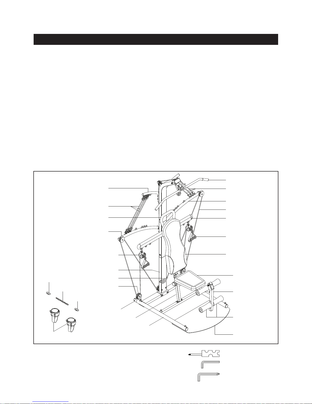
Base Frame
Pulley Set
Ankle Cuff
Crossing Bar
Lat Bar
Left Force Arm
Tension Cords
Tension Post
Right Force Arm
Tension Cords
Chain
Hand Strap
Front Support
Cable
Wheel
Handrail
Thank you for choosing the BioFLEX 1700. We
take great pride in producing this quality product
and hope it will provide many hours of quality
exercise to make you feel better, look better, and
enjoy life to its fullest.
It's a proven fact that a regular exercise program
can improve your physical and mental health.
Too often, our busy lifestyles limit our time and
opportunity to exercise. The BioFLEX 1700
provides a convenient and simple method to begin
your assault on getting your body in shape and
achieving a happier and healthier lifestyle.
Before reading further, please review the
drawing below and familiarize yourself with the
parts that are labeled.
Read this manual carefully before using the
BioFLEX 1700.
BEFORE YOU BEGIN
Although Stamina constructs its products with
the nest materials and uses the highest standards
of manufacturing and quality control, there can
sometimes be missing parts or incorrectly sized
parts. If you have any questions or problems with
the parts included with your BioFLEX 1700, please
do not return the product. Contact us FIRST!
If a part is missing or defective, please call
us toll free at 1-800-375-7520 (in the U.S.). Our
Customer Service Staff is available to assist you
from 7:30 A.M. to 5:00 P.M. (Central Time) Monday
through Thursday and 8:00 A.M. to 3:00 P.M.
(Central Time) on Friday.
If you would like to contact us online, go to our
website at www.staminaproducts.com and access
the Customer Service section.
Be sure to have the name and model number of
the product available when you contact us.
4
Leg Lift
Back Cushion
Seat
Foam Pads
Lower Upright
Warning Label
Pulley Set
Quick Link
Base Plate
Quick
Link
THE FOLLOWING TOOLS ARE INCLUDED FOR ASSEMBLY : Combination Wrench
Allen Wrench (5mm)
Allen Wrench (6mm)
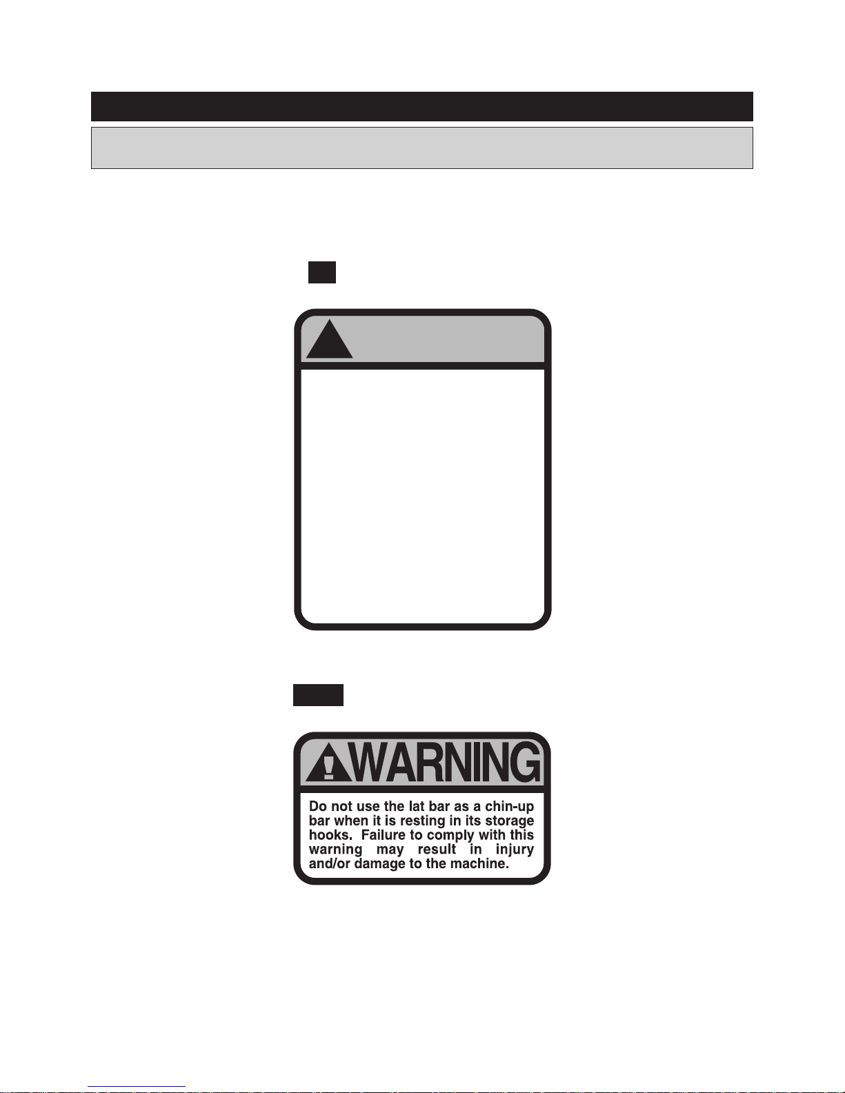
Label is larger than actual size
EQUIPMENT WARNING & NOTICE LABELS
WARNING LABEL(72)W1
5
WARNING
!
BEFORE BEGINNING THIS OR ANY EXERCISE
PROGRAM, CONSULT YOUR PHYSICIAN. THIS IS
ESPECIALLY IMPORTANT FOR PERSONS OVER
THE AGE OF THIRTY-FIVE OR WITH
PREEXISTING HEALTH PROBLEMS. STAMINA®
ASSUMES NO RESPONSIBILITY FOR PERSONAL
INJURY OR PROPERTY DAMAGE SUSTAINED BY
OR THROUGH THE USE OF THIS PRODUCT.
Make sure all nuts and bolts are securely tightened, and
follow all safety tips and instructions set forth herein. This
product should not be used by persons weighing more than
250 lbs. unless otherwise stated in the front of your manual.
Keep others including children & pets
away from equipment when in use.
Failure to comply with these warnings could
result in serious injury or death. All warnings
and instructions are to be read prior to use.
Replace this warning label if damaged,
illegible, or removed.
LAT BAR WARNING LABEL(73)W2
This chart is provided to help identify the warning & notice labels on the BioFLEX 1700. Please take
a moment to familiarize yourself with all of the warning & notice labels.
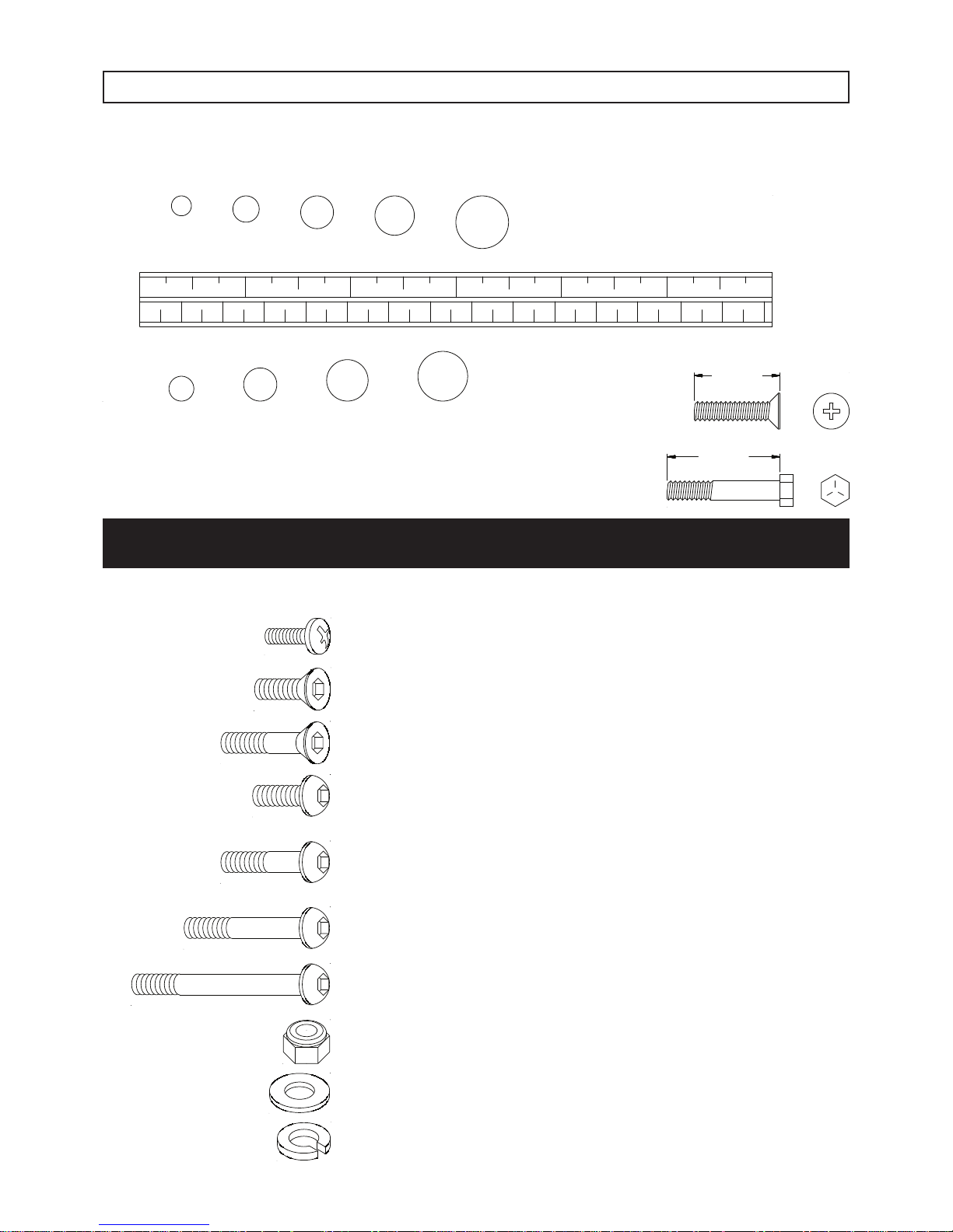
53 Bolt, Flat Head (M8 x 1.25 x 20mm) 5
59 Bolt, Button Head (M8 x 1.25 x 115mm) 1
64 Bolt, Button Head (M10 x 1.5 x 105mm) 2
65 Bolt, Button Head (M10 x 1.5 x 110mm) 2
69 Washer (M8) 16
70 Washer (M10) 29
71 Lock Washer (M10) 6
Part Number and Description Qty
67 Nylock Nut (M8 x 1.25) 8
68 Nylock Nut (M10 x 1.5) 7
This chart is provided to help identify the hardware used in the assembly process. Place the washers or
the ends of the bolts or screws on the circles to check for the correct diameter. Use the small scale to
check the length of the bolts and screws.
NOTICE: The length of all bolts and screws, except those with flat
heads, is measured from below the head to the end of the bolt
or screw. Flat head bolts and screws are measured from the
top of the head to the end of the bolt or screw.
length
length
After unpacking the unit, open the hardware bag and make sure that you have all the following items.
Some hardware may be already attached to the part.
56 Bolt, Button Head (M8 x 1.25 x 45mm) 1
61 Bolt, Button Head (M10 x 1.5 x 50mm) 4
62 Bolt, Button Head (M10 x 1.5 x 60mm) 2
63 Bolt, Button Head (M10 x 1.5 x 65mm) 1
HARDWARE IDENTIFICATION CHART
6
mm.
in.
INCHES
MILLIMETERS
0 10 20 30 40 50 60 70 80 90 100 110 120 130 140 150
0 1/2 1 1/2 2 1/2 3 1/2 4 1/2 5 1/2 6
6 8 10 12
3/16" 1/4" 5/16" 3/8" 1/2"
52 Bolt, Round Head (M6 x 1 x 15mm) 8
55 Bolt, Button Head (M8 x 1.25 x 15mm) 4
60 Bolt, Button Head (M10 x 1.5 x 15mm) 10
57 Bolt, Button Head (M8 x 1.25 x 80mm) 2
58 Bolt, Button Head (M8 x 1.25 x 90mm) 2
54 Bolt, Flat Head (M8 x 1.25 x 50mm) 2
Place all parts from the box in a cleared area and position them on the oor in front of you. Remove
all packing materials from your area and place them back into the box. Do not dispose of the
packing materials until assembly is completed. Read each step carefully before beginning. If you
are missing a part please call our toll-free number for assistance 1-800-375-7520 or e-mail us at
customerservice@staminaproducts.com.
ASSEMBLY INSTRUCTIONS
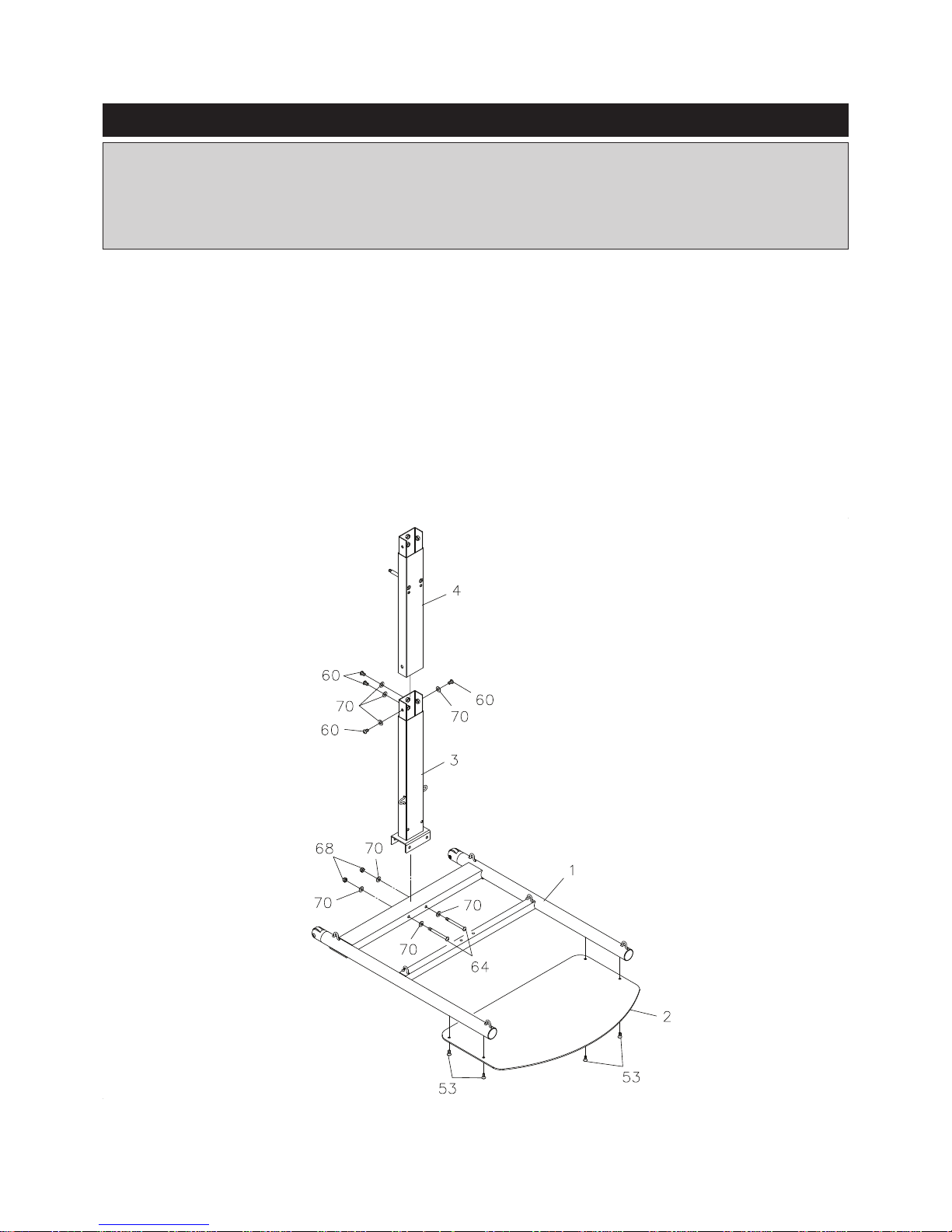
STEP 1
Attach the BASE PLATE(2) to the BASE FRAME(1) with FLAT HEAD BOLTS(M8x1.25x20mm)(53).
STEP 2
Attach the LOW E R UPR I G H T(3) to the BASE FRAM E ( 1 ) with BUTTON HEAD BOLTS
(M10x1.5x105mm)(64), WASHERS(M10)(70), and NYLOCK NUTS(M10x1.5)(68).
STEP 3
Attach the UPRIGHT(4) to the LOWER UPRIGHT(3) with BUTTON HEAD BOLTS(M10x1.5x15mm)(60)
and WASHERS(M10)(70).
7
ASSEMBLY INSTRUCTIONS
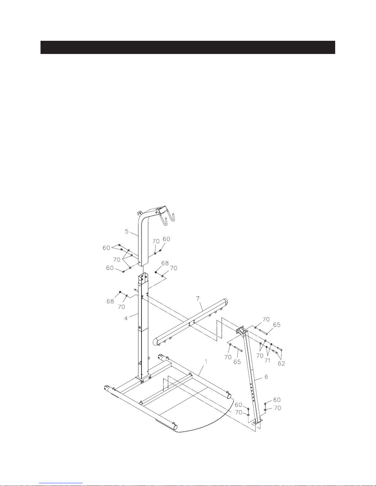
STEP 4
Attach the TOP BEAM(5) to the UPRIGHT(4) with BUTTON HEAD BOLTS(M10x1.5x15mm)(60) and
WASHERS(M10)(70).
STEP 5
Attach the CROSSING BAR(7) and FRONT SUPPORT(6) to the UPRIGHT(4) with BUTTON HEAD
BOLT S(M1 0x1. 5x110m m)(6 5), WA SHER S(M1 0)(7 0), NYLO CK N UTS( M10x 1.5) (68), LOCK
WASHERS(M10)(71), and BUTTON HEAD BOLTS(M10x1.5x60mm)(62). Do not tighten the bolts.
STEP 6
Attach the FRONT SUPPORT(6) to the BASE FRAME(1) with BUTTON HEAD BOLTS(M10x1.5x15mm)
(60) and WASHERS(M10)(70). Securely tighten all of the bolts from STEP 5.
8
ASSEMBLY INSTRUCTIONS
9
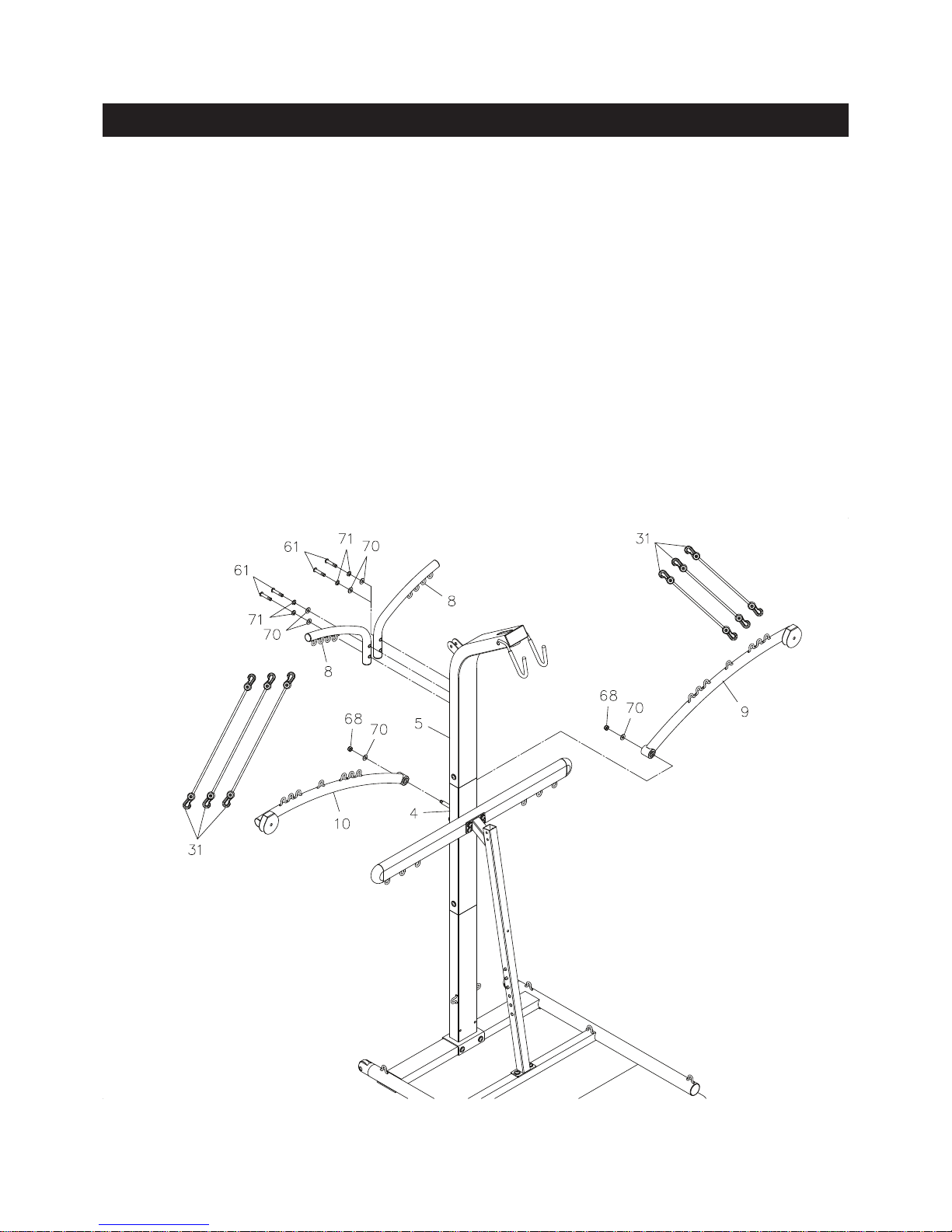
STEP 7
Attach the TENSION POSTS(8) to the back of the TOP BEAM(5) with BUTTON HEAD BOLTS
(M10x1.5x50mm)(61), LOCK WASHERS(M10)(71) and WASHERS(M10)(70).
STEP 8
Slide the LEFT and RIGHT FORCE ARMS(9, 10) onto the shafts on UPRIGHT(4) and secure with
WASHERS(M10)(70) and NYLOCK NUTS(M10x1.5)(68). Do not over tighten the nuts, as the LEFT and
RIGHT FORCE ARMS(9, 10) must be able to pivot smoothly.
STEP 9
Hook three TENSION CORDS(31) to the three hooks at the top of the TENSION POSTS(8) on both
sides. Hook the lower ends of the TENSION CORDS(31) to the hooks on outer ends of the LEFT and
RIGHT FORCE ARMS(9, 10) on both sides.
 Loading...