

Page 1
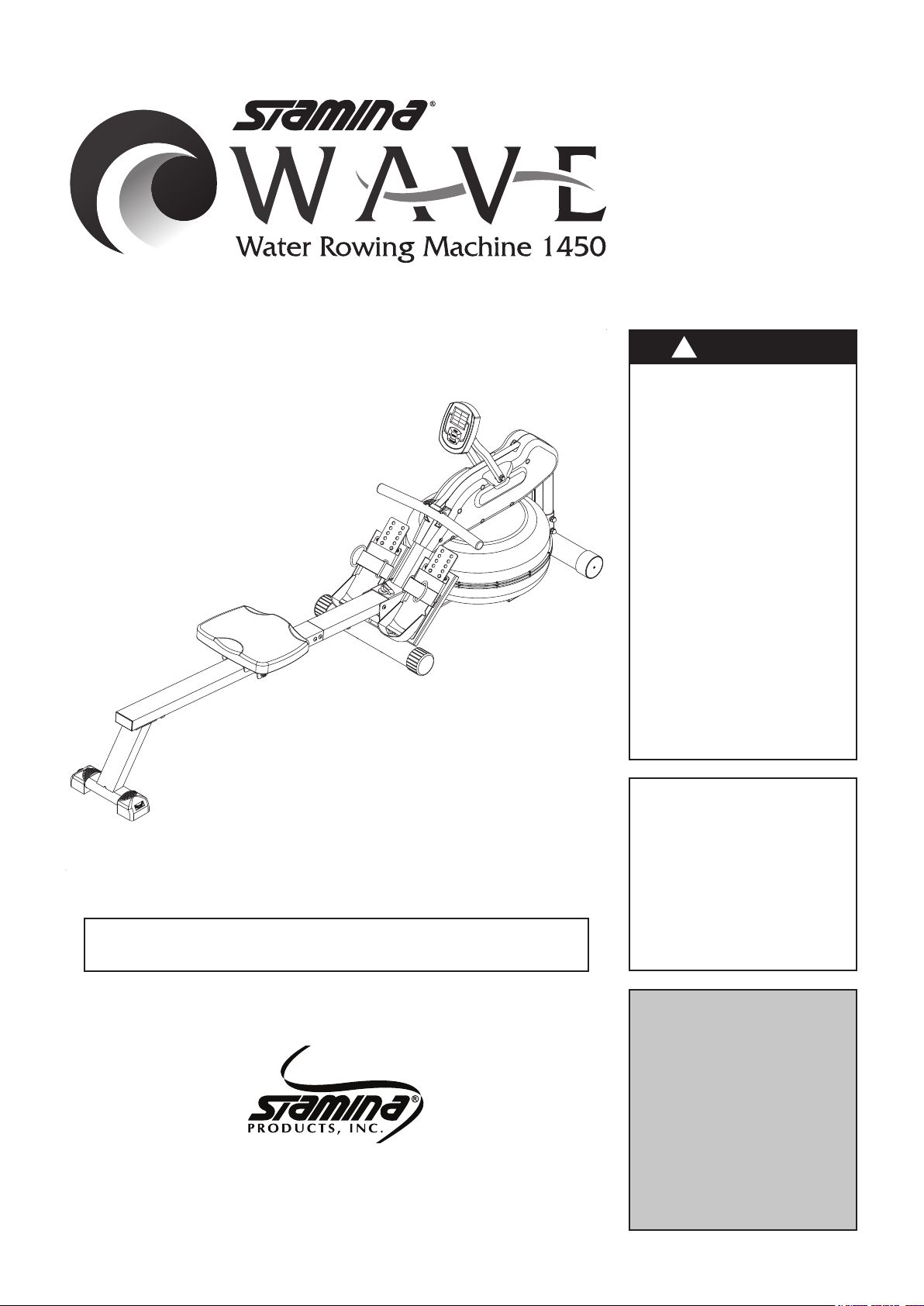
Owner's
Manual
!
WARNING
Exercise can present a
health risk. Consult a
physician before beginning
any exercise program with
this equipment. If you feel
faint or dizzy, immediately
discontinue use of this
equipment. Serious bodily
injury can occur if this
equipment is not assembled
and used correctly. Serious
bodily injury can also occur
if all instructions are not
followed. Keep others and
pets away from equipment
when in use. Always make
sure all bolts and nuts are
securely tightened prior to
each use. Follow all safety
instructions in this manual.
Product May Vary Slightly From Pictured.
CAUTION:
Weight on this product should not exceed 300 lbs.
This Product is Distributed Exclusively by
2040 N. Alliance, Springeld, MO 65803
Customer Care
1 (800) 375-7520
www.staminaproducts.com
When calling for parts or
service, please specify
the following number
:
Model#: 35-1450
STAMINA PRODUCTS
MADE IN CHINA
2016 Stamina Products, Inc.
©
2017, 07
Page 2

TABLE OF CONTENTS
Safety Instructions ...................................... 2
Before You Begin ........................................ 4
Equipment Warning, Caution & Notice Labels ... 5
Hardware Identication Chart .................... 6
Assembly Instructions ................................ 7
Operational Instructions ............................. 9
Storage ....................................................... 15
Maintenance ............................................... 15
Trouble Shooting Guide ............................ 16
Conditioning Guidelines ........................... 20
Warm-Up and Cool-Down ......................... 21
Product Parts Drawing .............................. 22
Parts List .................................................... 23
Warranty ..................................................... 25
Notes .......................................................... 26
Fax/Mail Ordering Form ............................ 27
SAFETY INSTRUCTIONS
WARNING
!
WARNING
!
WARNING
!
1. Save these instructions and ensure that other exercisers read this manual prior to using the Wave
Water Rowing Machine 1450 for the rst time.
2. Read all warnings and cautions posted on the Wave Water Rowing Machine 1450.
3. The Wave Water Rowing Machine 1450 should only be used after a thorough review of the Owner’s
Manual. Make sure that it is properly assembled and tightened before use.
4. We recommend that two people be available for assembly of this product.
5. Keep children away from the Wave Water Rowing Machine 1450. Do not allow children to use or
play on the Wave Water Rowing Machine 1450. Keep children and pets away from the Wave Water
Rowing Machine 1450 when it is in use.
6. It is recommended that you place this exercise equipment on an equipment mat.
7. Set up and operate the Wave Water Rowing Machine 1450 on a solid level surface. Do not position
the Wave Water Rowing Machine 1450 on loose rugs or uneven surfaces.
8. Make sure that adequate space is available for access to and around the Wave Water Rowing
Machine 1450.
9. Before using, inspect the Wave Water Rowing Machine 1450 for worn or loose components, and
securely tighten or replace any worn or loose components prior to use.
10. Before using, always check the RAIL(3) to be sure it is securely tighten with the FIXING LEVER(46)
and LARGER WASHER(9).
11. Consult a physician prior to commencing an exercise program and follow his/her recommendations
in developing your tness program. If at any time during exercise you feel faint, dizzy, or experience
pain, stop and consult your physician.
12. Follow your physician’s recommendations in developing your own personal tness program.
13. Always choose the workout which best ts your physical strength and exibility level. Know your
limits and train within them. Always use common sense when exercising.
14. Do not wear loose or dangling clothing while using the Wave Water Rowing Machine 1450.
15. Never exercise in bare feet or socks; always wear proper footwear such as running, walking, or cross
training shoes that t well, provide foot support, and feature non-skid rubber soles.
16. Be careful to maintain your balance while using, mounting, dismounting, or assembling the Wave
Water Rowing Machine 1450, loss of balance may result in a fall and serious bodily injury.
17. The Wave Water Rowing Machine 1450 should not be used by persons weighing over 300 pounds.
18. The Wave Water Rowing Machine 1450 should be used by only one person at a time.
19. The Wave Water Rowing Machine 1450 is for consumer use only. It is not for use in public or
semipublic facilities.
Cancer and Reproductive Harm www.P65Warnings.ca.gov
Consult your physician before starting this or any exercise program. This is
especially important if you are over the age of 35, have never exercised before,
are pregnant, or suer from any health problem. This product is for home use
only. Do not use in institutional or commercial applications. Failure to follow all
warnings and instructions could result in serious injury or death.
To reduce the risk of serious injury, read the following Safety Instructions
before using the
Wave Water Rowing Machine 1450
2
.
Page 3

NEED HELP?
CONTACT US FIRST
1 (800) 375-7520
customer.care@staminaproducts.com
Hi! From all of us here at Stamina Products, thank you for your purchase. We
know that you have big fitness goals in mind and we are here to help you along.
Call us, email us, or send us a message on Facebook. Be sure to contact us if you
have any questions on your new product. We look forward to hearing from you!
With your body in mind,
Stamina Customer Care
To enact your extended warranty and to help us better
serve you, please go online and register your new product.
register.staminaproducts.com
It is quick and easy to register online, but if you’re a little old school or just need a
reason to raise that little flag on your mailbox, fill out the info on the last page of this
manual and mail it in.
customer.care@staminaproducts.com
ONLINE
www.staminaproducts.com
facebook.com/StaminaProducts
facebook.com/AeroPilates
TELEPHONE
1 (800) 375-7520
FAX
(417) 889-8064
Springfield, MO 65801-1071
CUSTOMER CARE HOURS:
Monday-Thursday, 7:30 AM-5:00 PM, Central Time
Friday, 8:00 AM-3:00 PM, Central Time
MAIL
Stamina Products, Inc.
ATTN: Customer Care
P.O. Box 1071
Page 4

BEFORE YOU BEGIN
Thank you for choosing the Wave Water
Rowing Machine 1450. We take great pride in
producing this quality product and hope it will
provide many hours of quality exercise to make
you feel better, look better, and enjoy life to its
fullest.
It's a proven fact that a regular exercise program
can improve your physical and mental health.
Too often, our busy lifestyles limit our time and
opportunity to exercise. The Wave Water Rowing
Machine 1450 provides a convenient and simple
method to begin your journey of getting your body
in shape and achieving a happier and healthier
lifestyle.
Before reading further, please review the
drawing below and familiarize yourself with the
parts that are labeled.
Read this manual carefully before using the
Wave Water Rowing Machine 1450.
Although Stamina constructs its products with
the nest materials and uses the highest standards
of manufacturing and quality control, there can
sometimes be missing parts or incorrectly sized
parts. If you have any questions or problems with
the parts included with your Wave Water Rowing
Machine 1450, please do not return the product.
Contact us FIRST!
If a part is missing or defective, please go to
staminaproducts.com under the Customer Care
section and order the part needed, or call us toll
free at 1-800-375-7520 (in the U.S.). Our Customer
Care Staff is available to assist you from 7:30
A.M. to 5:00 P.M. (Central Time) Monday through
Thursday and 8:00 A.M. to 3:00 P.M. (Central
Time) on Friday.
Be sure to have the name and model number of
the product available when you contact us.
Long Rail
Fixing Lever
Short Rail
Seat
Strap
Handlebar
Pedal Cap
Adjustable Endcap
Meter
Meter Post
Right Cover
Main Frame
Upper Tank
Base Frame
Wheel Endcap
Lower Tank
Pedal Strap
Pedal Cap
Round Endcap
Caution Label
Seat CarriageRear Stand
THE FOLLOWING TOOLS ARE INCLUDED FOR ASSEMBLY : Allen Wrench (5mm)
Allen Wrench (6mm)
Combination Wrench
4
Page 5
EQUIPMENT WARNING, CAUTION & NOTICE LABELS
CAUTION
This chart is provided to help identify the warning, caution, and notice labels on the Wave Water
Rowing Machine 1450. Please take a moment to familiarize yourself with all of the warning, caution,
and notice labels.
Label is larger than actual size
CAUTION LABEL(94)C1
!
For consumer use only. Failure to follow all warnings
and instructions could result in injury or property
damage. Before assembling or using this product, read
and follow the Owner’s Manual and all other warnings
and instructions that accompany this product. Replace
this caution label if damaged, illegible, or removed.
Keep others including children & pets
away from equipment when in use.
Consult your physician before starting this or any exercise
program. This is especially important if you are over the
age of 35 or have any pre-existing health condition.
Always make sure all nuts and bolts are securely tightened
before using this product. This product should not be used
by person weighing more than 250 lbs. unless otherwise
stated in your Owner’s Manual.
5
Page 6
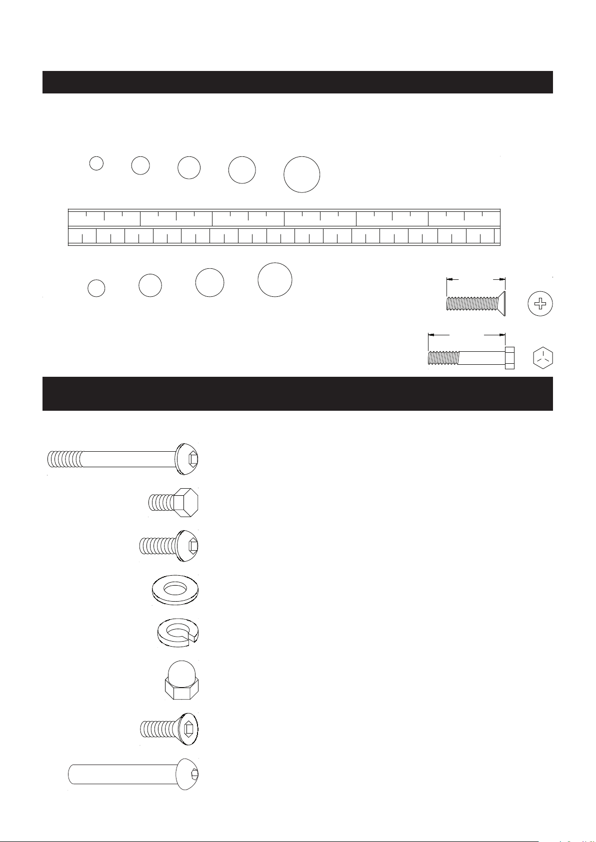
HARDWARE IDENTIFICATION CHART
This chart is provided to help identify the hardware used in the assembly process. Place the washers or
the ends of the bolts or screws on the circles to check for the correct diameter. Use the small scale to
check the length of the bolts and screws.
3/16"
1/4" 5/16" 3/8" 1/2"
INCHES
0 1/2
1 1/2 2 1/2 3 1/2 4 1/2 5 1/2 6
in.
mm.
0 10 20 30 40 50 60 70 80 90 100 110 120 130 140 150
length
6 8
10 12
MILLIMETERS
NOTICE: The length of all bolts and screws, except those with flat
heads, is measured from below the head to the end of the bolt
length
or screw. Flat head bolts and screws are measured from the
top of the head to the end of the bolt or screw.
After unpacking the unit, open the hardware bag and make sure that you have all the following items.
Some hardware may be already attached to the part.
Part Number and Description Qty
64 Bolt, Button Head (M8 x 1.25 x 130mm) 1
69 Bolt, Hex Head (M8 x 1.25 x 15mm) 4
71 Bolt, Button Head (M6 x 1 x 15mm) 1
76 Bolt, Button Head (M8 x 1.25 x 15mm) 4
9 Larger Washer
(ø10.5mm x ø40mm x 3mm thick)
1
78 Washer (M8) 5
81 Lock Washer (M8) 1
83 Acorn Nut (M8 x 1.25) 1
90 Bolt, Flat Socket Head (M8 x 1.25 x 15mm) 4
98 Barrel Nut (M8 x 1.25 x 88mm) 1
6
Page 7
ASSEMBLY INSTRUCTIONS
Place all parts from the box in a cleared area and position them on the oor in front of you. Remove
all packing materials from your area and place them back into the box. Do not dispose of the packing
materials until assembly is completed. Read each step carefully before beginning. If you are missing
a part, please go to staminaproducts.com under the Customer Care section and order the part
needed, e-mail us at customer.care@staminaproducts.com, or call us toll free at 1-800-375-7520
(in the U.S.). Our Customer Care Sta is available to assist you from 7:30 A.M. to 5:00 P.M. (Central
Time) Monday through Thursday and 8:00 A.M. to 3:00 P.M. (Central Time) on Friday.
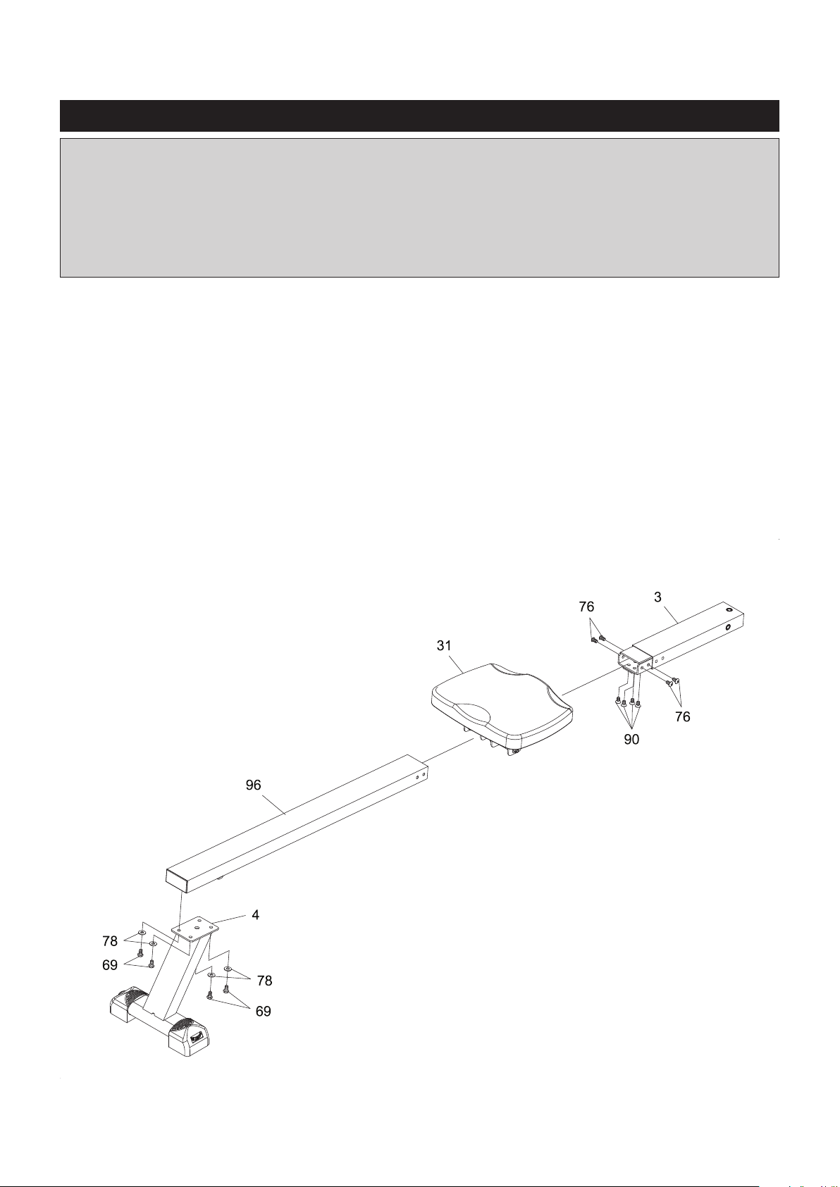
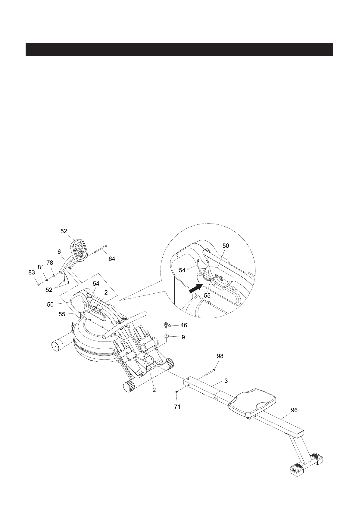
STEP 1
Attach the REAR STAND(4) to the LONG RAIL(96) with HEX HEAD BOLTS(M8x1.25x15mm)(69) and
WASHERS(M8)(78).
STEP 2
Slide the SEAT(31) onto the LONG RAIL(96). Insert the SHORT RAIL(3) into the LONG RAIL(96), then secure
with BUTTON HEAD BOLTS(M8x1.25x15mm)(76) and FLAT SOCKET HEAD BOLTS(M8x1.25x15mm)
(90).
7
Page 8
ASSEMBLY INSTRUCTIONS
STEP 3
Attach the SHORT RAIL(3) to the MAIN FRAME(2) with BUTTON HEAD BOLT(M6x1x15mm)(71) and
BARREL NUT(M8x1.25x88mm)(98). Lock the RAIL(3) in unfold position with the FIXING LEVER(46) and
LARGER WASHER(ø10.5mmxø40mmx3mm thick)(9).
NOTE: After tightening the FIXING LEVER(46) the rear stabilizer of the BASE FRAME(1) might be raised
o the oor slightly, this is normal, it will rest on the oor once you are seated.
STEP 4
Install two AA batteries into the METER(52), the batteries are not included. See page 13 for detailed
battery installation instructions. Attach the METER POST(6) to the MAIN FRAME(2) with BUTTON HEAD
BOLT(M8x1.25x130mm)(64), WASHER(M8)(78), LOCK WASHER(M8)(81), and ACORN NUT(M8x1.25)
(83).
STEP 5
Refer to the detail view. Clip the GROMMET(55) onto both SENSOR WIRES(54), then press the
GROMMET(55) into the LEFT COVER(50). Connect the SENSOR WIRES(54) to the CONNECTION WIRES
of the METER(52). Push the excess wires back into the LEFT COVER(50).
8
Page 9
OPERATIONAL INSTRUCTIONS
HEART RATE TRANSMITTER
The Wave Water Rowing Machine 1450 can measure how hard you are exercising by monitoring your
heart rate with the HEART RATE TRANSMITTER(102). Your heart rate reading gives you a snapshot of how
hard your heart is working at that point in your workout by measuring the number of heart beats per minute.
The HEART RATE TRANSMITTER(102) worn around your chest sends your heart rate information to a
receiver inside the METER(52) so your heart rate is tracked while you exercise. This is the most reliable
way to measure your heart rate to make sure you are exercising within your target heart rate zone so you
get the most out of your workout time.
Using the Heart Rate Transmitter Chest Strap
The HEART RATE TRANSMITTER(102) worn around the chest is powered by a BUTTON BATTERY
(CR2032)(106) located in the back of the HEART RATE TRANSMITTER(102). Two electrodes on ELASTIC
SENSOR STRAP(103) monitor your heartbeat, and the adjustable ELASTIC SENSOR STRAP(103) holds
the transmitter in place. The receiver built into the Wave Water Rowing Machine 1450 picks up your heart
rate from the HEART RATE TRANSMITTER(102) and displays it on the monitor during your workout.
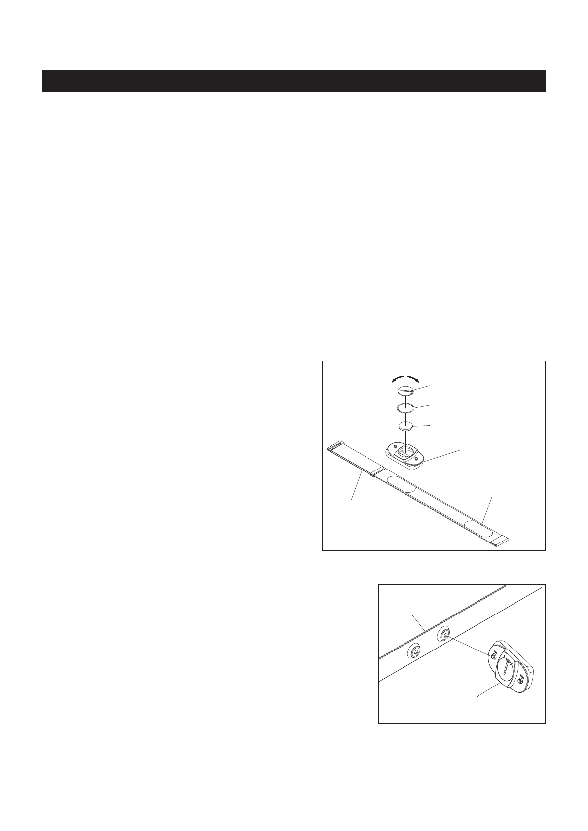
To assemble the HEART RATE TRANSMITTER(102),
insert the BUTTON BATTERY(CR2032)(106) as shown
in the illustration. Place the BATTERY RUBBER
RING(104) on the edge of the opening and place
the BATTERY COVER(105) over the BUTTON
BATTERY(CR2032)(106). Using a coin or similar object,
press down on the BATTERY COVER(105) and turn
to securely close the cover.
NOTE:
1. Make sure to close the BATTERY COVER
(105) very tightly as illustrated to prevent
sweat and moisture from damaging the
battery.
2. The HEART RATE TRANSMITTER(102) is
(103) Elastic
Sensor Strap
latex free and its material is appropriate for
human contact.
Refer to the illustration. Press the HEART RATE TRANSMITTER(102)
onto the buttons on the ELASTIC SENSOR STRAP(103).
open
(103) Elastic
Sensor Strap
close
(105) Battery Cover
(104) Battery Rubber Ring
(106) Button Battery
(102) Heart Rate Transmitter
Heart Rate
Sensor Electrode
(102) Heart Rate Transmitter
9
Page 10

OPERATIONAL INSTRUCTIONS
To wear the HEART RATE TRANSMITTER(102) around the chest, hook the hook end of the ELASTIC
SENSOR STRAP(103) to the other end of the ELASTIC SENSOR STRAP(103). Adjust the ELASTIC
SENSOR STRAP(103) to t your chest snugly as shown in the illustration below. Apply water or conductive
gel to moisten the heart rate sensor electrodes. These heart rate sensor electrodes must be wet and in
contact with your chest skin to properly detect your heart rate.
(103)Elastic Sensor Strap(103)Elastic Sensor Strap
Hook
NOTE: If your heart rate is inconsistent or not tracking on your workout monitor, do the following:
The HEART RATE TRANSMITTER(102) will connect to the monitor while using the unit and
within close proximity of the unit. If you are too far from the unit the connection will be lost.
Moisten the heart rate sensor electrodes on the back of the ELASTIC SENSOR STRAP(103)
and make sure they are in contact with the skin. Your skin may be dry when you begin your
workout and the moisture is necessary to ensure contact. As you sweat, contact will improve.
Tighten the elastic strap so it remains in place as you exercise. Movement of the heart rate sensor
electrodes will result in inaccurate or erratic signal and readings.
Clean the heart rate sensor electrodes as dirt can interfere with transmission. Use a mild soap
and water and dry with a soft towel.
Transmitter Care and Maintenance
Wash regularly with mild soap and water solution and dry with a soft towel being careful not to scratch
the heart rate sensor electrodes.
Store in a cool, dry place. Make sure the heart rate sensor electrodes aren’t stored with any wet material
and never store a wet transmitter in non-breathable material like a plastic bag or sports bag.
Do not stretch the heart rate sensor electrodes.
NOTE: The frequency of the receiver built into the Wave Water Rowing Machine 1450 is 5 kHz. All
compatible heart rate transmitters from other companies will work with the Wave Water Rowing
Machine 1450.
10
Page 11

OPERATIONAL INSTRUCTIONS
USING THE FITNESS METER
POWER ON:
POWER OFF:
Handlebar movement or press any button.
Automatically shuts off after 4 minutes of
inactivity.
FUNCTION BUTTONS :
MODE : Press and release to select each function for
preset target values for TIME, COUNT, DISTANCE,
CALORIES, and PULSE.
RESET :
(UP):
(DOWN):
RECOVERY: Press to activate the pulse recovery function after training. You must wear the HEART RATE
In the setting mode, press the button to reset the
setting values to zero for TIME, COUNT, DIS-
TANCE, and CALORIES. And reset the setting
value of PULSE to 90.
Press the button and hold it down for two seconds
to reset all functions to zero.
Press to increase the values of the setting mode.
Press to decrease the values of the setting mode.
TRANSMITTER(102) around your chest to measure your heart rate.
FUNCTIONS:
TIME:
COUNT
DISTANCE:
CALORIES:
STROKES/MIN:
PULSE:
:
Displays the time from 1 sec. up to 99:59 minutes. Counts down from preset value.
Displays the total number of rows you have taken from zero to 9999.
Displays distance from zero to 99.9 Kilometers. Counts down from preset value.
Displays the calorie burned from zero to 9999 Kcal. Counts down from preset value.
The calorie readout is an estimate for an average user. It should be used only as a
comparison between workouts on this unit.
Displays the rowing speed from zero to 999 strokes per minute.
Displays the heart rate, from 40 to 240 beats per minute.
To use this function, you must wear the HEART RATE TRANSMITTER(102) around your
chest so the receiver which is built into the rower registers your heart rate from the HEART
RATE TRANSMITTER(102) for displaying. Each heart rate signal will be accompanied with
one “
your chest correctly, a “P” mark will be displayed.
You can use UP, DOWN, and RESET buttons to input your target pulse value. When you
are exercising, the meter will remind you with an audible alarm when you reach or exceed
your target pulse value. Slow your exercise intensity gradually to stay within your target
pulse zone.
NOTE: The HEART RATE TRANSMITTER(102) is not a medical device. Maintaining a
consistent signal can be dicult due to the varying distances experienced during the rowing
stroke. The pulse function is a great tool to optimize your workout, but should be used as
a reference only.
“ symbol ash. If you do not wear the HEART RATE TRANSMITTER(102) around
TRAVEL DISTANCE INDICATOR:
Indicates the travel distance on the rower during exercise.
11
Page 12

OPERATIONAL INSTRUCTIONS
PRESET VALUES OPERATION:
You can pull on the HANDLEBAR(8) to power on the meter and workout with the meter directly. Or, you can
preset the function values for counting down. Stop rowing for four seconds, then press the MODE button to
enter setting mode. The meter will go through the input items as follows and allow you to set the function
values. Use UP, DOWN, and RESET buttons to input the values, and press MODE button to conrm. Or,
just press the MODE button to skip the setting and move on to the next function. After all the desired settings
are chosen, begin pulling on the HANDLEBAR(8) to start the workout.
Time (1:00 to 99:00) Count (10 to 9990) Distance (0.1 to 99.9 Km) Calories (1.0 to 9999 Kcal) Pulse (90 to 220 bpm)
NOTE:
1. You may preset values for several functions. The preset function values will start to count down.
When you complete one of the preset functions, the meter will remind you with an audible alarm for
three seconds. Then the value of this completed function will start to count up, while the other preset
functions will continue to count down.
2. The Meter will shut o automatically after 4 minutes of inactivity. All function values will be kept. Press
the RESET button and hold it down for two seconds to reset all functions to zero.
12
Page 13

OPERATIONAL INSTRUCTIONS
PULSE RECOVERY FUNCTION
NOTE: To use this program, you must wear the HEART RATE TRANSMITTER(102) around your chest.
The PULSE RECOVERY function measures how quickly you return to a resting heart rate after exercising.
You can use this function to measure improvement as you get into shape. The meter will monitor your heart
rate for 60 seconds and calculate a Pulse Recovery value from 1 to 6.
1.0 = Excellent 2.0 = Good 3.0 = Fair
4.0 = Below Average 5.0 = Not Good 6.0 = Poor
The readout should only be used as a comparison between workouts. It can be used right after any aerobic
exercise. Stop exercising before starting this function.
To start the pulse recovery function, your heart rate will be displayed approximately ve (5) seconds after
the heart symbol is displayed. Then press the RECOVERY button. During the pulse recovery function, only
PULSE and TIME are working and the display will be as shown in illustration A. TIME will count down from
0:60 and the heart symbol will be blinking. When the TIME reaches 0, the meter will remind you with an
audible alarm for three seconds and show your pulse recovery condition from 1.0 to 6.0. See illustration B.
Press any button to exit the pulse recovery function and skip to Activity Mode.
NOTE:
1. You can press the RECOVERY button at any time to run pulse recovery program, even during
your workout.
2. Once the pulse recovery function starts, the TIME will count down from 60 seconds to zero. You
can press the RESET button to quit the pulse recovery function. If no heart rate signal is available,
a “P” mark will display in PULSE window. And an “E” mark will display in pulse recovery value
window when the TIME reaches 0.
A. B.
Time
The highest
heart rate
detected during
the rst 20
seconds.
Pulse Recovery
Current heart rate
( A "P" mark will be
displayed if a proper
heart rate signal is
unavailable.)
Time
value
HOW TO INSTALL AND REPLACE BATTERIES:
1. Use your nger or a simple tool to pry the cover from the back of
the METER(52).
2. The METER(52) operates with two AA batteries, the batteries
are not included. Refer to the illustration to install or replace the
batteries.
The lowest heart rate
detected during the
Pulse Recovery running.
End heart
rate
AA Batteries
NOTE:
1. Do not mix a new battery with an old battery.
2. Use the same type of battery. Do not mix an alkaline
battery with another type of battery.
3. Rechargeable batteries are not recommended.
4. Ultimate disposal of battery should be handled
according to all state and federal laws and regulations.
5. Do not dispose of batteries in re.
13
Page 14

OPERATIONAL INSTRUCTIONS
HOW TO FILL AND EMPTY THE TANK
1. Remove the FILL PLUG(24) from the UPPER TANK(17).
2. To ll with water, refer to illustration A. Place the FUNNEL(101) into the tank. Use a water cup, or
the SYPHON PUMP(100) and a bucket to ll the tank. Use Water Level Gauge on the side of tank to
measure volume of water in tank to the desired level.
3. To empty tank, refer to illustration B. Place a bucket next to the rower. Use the SYPHON PUMP(100)
to pump out the water from the tank into the bucket.
4. Once completed, insert the FILL PLUG(24) into the UPPER TANK(17). Please wipe excess water
from the frames after lling.
NOTE:
WATER LEVEL
Refer to the detail view of illustration A. The Water Level Gauge is positioned on the side of the tank. The
maximum level to ll the tank is Level 10. DO NOT ll above the Maximum Level - this could void the
warranty. The standard calibration level is Level 9.
The amount of resistance is dictated by the amount of water in the tank. For example Level 3 of water
oer light resistance, Level 9 oers the heaviest resistance.
1. Fill the tank only with municipal water, do not use well water. If municipal water is unavailable,
use distilled water and add a water purication tablet. NEVER USE POOL CHLORINE OR
CHLORINE BLEACH. Refer to the Maintenance section for more advice on water treatment.
2. The water in the tank is not for human or animal consumption. Please safely dispose of the
water after removal from the tank.
A. B.
Water Cup
Water Level Gauge
14
Page 15

STORAGE
1. To store the Wave Water Rowing Machine 1450, simply keep it in a clean dry place.
2. To avoid damage to the electronics, remove the batteries before storing the Wave Water Rowing
Machine 1450 for one year or more.
3. Move the Wave Water Rowing Machine 1450 with the moving wheels on the front of the BASE
FRAME(1). Grasp the REAR STAND(4) to move the Wave Water Rowing Machine 1450. Do not
use the SEAT(31) to move the Wave Water Rowing Machine 1450. The SEAT(31) will move and the
SEAT CARRIAGE(5) may pinch your hand or ngers.
4. Remove water from tank if storing the rower for more than a month without use.
Follow the following process to fold the Wave Water Rowing Machine 1450 as illustrated for easy storage.
5.
a. Remove the FIXING LEVER(46) and LARGER WASHER(9) from the MAIN FRAME(2).
b. Fold the RAILS(3, 96) and lock in the folded position with the FIXING LEVER(46) and LARGER
WASHER(9).
A. B.
MAINTENANCE
The safety and integrity designed into the Wave Water Rowing Machine 1450 can only be maintained
when the Wave Water Rowing Machine 1450 is regularly examined for damage and wear. Special
attention should be given to the following:
1. Sit on the SEAT(31) and pull on the HANDLEBAR(8) to verify that the Water System provides resistance
and the seat travel is smooth and stable.
2. Periodic maintenance is required to maintain proper condition of the water in the tank. The water must
be refreshed periodically by adding a water purication tablet, such as sodium dichlor (56% chlorine)
every 4-6 months. NEVER USE POOL CHLORINE (TRICHLOR 90% CHLORINE) OR CHLORINE
BLEACH. Use of these products will void the warranty and damage the product.
3. Clean the tank periodically. Do NOT using methylated spirits, chlorates, bleach or ammonia based uids.
The use of improper cleaning products will void the warranty and damage the product.
4. Clean the roller tracks on the RAILS(3, 96) with an absorbent cloth.
5. Verify that the CAUTION LABEL(94) is in place and easy to read. Call Stamina Products immediately
at 1-800-375-7520 for a replacement CAUTION LABEL(94) if it is missing or damaged.
6. It is the sole responsibility of the user/owner to ensure that regular maintenance is performed.
7. Worn or damaged components shall be replaced immediately or the Wave Water Rowing Machine
1450 removed from service until repair is made.
Only Stamina Products supplied components shall be used to maintain/repair the Wave Water Rowing Machine 1450.
8.
9. Keep your Wave Water Rowing Machine 1450 clean by wiping it o with an absorbent cloth after use.
15
Page 16

TROUBLE SHOOTING GUIDE
STRAP REPLACEMENT
Over time, the STRAP(95) may become frayed or worn. If your Wave Water Rowing Machine 1450
is within the 90 day warranty, a replacement STRAP(95) is available by contacting Stamina Customer
Care at customer.care@staminaproducts.com. If your Wave Water Rowing Machine 1450 is not under
warranty, you can purchase a replacement STRAP(95).
The following are instructions for removing
the current STRAP(95) and installing the new
STRAP(95).
Please take a moment to read the caution posted
on the rower inside the covers.
1. 2.
Wrench
Sensor Wires
Allen Wrench
Disconnect the Sensor Wires. Remove the Meter
Post Assembly hardware with Wrenches and
remove the Meter Post Assembly.
3. 4.
Screw
Cable Ties
Scissor
Disconnect the Bungee Cord from the Pulley at
the bottom of rower to release the Bungee Cord
tension. Cut off the Cable Ties located at the
bottom of the rower to release the Bungee Cord.
Be careful not to cut or damage the Bungee Cord.
Wrench
Remove all the Screws from the Right Cover and
remove Right Cover.
Strap
Slowly pull out the current Strap. Carefully rotate
the Strap/Bungee Pulley to release the Loop Pad
on the Strap.
16
Page 17

TROUBLE SHOOTING GUIDE
5.
Strap
Loop Pad of the
Strap facing down.
Strap Pulley
Make sure the Loop Pad of the new Strap is
facing down, then run the Strap over and around
the Strap Pulley.
Place the Handlebar
7. 8.
at this position.
Strap Pulley
6.
Strap
Loop Pad of the Strap
Strap/
Bungee Pulley
Idle Roller
Strap Pulley
Run the Strap through the Strap Pulley, turn it
90 degrees on the Idler Roller, then attach to the
Strap/Bungee Pulley with the Loop Pad.
Bungee
Pulleys
Bungee Pulley
Bungee
Cord
Rotate the Strap/Bungee Pulley enough to place
the Handlebar up against the Strap Pulley. Run
the Bungee Cord through the Bungee Pulleys.
Screw
Wrench
Bungee Cord
Cable Ties
Secure the Bungee Cord to the frame with the
Cable Ties as illustrated.
10.9.
Wrench
Sensor Wires
Allen Wrench
Attach the Right Cover back to the frame. Place
the Handlebar on the Handlebar Holder.
Attach the Meter Post Assembly back to the
frame. Connect the Sensor Wires.
17
Page 18

TROUBLE SHOOTING GUIDE
BUNGEE CORD REPLACEMENT
Over time, the BUNGEE CORD(88) may become frayed or worn. If your Wave Water Rowing Machine
1450 is within the 90 day warranty, a replacement BUNGEE CORD(88) is available by contacting
Stamina Customer Care at customer.care@staminaproducts.com. If your Wave Water Rowing Machine
1450 is not under warranty, you can purchase a replacement BUNGEE CORD(88).
The following are instructions for removing the
current BUNGEE CORD(88) and installing the
new BUNGEE CORD(88).
Please take a moment to read the caution posted
on the rower inside the covers.
1. 2.
Wrench
Sensor Wires
Allen Wrench
Disconnect the Sensor Wires. Remove the Meter
Post Assembly hardware with Wrenches and
remove the Meter Post Assembly.
Screw
Cable Ties
Scissor
Disconnect the Bungee Cord from the Pulley at
the bottom of rower to release the Bungee Cord
tension. Cut off the Cable Ties located at the
bottom of the rower to release the Bungee Cord.
4.3.
Pliers
Bungee
Cord
Wrench
Remove all the Screws from the Right Cover and
remove Right Cover.
Use a Pliers to pull out the current Bungee Cord.
18
Page 19

TROUBLE SHOOTING GUIDE
5.
Strap/
Bungee Pulley
Bungee
Cord
Run the new Bungee Cord through the Strap/
Bungee Pulley, and pull the Bungee Cord to the
end.
Place the Handlebar
6.
at this position.
Bungee Pulley
Strap Pulley
Bungee
Pulleys
Bungee
Cord
Rotate the Strap/Bungee Pulley enough to place
the Handlebar up against the Strap Pulley. Run
the Bungee Cord through the Bungee Pulleys.
8.7.
Screw
Bungee Cord
Cable Ties
Secure the Bungee Cord to the frame with the
Cable Ties as illustrated.
9.
Wrench
Sensor Wires
Allen Wrench
Wrench
Attach the Right Cover back to the frame. Place
the Handlebar on the Handlebar Holder.
Attach the Meter Post Assembly back to the
frame. Connect the Sensor Wires.
19
Page 20

CONDITIONING GUIDELINES
How you begin your exercise program depends on your physical condition. If you have been inactive for
several years or are severely overweight, start slowly and increase your workout time gradually. Increase
your workout intensity gradually by monitoring your heart rate while you exercise.
Remember to follow these essentials:
Have your doctor review your training and diet programs.
Begin your training program slowly with realistic goals that have been set by you and your physician.
Warm up before you exercise and cool down after you work out.
Take your pulse periodically during your workout and strive to stay within a range of 60% (lower
intensity) to 90% (higher intensity) of your maximum heart rate zone. Start at the lower intensity, and
build up to higher intensity as you become more aerobically t.
If you feel dizzy or lightheaded you should slow down or stop exercising.
Initially you may only be able to exercise within your target zone for a few minutes; however, your aerobic
capacity will improve over the next six to eight weeks. It is important to pace yourself while you exercise
so you don't tire too quickly.
To determine if you are working out at the correct intensity, use a heart rate monitor or use the table
below. For effective aerobic exercise, your heart rate should be maintained at a level between 60%
and 90% of your maximum heart rate. If just starting an exercise program, work out at the low end of
your target heart rate zone. As your aerobic capacity improves, gradually increase the intensity of your
workout by increasing your heart rate.
Measure your heart rate periodically during your workout by stopping the
exercise but continuing to move your legs or walk around. Place two or
three ngers on your wrist and take a six second heartbeat count. Multiply
the results by ten to nd your heart rate. For example, if your six second
heartbeat count is 14, your heart rate is 140 beats per minute. A six second
count is used because your heart rate will drop rapidly when you stop
exercising. Adjust the intensity of your exercise until your heart rate is at the
proper level.
Target Heart Rate Zone Estimated by Age*
Age
20 years
25 years
30 years
35 years
40 years
45 years
50 years
55 years
60 years
65 years
70 years
Target Heart Rate Zone
(55%-90% of Maximum Heart Rate)
110-180 beats per minute
107-175 beats per minute
105-171 beats per minute
102-166 beats per minute
99-162 beats per minute
97-157 beats per minute
94-153 beats per minute
91-148 beats per minute
88-144 beats per minute
85-139 beats per minute
83-135 beats per minute
Average Maximum
Heart Rate 100%
200 beats per minute
195 beats per minute
190 beats per minute
185 beats per minute
180 beats per minute
175 beats per minute
170 beats per minute
165 beats per minute
160 beats per minute
155 beats per minute
150 beats per minute
wrist pulse
* For cardiorespiratory training benefits, the American College of Sports Medicine recommends
working out within a heart rate range of 55% to 90% of maximum heart rate. To predict the
maximum heart rate, the following formula was used: 220 - Age = predicted maximum heart rate
20
Page 21

WARM-UP and COOL-DOWN
Warm-Up
Warm up for two to ve minutes before strength training or aerobic exercising. Perform activities that
raise your heart rate and warm the working muscles. Activities may include brisk walking, jogging,
jumping jacks, jump rope, and running in place
Stretching
strength or aerobic training session is very important. Muscles stretch more easily at these times
because of their elevated temperature, which greatly reduces the risk of injury. Stretches should be held
for 15 to 30 seconds. Do not bounce.
The purpose of warming up is to prepare your body for exercise and to minimize injuries.
Stretching while your muscles are warm after a proper warm-up and again after your
Suggested Stretching Exercises
Lower Body Stretch
Place feet shoulder-width
apart and lean forward.
Keep this position for 30
seconds using the body as a
natural weight to stretch the
backs of the legs.
DO NOT BOUNCE!
When the pull on the back of
the legs lessens, gradually
try a lower position.
Floor Stretch
While sitting on the oor,
open the legs as wide as
possible. Stretch the upper
body toward the knee on the
right leg by using your arms
to pull your chest to your
thighs. Hold this stretch 10
to 30 seconds.
DO NOT BOUNCE!
Do this stretch 10 times.
Repeat the stretch with the
left leg.
Bent Torso Pulls
While sitting on the oor,
have legs apart, one leg
straight and one knee bent.
Pull the chest down to touch
the thigh on the leg that is
bent, and twist at the waist.
Hold this position at least 10
seconds. Repeat 10 times
on each side.
Bent Over Leg Stretch
Stand with feet shoulder-
width apart and lean forward
as illustrated. Using the
arms, gently pull the upper
body towards the right leg.
Let the head hang down.
DO NOT BOUNCE!
Hold the position a minimum
of 10 seconds. Repeat
pulling the upper body to
the left leg. Do this stretch
several times slowly.
Remember to always check with your physician before starting any exercise program.
Cool-Down
state at the end of each exercise session. A proper cool-down slowly lowers your heart rate and allows
blood to return to the heart. Your cool-down should include the stretches listed above and should be
completed after each strength training session.
The purpose of cooling down is to return the body to its normal, or near normal, resting
21
Page 22

PRODUCT PARTS DRAWING
FRONT
BACK
22
Page 23

PARTS LIST
1 Base Frame 1
2 Main Frame 1
3 Short Rail 1
4 Rear Stand 1
5 Seat Carriage 2
6 Meter Post 1
7 Support Plate 1
8 Handlebar 1
9 Larger Washer (ø10.5mm x ø40mm x 3mm thick) 1
10 Impeller 1
11 Impeller Shaft 1
12 Long Spacer 2
13 Short Spacer 4
14 Strap Pulley Bushing 3
15 Bungee Cord Pulley Bushing 2
16 Small Bungee Cord Pulley Bushing 2
17 Upper Tank 1
18 Lower Tank 1
19 Rubber Ring Seal 1
20 Lower Pad 4
21 Upper Pad 2
22 Plastic Washer 2
23 Impeller Shaft Seal 1
24 Fill Plug 1
25 Adjustable Endcap (oval 40mm x 80mm) 2
26 Wheel Endcap (ø76mm) 2
27 Round Endcap (ø76mm) 2
28 Rail Plug 1
29 Rectangular Plug (25mm x 50mm) 2
30 Oval Plug (15mm x 30mm) 2
31 Seat 1
32 Pedal Support 2
33 Pedal Strap 2
34 Roller 4
35 Sleeve 1
36 Stopper 2
37 Meter Bushing 2
38 Strap/Bungee Pulley Bushing 2
39 Round Plug (ø20mm) 1
40 Strap/Bungee Pulley 1
41 Shaft Retainer 1
42 Idle Roller 1
43 Strap Pulley 1
44 Bungee Pulley 2
45 Small Bungee Pulley 1
46 Fixing Lever 1
47 Hook Pad 1
48 Spring Pin (ø6 x 60mm) 1
49 E Ring (ø10mm) 1
50 Left Cover 1
51 Right Cover 1
52 Meter 1
53 Sensor Holder 1
54 Sensor Wire 2
55 Grommet 1
56 Magnet 1
PART# PART NAME QTY
23
Page 24

PARTS LIST
57 One-way Bearing (FCB-20) 1
58 Bearing (6000zz) 4
59 Bearing (608zz) 8
60 Carriage Bolt (M10 x 1.5 x 90mm) 2
61 Set Screw (M5 x 0.8 x 8mm) 1
62 Bolt, Flat Head (M6 x 1 x 10mm) 4
63 Bolt, Round Head (M10 x 1.5 x 100mm) 2
64 Bolt, Button Head (M8 x 1.25 x 130mm) 1
65 Bolt, Button Head (M8 x 1.25 x 120mm) 3
66 Bolt, Button Head (M8 x 1.25 x 95mm) 1
67 Bolt, Round Head (M8 x 1.25 x 90mm) 1
68 Bolt, Button Head (M8 x 1.25 x 68mm) 1
69 Bolt, Hex Head (M8 x 1.25 x 15mm) 4
70 Bolt, Button Head (M6 x 1 x 48mm) 1
71 Bolt, Round Head (M6 x 1 x 15mm) 5
72 Stainless Bolt, Button Head (M6 x 1 x 15mm) 2
73 Bolt, Round Head (M5 x 0.8 x 12mm) 8
74 Stainless Screw, Round Head (M3 x 0.5 x 22mm) 12
75 Screw, Round Head (M4 x 15mm) 19
76 Bolt, Button Head (M8 x 1.25 x 15mm) 4
77 Arc Washer (M10) 4
78 Washer (M8) 10
79 Washer (M6) 1
80 Lock Washer (M10) 4
81 Lock Washer (M8) 3
82 Acorn Nut (M10 x 1.5) 4
83 Acorn Nut (M8 x 1.25) 3
84 Nylock Nut (M10 x 1.5) 1
85 Nylock Nut (M8 x 1.25) 4
86 Nylock Nut (M6 x 1) 1
87 Stainless Nylock Nut (M3 x 0.5) 12
88 Bungee Cord 1
89 Nylon Strap 2
90 Bolt, Flat Socket Head (M8 x 1.25 x 15mm) 4
91 Pedal Cap 2
92 Bolt, Button Head (M10 x 1.5 x 95mm) 1
93 Nylock Nut (M5 x 0.8) 8
94 Caution Label 1
95 Strap 1
96 Long Rail 1
97 Screw, Round Head (M5 x 0.8 x 10mm) 4
98 Barrel Nut (M8 x 1.25 x 88mm) 1
99 Plastic Washer (ø20.5 x ø60 x 2mm thick) 1
100 Syphon Pump 1
101 Funnel 1
102 Heart Rate Transmitter 1
103 Elastic Sensor Strap 1
104 Battery Rubber Ring 1
105 Battery Cover 1
106 Button Battery (CR2032) 1
107 Plastic Washer (ø20.5 x ø39 x 2mm thick) 1
108 Allen Wrench (5mm) 1
109 Allen Wrench (6mm) 1
110 Combination Wrench 1
111 Manual 1
PART# PART NAME QTY
24
Page 25

LIMITED WARRANTY
MODEL 35-1450
WARRANTY
Stamina Products, Inc. (“Stamina”) warrants to the original purchaser that this product will be free from
defects in materials and workmanship that arise under normal use, service, proper assembly and proper
operation in accordance with product warnings/instructions for a period of 90 days on the parts and three
years on the frame from the date of the original purchase from an authorized retailer. THIS WARRANTY
SHALL NOT APPLY TO ANY PRODUCT WHICH HAS BEEN SUBJECT TO COMMERCIAL USE,
ABUSE, MISUSE, ALTERATION OF ANY KIND OR TO ANY DEFECT OR CHANGE CAUSED BY
IMPROPER ASSEMBLY, REPAIR, REPLACEMENT, SUBSTITUTION OR USE WITH PARTS NOT
PROVIDED BY STAMINA. Commercial use includes use of product in athletic clubs, health clubs, spas,
gyms, and all other public or semipublic facilities whether or not the product’s use is in furtherance of a
prot making enterprise, and all other use which is not for personal purposes.
To implement this limited warranty, send a written notice stating your name, date, and place of purchase
and a brief description of the defect along with your receipt to Stamina Products, Inc. P.O. Box 1071,
Springeld Missouri, USA, 65801-1071, or email us at customer.care@staminaproducts.com, or call us
at 1-800-375-7520. If the defect is covered under this limited warranty, you will be requested to return the
product or part to us for free repair or replacement at our option.
NO ACTION FOR BREACH OF THIS LIMITED WARRANTY MAY BE COMMENCED MORE
THAN ONE (1) YEAR AFTER THE DATE THE ALLEGED BREACH WAS OR SHOULD HAVE
BEEN DISCOVERED. NO ACTION FOR BREACH OF ANY IMPLIED WARRANTY (INCLUDING
MERCHANTABILITY AND FITNESS FOR A PARTICULAR PURPOSE) MAY BE COMMENCED
MORE THAN ONE (1) YEAR AFTER DELIVERY OF THE PRODUCT TO THE PURCHASER. These
warranties are not transferable. IF ANY PART OF THE PRODUCT IS NOT IN COMPLIANCE
WITH THIS LIMITED WARRANTY OR ANY IMPLIED WARRANTY, THE REMEDY OF REPAIR OR
REPLACEMENT IS THE EXCLUSIVE REMEDY. If any claim is made under this limited warranty or any
implied warranty, Stamina reserves the right to require the product to be returned for inspection, at the
purchaser’s expense, to Stamina’s premises in Springeld, Missouri. Return of the enclosed warranty
registration card is not required for warranty coverage, but is merely a way of establishing the date and
place of purchase.
Stamina SHALL NOT BE LIABLE FOR THE LOSS OF USE OF ANY PRODUCT, LOSS OF TIME,
INCONVENIENCE, COMMERCIAL LOSS OR ANY OTHER INDIRECT, CONSEQUENTIAL, SPECIAL
OR INCIDENTAL DAMAGES DUE TO BREACH OF THE ABOVE WARRANTY OR ANY IMPLIED
WARRANTY.
THIS LIMITED WARRANTY IS THE ONLY EXPRESS WARRANTY. NO ORAL OR WRITTEN
INFORMATION GIVEN BY STAMINA, ITS AGENTS OR EMPLOYEES, SHALL CREATE A WARRANTY
OR IN ANY WAY INCREASE THE SCOPE OF THIS WARRANTY. This warranty gives you specic legal
rights, and you may also have other legal rights which vary from state to state. ANY OTHER RIGHT
WHICH YOU MAY HAVE, INCLUDING ANY IMPLIED WARRANTY OF MERCHANTABILITY OR
FITNESS FOR A PARTICULAR PURPOSE, IS LIMITED IN DURATION TO THE DURATION OF THIS
WARRANTY.
The laws in some states aect the disclaimer or limitation of implied warranties and consequential and
incidental damages. If any such law is found applicable, the foregoing disclaimers and limitations of and
on implied warranties and consequential and incidental damages shall be deemed to be modied to the
extent necessary to comply with applicable law.
25
Page 26

NOTES
26
Page 27

TO CONTACT CUSTOMER CARE
For your convenience, Stamina’s customer care representatives can be reached by email at customer.care@staminaproducts.
com or by phone at 1-800-375-7520 (in the U.S.). Our customer care representatives are available Monday through Thursday
from 7:30 a.m. until 5:00 p.m., and Friday 8:00 a.m. until 3 p.m. Central Time.
ONLINE
CUSTOMER CARE
customer.care@staminaproducts.com
www.staminaproducts.com
TELEPHONE
CUSTOMER CARE
Tel: 1 (800) 375-7520
FAX
CUSTOMER CARE
Fax: (417) 889-8064
STAMINA PRODUCTS, INC.
P.O. Box 1071 Springeld, MO. 65801-1071
MAIL
ATTN: Customer Care
Would you like to recieve email information or special oers from Stamina Products? Register at contact.staminaproducts.com
TO REGISTER YOUR PRODUCT
To enact your warranty, please register your product by going to register.staminaproducts.com. Please have your product model
number (printed on the cover of this owner’s manual) and the serial number (printed on the black and white sticker on your
product) ready.
If you don’t have internet access, you can call customer care at 1-800-375-7520, or ll out and mail the product registration form
below to Stamina Products, Inc.; P.O. Box 1071; Springeld, MO 65801-1071.
PRODUCT REGISTRATION FORM
Model Number: ...................................................................................... Serial Number: .............................................................................................
Product Name: ..................................................................................................................................................................................................................................
Place Purchased: ..............................................................................................................................................................................................................................
Date of Purchase: .................................................................................. Purchase Price: ............................................................................................
First Name: ............................................................................................ Last Name: ...................................................................................................
City: .................................................................. State: ................................................................ Zip Code: .................................................
Email Address: ....................................................................................... Phone #: ( ) ......................................................................................
Would you like to receive email information or special oers from Stamina Products?* ____Yes ____No
Stamina Products, Inc.
P.O. Box 1071
Springeld, MO 65801-1071
*If yes, be sure your email address is included above.
Detach and Mail or Fax the Form Above
TO ORDER PARTS
If there are missing or damaged parts, you can go to parts.staminaproducts.com and order those parts. If you have questions,
please contact customer care. Do not return the product. To order parts by mail, fill out the sheet below and fax it to
417-889-8064. The part will be mailed to your address.
Detach and Mail or Fax the Form Below
PARTS ORDER FORM
Mr./Ms: ..............................................................................................................................................................................................................................................
Address: ........................................ ............................................................................................. Apt. #:..........................................................................
City: .................................................................. State: ................................................................ Zip Code: .................................................
IMPORTANT : We must have your phone number to process the order!
Phone #: ( ) ................................................................................ Work Phone #: ( ) .............................................................................
Date of Purchase: ..................................................................................
Model #: ............................................................................................................................................................................................................................................
Purchased From: ..............................................................................................................................................................................................................................
IMPORTANT : Before lling out the form below make sure you have the correct information.
PART # DESCRIPTION QUANTITY
EXAMPLE:
1 Rear Unit Assembly 1
Refer to the parts list to make sure you're ordering the right parts!
Stamina Products, Inc.
P.O. Box 1071
Springeld, MO 65801-1071
 Loading...