

Page 1
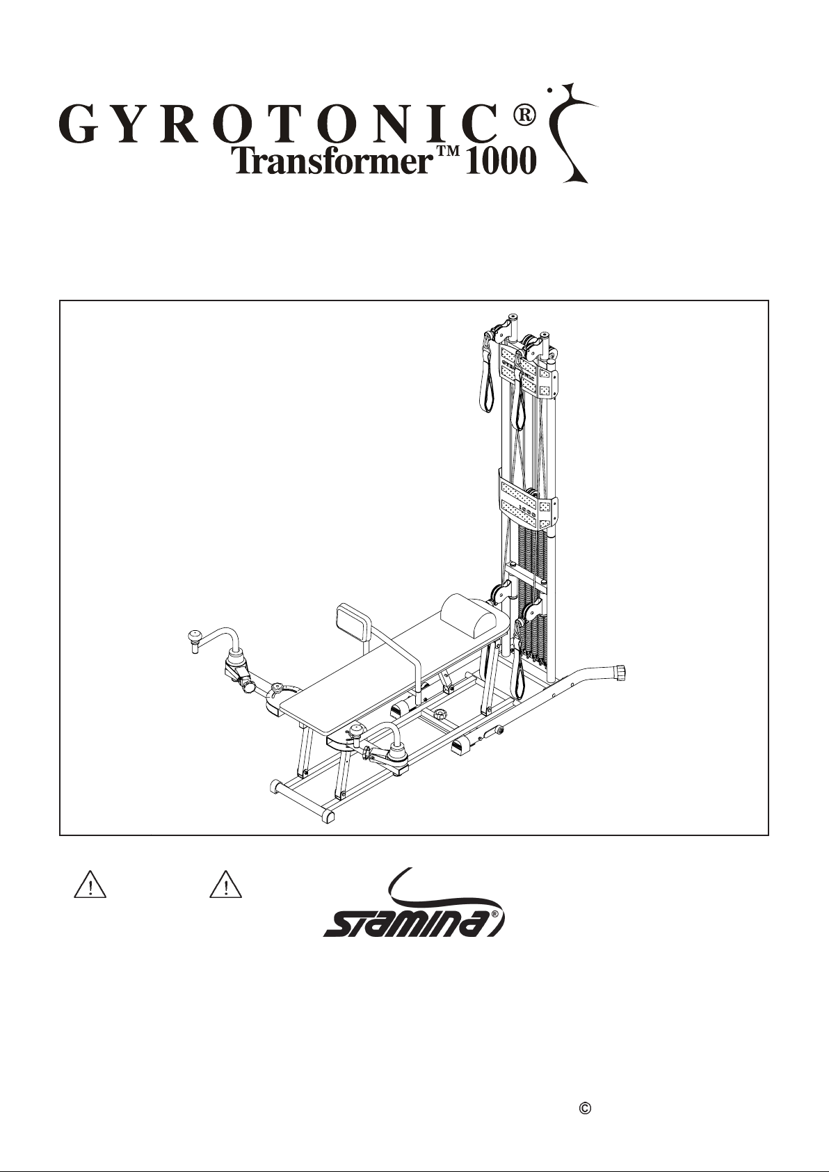
Owner's Manual
W A RNING
Exercise can present a health
risk. Consult a physician before
beginning any exercise program
with this equipment. If you feel
faint or dizzy, immediately
discontinue use of this
equipment.
W e ight on this product should not
exceed 300lbs./ 136kg/ 21st.
Model 55-6100U
Ma nuractured Exclusively
by Stamina Products
Licensed Under U.S. Patent
4,850,586
Other Patents Applied and
Are Pending
Product May Vary Slightly
From Pictured.
1-LA-GYRO-UK/1.0
2004 Stamina Products, Inc.
2004, 02
Page 2

2
Page 3

TABLE OF CONTENTS
Page Page
Safety Instructions ...................................
Before You Begin .....................................
Hardware Illustrations ..............................
Assembly Instruction ...............................
Operational Instructions ..........................
Storage ...................................................
Moving Your Trans former
TM
1000 .............
3
4
5
6
10
11
12
Maintenance..............................................
Conditioning Guidelines ...........................
Warm-up and Cool-Down ........................
Product Parts Drawing .............................
Parts List ..................................................
Notes .......................................................
Fax/Mail Ordering Form ...........................
SAFETY INSTRUCTIONS
WARNING:
1.
Read all warnings posted on the TRANSFORMER
Read this Owner's Manual and follow it carefully before using the TRANSFORMER
2.
sure that it is properly assembled and tightened bef ore use.
Do not allow children to play on the TRANSFORMER
3.
the TRANSFORMER
product with adult supervision.
Set up and operate the TRANSFORMER
4.
TRANSFORMER
Inspect the TRANSFORMER
5.
Tighten/replace any loose or worn components prior to using the TRANSFORMER
6.
When folding or unfolding the TRANSFORMER
7.
TRANSFORMER
Always make sure that the LOCKING PIN(37), EYEBOLT(39), and SNAP PIN(95) are properly in stalled.
8.
Before folding the bench down, ma ke sure that all three WHEELS(8) are up in the non-rolling position.
9.
Consult a physician prior to commencing an exercise program. If, at any time during exercise, you
10.
feel faint, dizzy, or experience pain, stop and consult your physician.
Follow your physicia n's recommendations in developing your own personal fitness program.
11.
Always choose the workout which best fits your physical strength and flexibility level. Know your
12.
limits and train within them. Always use common sense when exercising.
Do not wear loose or dangling clothing while using the TRANSFORMER
13.
Be careful to maintain your balance while using, mounting, dismounting, or assembling the
14.
TRANSFORMER
The TRANSFORMER
15.
The TRANSFORMER
16.
The TRANSFORMER
17.
facilities.
Any adjustment device shall not be left projecting.
18.
To reduce the risk of serious injury, read the following Safety Instructions before
using the TRANSFORMER
TM
1000 when it is in use by others. Children should only be allowed to use the
TM
1000 on loose rugs or uneven surfaces.
TM
1000 and make sure your hands are clear of any folding or pinch point.
TM
1000, loss of balance may result in a fall and serious bodily injury.
TM
TM
TM
TM
1000 should not be used by persons weighing over 300lbs./ 136kg/ 21st.
1000 should be used by only one person at a time.
1000 is for consumer use only. It is not for use in public or semipublic
TM
1000.
TM
1000.
TM
1000. Keep children and pets away from
TM
1000 on a solid level surface. Do not position the
1000 for worn or loose components prior to use.
TM
1000, keep all children away from the
TM
1000.
TM
TM
12
13
14
15
16
18
19
1000. Make
1000.
WARNING:
Before starting a ny exercise or conditioning progra m you should consult with your person al
physicia n to see if you require a complete physical exam. This is especi ally important if you
are over the age of 35, have never exercised before, are pregnant, or suffer from any
illness. READ AND FOLLOW THE SAFETY PRECAUTIONS. FAILURE TO FOLLOW
THESE INSTRUCTIONS CAN RESUL T IN SERIOUS BODILY INJURY.
3
Page 4
BEFORE YOU BEGIN
Thank you for choosing the
TRANSFORMER
1000. We take great pride in producing this quality
product and hope it will provide ma ny hours of quality
exercise to make you feel better , look better and en joy
life to its fullest.
Y es, it's a proven fa ct that a regular exercise program
can improve your physical and mental health. Too
often, our busy lifestyles limit our ti me and opportunity
to exercise. The
TRANSFORMER
a convenient and si mple method to begin your assault
on getting your body in sha pe and a chieving a happier
and healthier life style.
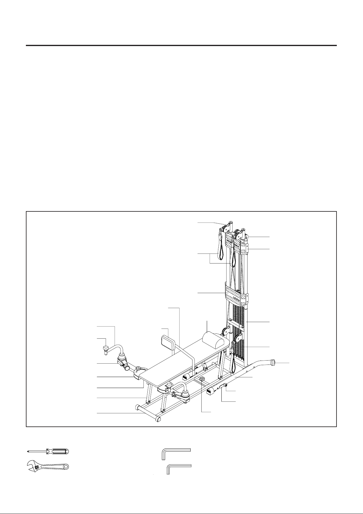
Before reading further, please review the drawing
below and familiarize yourself with the parts that are
labeled.
For your benefit, read this manual carefully before
using the
TRANSFORMER
TM
TM
1000 provides
1000.
TM
Pulley Frame
Although Stamina tries to manufacture its products
with the finest materials and uses the highest
standards of ma nufacturing, occasionally a part that
does not fit, is the incorrect size, or is otherwise
inappropriate is found. Even with the highest
inspection a nd quality controls in place these things
will happen occasionally. Please do not return the
product. For your convenience, Stamina has a
Customer Service Department with a toll-free
number. If a part is missing, does not fit, is the
incorrect size, or is otherwise inappropriate, please
call +44 (0)1242 702345 between 9.00am and 5.00
pm Monday to Friday. Our operators will be able to
assist you with your problem and the parts will be
mailed directly to your house.
Rotating Arm
Handle Knob
Right Support Arm
Right Arm Frame
Cushion
Bench Leg
Bench Base
Hand Straps
Lower Upright Guard
Back Cushion
Support
Back
Cushion
Pulley
Upper Upright
Guard
Pillow
Lower Upright
Springs
Leveling Cap
Left Ba se
Wheel
Pivot Plate
Securing Knob
THE FOLLOWING TOOLS ARE REQUIRED FOR ASSEMBLY :
Phillips Screwdriver
Adjustable Wrench
Allen Wrench (6mm) (Included)
Allen Wrench (5mm) (2 Required) (Included)
4
Page 5
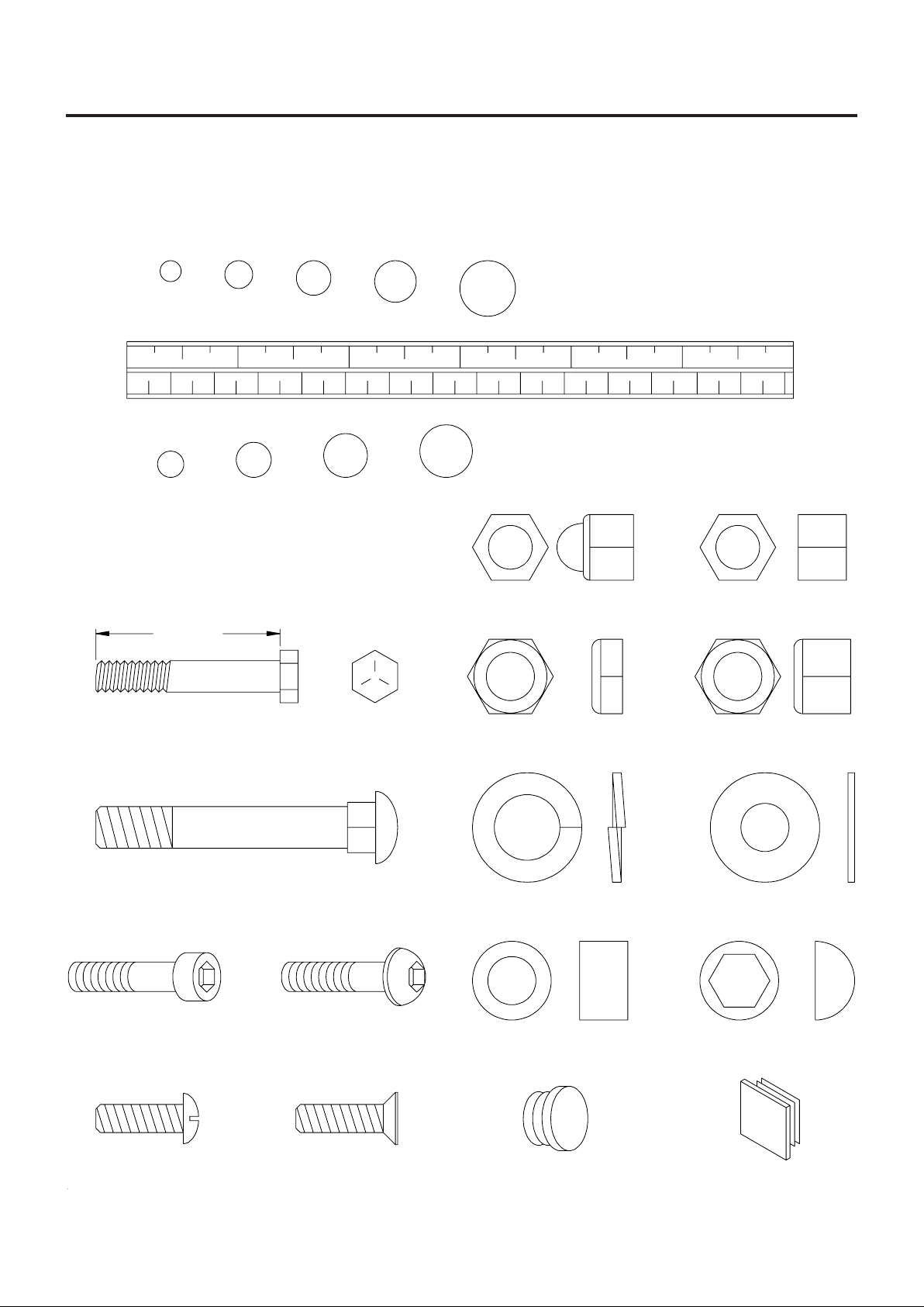
HARDWARE ILLUSTRATIONS
This chart is provided to help identify some of the small parts used in the assembly of this product. This
sheet may not include all the hardware needed to assemble your product. It is intended to be used as a
guide to help simplify your assembly process.
3/16" 1/4" 5/16" 3/8" 1/2"
INCHES
0 1/2 1/2 1/2 1/21/2 1/2123456
in.
mm.
0 10 20 30 40 50 60 70 80 90 100 110 120 130 140 150
MILLIMETERS
108126
Place washers, the end of bolts or screws on the
circles to check for the correct size. Use the small
scale to check the sizes of bolts a nd screws.
Length
Hex Head Bolt
Carriage Bolt
Socket Head Screw Button Hea d Screw
Standard NutAcorn Nut
Thin Nylock Nut Nylock Nut
Flat WasherLock Washer
Nut CapSpacer
Round Head Screw
Flat Head Screw
Round Plug Square Plug
5
Page 6
ASSEMBLY INSTRUCTIONS
Place all parts from the box in a cleared area and position them on the floor in front of you. Remove all
packing materi als from your area a nd pla ce the m ba ck into the box. Do not dispose of the pa cking materi als
until assembly is completed. Make sure you have all of the parts required for the machine. (Refer to the
assembly drawing). Read each step carefully before beginning. If you are missing a part please call our
customer care line for assistance on +44 (0)1242 702345.
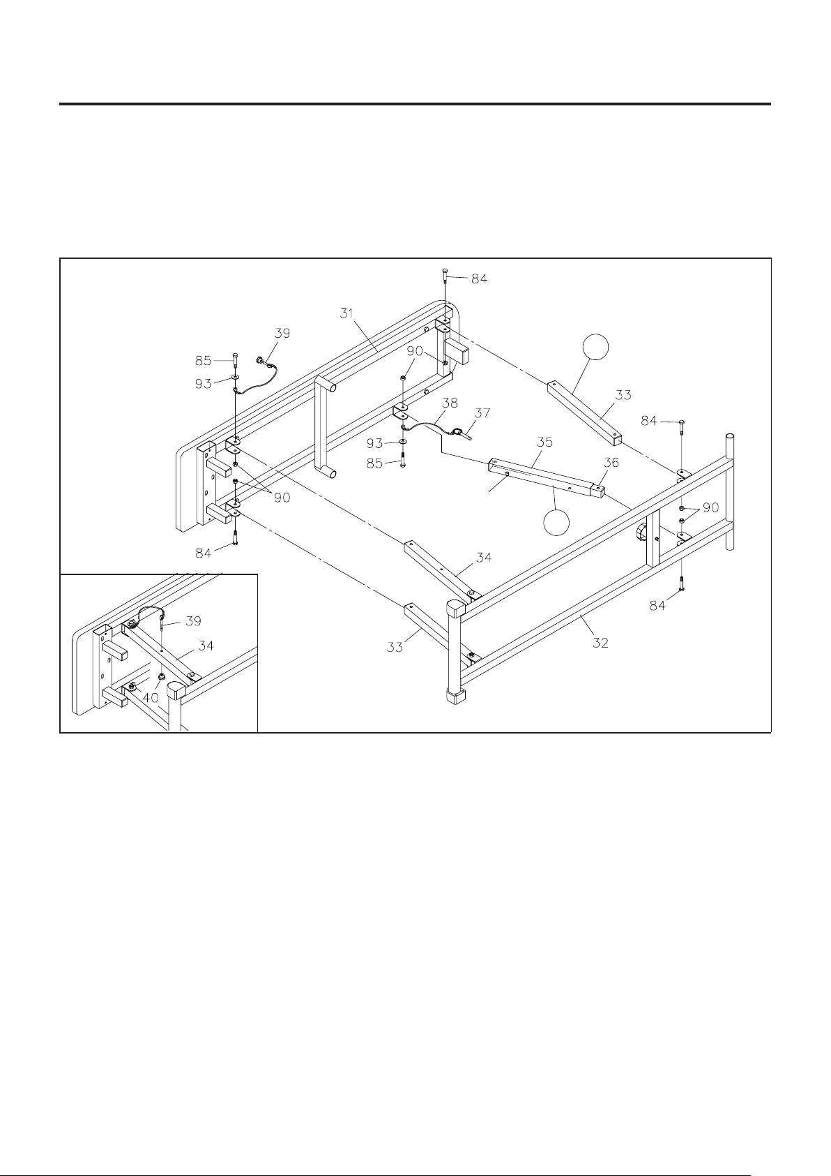
STEP 1, 2 & 3
L
BACK
Make the SNAP PIN(95)
face down.
R
STEP 2
FRONT
NOTE:
STEP 1: Set the BENCH BASE(32) on the floor as shown in the illustration above. Attach the two
BENCH LEGS(33) to the BENCH FRAME(31) and the BENCH BASE(32) with HEX BOL TS(M8 x 45mm)(84)
and NYLOCK NUTS(M8)(90).
STEP 2: Attach the BENCH LEG/w HOLE(34) and EYEBOLT(39) to the BENCH FRAME(31) with
HEX BOL T(M8 x 50mm)(85), W ASHER(M8)(93), and NYLOCK NUT(M8)(90). Store the EYEBOLT(39) by
Inserting the EYEBOLT(39) into the hole on the BENCH LEG/w HOLE(34) and secure with the SMALL
KNOB(40). Refer to the inset drawing.
There is a "L" decal on the BENCH LEG(33), and a "R" decal on the SUPPORT TUBE(35) and
INNER SUPPORT TUBE(36) assembly to help you identify their positions on the frame.
STEP 3: Ma ke the SNAP PIN(95) on the SUPPORT TUBE(35) fa ce down. Then atta ch the SUPPORT
TUBE(35) and LOCKING PIN(37) to the BENCH FRAME(31) with HEX BOLT(M8 x 50mm)(85),
WASHER(M8)(93), and NYLOCK NUT(M8)(90). Attach the INNER SUPPORT TUBE(36) to the BENCH
BASE(32) with HEX BOLT(M8 x 45mm)(84) and NYLOCK NUT(M8)(90).
NOTE:
If the SUPPORT TUBE(35) and the INNER SUPPORT TUBE(36) are locked together by the SNAP
PIN(95) during a sse mbly, press the SNAP PIN(95) down to release the tubes.
6
Page 7

ASSEMBLY INSTRUCTIONS
STEP 6
R
STEP 4, 5 & 7
L
NOTE:
STEP 4: Place the BENCH upright in the f olded position as shown above. Atta ch the RIGHT BASE(4)
onto the LOWER UPRIGHT(1) with CARRIAGE BOLTS(M8 x 65mm)(78) and NYLOCK NUTS(M8)(90).
Do not tighten until STEP 6.
STEP 5: Insert the round tube on the BENCH BASE(32) into the holes on the RIGHT and LEFT
BASES(4, 5), then attach the LEFT BASE(5) onto the LOWER UPRIGHT(1) with CARRIAGE BOLTS
(M8 x 65mm)(78) and NYLOCK NUTS(M8)(90). Do not tighten until STEP 6.
STEP 6: Slide the CROSS BAR(6) under the RIGHT and LEFT BASES(4, 5) and attach the CROSS
BAR(6) to the BENCH BASE(32) with the SECURING KNOB(41). Lay the FRAME ASSEMBLY on the
floor as shown in the illustration above. Attach the CROSS BAR(6) to the RIGHT and LEFT BASES(4, 5)
with BUTT ON HEAD BOL TS(M8 x 16mm)(88). Sta nd the FRAME ASSEMBL Y upright. Tighten NYLOCK
NUTS(90) in STEPS 4 and 5. Adjust the ENDCAPS(13) and LEVELING CAPS(14) so that the FRAME
ASSEMBLY sets flat on the floor.
There is a "L" decal on the LEFT BASE(5), and a "R" decal on the RIGHT BASE(4) to help you
identify their positions on the frame.
STEP 7: Atta ch the WHEEL SUPPORT(10) onto the LOWER UPRIGHT(1) with HEX BOL T(M8 x 40mm)
(83) and NYLOCK NUT(M8)(90).
7
Page 8

ASSEMBLY INSTRUCTIONS
BRACKET
STEP 8, 9, 10 & 11
STEP 8
Slide the UPPER UPRIGHT(2) onto the LOWER UPRIGHT(1) and secure with BUTTON HEAD BOLTS
(M8 x 16mm)(88).
STEP 9
To install the two ROPES(22) into the PULLEY FRAMES(15) on the LOWER UPRIGHT(1), remove the
PULLEY(16) from the PULLEY FRAME(15), pla ce the ROPE(24) into the PULLEY FRAME(15) and atta ch
the PULLEY(16) ba ck to the PULLEY FRAME(15) with ROUND HEAD BOL T(M6 x 14mm)(76) and BARREL
NUT(74). Repeat on the other side.
STEP 10
Attach the upper ends of the SPRINGS(27) to the bracket on the UPPER UPRIGHT(2). Hook the lower
ends of the SPRINGS(27) to the SPRING HOOKS(26) on the LOWER UPRIGHT(1).
STEP 11
Attach the UPPER UPRIGHT GUARD(100), the one with "GYROTONIC" printing, a nd the LOWER UPRIGHT
GUARD(101), the one with "1000" printing, onto the the UPPER UPRIGHT(2) with ROUND HEAD
BOLTS(M5 x 12mm)(79).
8
Page 9

ASSEMBLY INSTRUCTIONS
STEP 12, 13, 14 & 15
Remove
The M8 Nut
R
L
Remove
The M8 Nut
STEP 12: Unfold the Bench as follows:
Attach the BENCH BASE(32) to the Frame Assembly with the SECURING KNOB(41).
1.
Raise the Bench to the unfolded position. It may be necessary to hold the BENCH BASE(32) down with
2.
your toe.
Lock the Bench in its unfolded position by inserting the LOCKING PIN(37) into the hole in the SUPPORT
3.
TUBE(35).
STEP 13: There is a "R" decal on the RIGHT ARM FRAME(45), and a "L" decal on the LEFT ARM
FRAME(46). Attach the ROTATING ARM ASSEMBLIES onto the BENCH FRAME(31) by inserting the
ARM FRAMES(45, 46) into both sides of the BENCH FRAME(31) and securing with HEX BOLTS
(M8 x 16mm)(82) and WASHERS(M8)(93).
STEP 14: Remove the M8 nuts from the CARRIAGE BOLTS(M8 x 60)(77) on the ARM FRAMES
(45, 46) a nd install the LOCKING K NOBS(66) as shown. The M8 nuts are for shipping purposes only , they
may be discarded. Install ADJUSTMENT KNOBS(53) in ADJUSTMENT BLOCKS(52) as shown.
STEP 15: The PILLOW(73) and BACK CUSHION(72) are the optional accessories that can be used
with the BENCH for various exercises. Attach the BACK CUSHION(72) onto the BENCH FRAME(31) by
inserting the BACK CUSHION SUPPORT(71) into both sides of the BENCH FRAME(31).
STEP 16: The product will need a minimum floor space of 3.0m x 2.0m to use the product safely.
9
Page 10

OPERATIONAL INSTRUCTIONS
NOTE: The product will need a minimum floor space of 3.0m x 2.0m to use the product safely.
ARM ADJUSTMENT
The angle of the SUPPORT ARMS(47, 48) can be
adjusted for various exercises. Loosen the LOCKING
KNOBS(66) and adjust the angle of the SUPPORT
ARMS(47, 48). Refer to the marks on the ARM
FRAMES(45, 46) to make sure that both SUPPORT
ARMS(47, 48) are in the same position. Tighten the
LOCKING KNOBS(66) to secure the SUPPORT
ARMS(47, 48) in position.
RESISTANCE ADJUSTMENT A.
Use ADJUSTMENT K NOB(53) to change the resista nce of the Rotating
A.
Arms. Refer to illustration A.
Change the resistance of HAND STRAPS(21) by hooking different
B.
numbers of the SPRINGS(27) onto the PULLEY BRACKETS(25). Refer
to the following illustrations.
One Spring
Low Resista n c e
4 to 8 Pounds
Two Springs
Medium Resistance
8 to 14 Pounds
Three Springs
Maximum Re sistance
12 to 20 Pounds
We strongly recommend that you hang the springs
as shown in the illustrations above. This will allow the PULLEY BRACKETS
(25) to remain straight for smooth travel. All springs have equal resistance.
10
Page 11

STORAGE
1. 2.
TM
STORING THE TRANSFORMER
The TRANSFORMER
TM
1000 ca n be f olded a s illustrated for e a sy
1000
storage. Please follow the following process:
Adjust the SUPPORT ARMS(47, 48) and ROTATING
1.
ARMS(102) to the position shown in illustration 1. Remove
the EYEBOLT(39) from the BENCH LEG/w HOLE(34).
Remove the LOCKING PIN(37) from the SUPPORT TUBE(35)
2.
on the Bench. Press down the SNAP PIN(95) on the
SUPPORT TUBE(35) and fold the bench down. Lock it in
position by inserting the LOCKING PIN(37) into the hole in the
SUPPORT TUBE(35). Turn the PULLEY FRAMES (15) to
face to the in side of the UPRIGHT FRAME(1).
Loosen the SECURING KNOB(41). Fold the Bench up to the
3.
Upright Frame and lock it in position with the EYEBOLT (39)
and SMALL KNOB(40) as shown in illustration 3. The
EYEBOLT(39) must be attached to the Upright Frame as
shown. Hook the two HAND STRAPS(21) onto the tubes on
the BENCH FRAME(31) for more security.
3.
WARNING:
When folding or unfolding the TRANSFORMER
1.
1000 and ma ke sure your hands are clear of any folding or pinch point.
Always make sure that the LOCKING PIN(37) a nd EYEBOLT(39) are properly installed.
2.
Before folding the bench down, make sure that all three wheels are up in the non-rolling position.
3.
TM
1000, keep all children away from the TRANSFORMER
11
TM
Page 12

MOVING THE TRANSFORMER
TM
1000
There are three WHEELS(8) on the base for moving the TRANSFORMER
Please follow the following process to setup the wheels:
TM
1000 in its folded position.
NOTE:
You will have to tip the TRANSFORMER
TM
1000
slightly to the side to change the position of the wheels.
STEP 1
Insert the WHEEL SUPPORT(10) into the tube at the bottom
of the LOWER UPRIGHT(1).
STEP 2
Swing down the PIVOT PLA TES(7) and WHEELS(8) on both
sides of the base. You can now move the product on the
wheels.
STEP 1
STEP 2
MAINTENANCE
The safety and integrity designed into the TRANSFORMER
TM
TRANSFORMER
1000 is regularly examined f or damage and wear. Special attention should be given to
the following:
Inspect the Cord Assemblies for wear and looseness. Replace worn cords.
1.
Inspect the Velcro Strap Handles for damage. Replace damaged parts.
2.
Adjust the ADJUSTMENT KNOBS(53) and verify that the Brake System provides tension. The Brake
3.
System should provide many years of use.
Pull the HAND STRAPS(21) to verify that the SPRINGS(27) provides tension a nd the Cord/Pulley System
4.
travel smooth.
It is the sole responsibility of the user/owner to ensure that regular maintenance is performed.
5.
Worn or damaged components shall be replaced immedi ately or the TRANSFORMER
6.
from service until repair is made.
Only Stamina Products supplied components shall be used to maintain/repair the TRANSFORMER
7.
1000.
TM
Keep your TRANSFORMER
8.
1000 clean by wiping with an absorbent cloth after use.
TM
1000 can only be maintained when the
TM
1000 removed
TM
12
Page 13

CONDITIONING GUIDELINES
How you begin your exercise progra m depends on your physical condition. If you have been inactive for
several years, or are severely overweight, you must start slowly and increase your time on the
TRANSFORMER
Initially, you may be able to exercise only for a few minutes in your target zone, however, your aerobic
fitness will improve over the next six to e ight weeks. Don't be discouraged if it ta kes longer . It's i mportant to
work at your own pace. Ultimately, you'll be able to exercise continuously for 30 minutes. The better your
aerobic fitness, the harder you will have to work to stay in your target zone. Please remember these
essentials:
Have your doctor review your training and diet programs to advise you of a workout routine you
should adopt.
Begin your training program slowly with realistic goals that have been set by you and your doctor.
Monitor your pulse frequently. Establish your target heart rate base on your age and condition.
TM
1000 gradually: a few minutes per workout.
Set up your TRANSFORMER
TM
1000 on a flat, even surface at least 3 feet from walls and furniture.
EXERCISE INTENSITY
To maximize the benefits of exercising, it is important to exercise with the proper intensity. The proper
intensity level can be found by using your heart rate as a guide. For effective aerobic exercise, your heart
rate should be maintained at a level between 70% and 85% of your maximum heart rate as you exercise.
This is known a s your target zone. You can find your target zone in the table below . Target zones are listed
for both unconditioned and conditioned persons according to age.
During the first few months of your exercise program, keep your
heart rate near the low end of your target zone as you exercise.
After a few months, your heart rate can be increased gradually
until it is near the middle of your target zone as you exercise.
To measure your heart rate, stop
exercising but continue moving your
legs or walking around and pla ce two
fingers on your wrist. Take a sixsecond heartbeat count and multiply
the results by 10 to find your heart
rate. For exa mple, if your six-second
heartbeat count is 14, your heart rate
is 140 beats per minute. (A six-second count is used because
your heart rate will drop ra pidly when you stop exercising.) Adjust
the intensity of your exercise until your heart rate is at the proper
level.
13
Page 14

WARM-UP and COOL-DOWN
Warm-up The purpose of warming up is to prepare your body f or exercise and to mini mize injuries. Warm
up for two to five minutes before strength-training or aerobic exercising. Perform activities that raise your
heart rate and warm the working muscle s. Activitie s may include brisk walking, jogging, jumping ja cks, jump
rope, and running in place
Stretching Stretching while your muscles are warm after a proper warm-up and again after your strength
or aerobic training session is very important. Muscles stretch more easily at these times because of their
elevated temperature, which greatly reduces the risk of in jury . Stretches should be held for 15 to 30 seconds.
Do not bounce.
Suggested Stretching Exercises
Lower Body Stretch
Place feet shoulder-width
apart and lean forward.
Keep this position for 30
seconds using the body as a
natural weight to stretch the
backs of the legs.
DO NOT BOUNCE!
When the pull on the back of
the legs lessen, try a lower
position gradually.
Bent Torso Pulls
While sitting on the floor,
have legs apart one leg
straight and one knee bent.
Pull the chest down to touch
the thigh on the leg that is
bent and twist at the waist.
Hold this position at least 10
seconds. Repeat 10 times
on each side.
Floor Stretch
While sitting on the floor,
open the legs as wide as
possible. Stretch the upper
body toward the knee on the
right leg by using your arms
to pull your chest to your
thighs. Hold this stretch 10
to 30 seconds.
DO NOT BOUNCE!
Do this stretch 10 times.
Repeat the stretch with the
left leg.
Bent Over Leg Stretch
Stand with feet shoulderwidth apart and lean forward
as illustrated. Using the
arms, gently pull the upper
body towards the right leg.
Let the head hang down.
DO NOT BOUNCE!
Hold the position a minimum
of 10 seconds. Repeat
pulling the upper body to the
left leg. Do this stretch
several times slowly.
Remember always to check with your physician before starting any exercise program.
Cool-Down The purpose of cooling down is to return the body to its normal, or near normal, resting state
at the end of ea ch exercise se ssion. A proper cool-down slowly lowers your heart rate and allows blood to
return to the heart. Y our cool-down should include the stretche s listed above a nd should be completed after
each strength-training session.
14
Page 15

BACK
PRODUCT PARTS DRAWING
FRONT
15
Page 16

PARTS LIST
DIAGRAM# PART NAME QTY
1 Lower Upright 1
2 Upper Upright 1
4 Right Base 1
5 Left Base 1
6 Cross Bar 1
7 Pivot Plate 2
8 Wheel 3
9 Spacer 2
10 Wheel Support 1
11 Wheel Bracket 1
12 Nut Cap (8mm) 1
13 Endcap (50mm) 2
14 Leveling Cap (50mm) 2
15 Pulley Frame 4
16 Pulley 12
17 Pulley Bushing 4
18 Bushing (26.5mm) 4
19 Bushing /w chamfer (26.5mm) 4
20 Securing Cap 6
21 Hand Strap 4
22 Hook 4
23 Rope Stopper 4
24 Rope 2
25 Pulley Bracket 2
26 Spring Hook 12
27 Spring 6
28 Round Plug (25mm) 8
29 Round Plug (38mm) 2
30 Cushion 1
31 Bench Frame 1
32 Bench Base 1
33 Bench Leg 2
34 Bench Leg /w hole 1
35 Support Tube 1
36 Inner Support T ube 1
37 Locking Pin 1
38 Pin Cable 1
39 Eyebolt /w Cable 1
40 Small Knob (M6 x 1) 1
41 Securing Knob 1
42 Endcap (38mm) 2
43 Square Plug (25mm) 4
44 Square Plug (30mm) 9
45 Right Arm Frame 1
46 Left Arm Frame 1
47 Right Support Arm 1
48 Left Support Arm 1
16
Page 17

PARTS LIST
DIAGRAM# PART NAME QTY
49 Bushing (26mm) 4
50 Brake Block 2
51 Spring 2
52 Adjustment Block 2
53 Adjustment Knob 2
54 Brake Drum 2
55 Brake Strap 2
59 Sleeve 2
63 C Ring (11mm) 2
64 Bushing Plug 2
65 Handle Knob 2
66 Locking Knob 2
67 Plastic Washer (M8) 6
68 Large Washer (M8) 2
70 Rectangular Plug (30mm x 60mm) 3
71 Back Cushion Support 1
72 Back Cushion 1
73 Pillow 1
74 Barrel Nut (M6 x 1 x 24mm) 8
75 Barrel Nut (M6 x 1 x 44mm) 4
76 Bolt, Round Head (M6 x 1 x 14mm) 12
77 Carriage Bolt (M8 x 1.25 x 60mm) 2
78 Carriage Bolt (M8 x 1.25 x 65mm) 4
79 Bolt, Round Head (M5 x 0.8 x 12mm) 8
80 Bolt, Round Head (M6 x 1 x 25mm) 6
81 Bolt, Round Head (M6 x 1 x 40mm) 2
82 Bolt, Hex Head (M8 x 1.25 x 16mm) 4
83 Bolt, Hex Head (M8 x 1.25 x 40mm) 6
84 Bolt, Hex Head (M8 x 1.25 x 45mm) 6
85 Bolt, Hex Head (M8 x 1.25 x 50mm) 2
86 Bolt, Hex Head (M8 x 1.25 x 65mm) 2
87 Bolt, Flat Head (M8 x 1.25 x 15mm) 2
88 Bolt, Button Head (M8 x 1.25 x 16mm) 10
89 Bolt, Button Head (M10 x 1.5 x 55mm) 2
90 Nylock Nut (M8 x 1.25) 21
91 Nylock Nut (M10 x 1.5) 2
93 Washer (M8 x O.D 23mm) 6
94 Washer (M12 x O.D 23mm) 4
95 Snap Pin 1
96 Allen Wrench (5mm) 2
97 Allen Wrench (6mm) 1
98 Manual 1
99 Video Tape 1
100 Upper Upright Guard /w "GYROTONIC" Logo 1
101 Lower Upright Guard /w "1000" Logo 1
102 Rotating Arm 2
103 Brake Drum Cap 2
104 Long Pulley Bushing 4
17
Page 18

NOTES
18
Page 19

FAX/MAIL ORDERING FORM
Plea se do not return the product. For your convenience, Stamina has a Customer Service Department with
a toll-free number. Should a part be missing or a defective part found, please call +44 (0)1242 702345
between 9.00a m and 5.00pm on Monday to Friday or fill out the fax sheet ordering form below and fax it to
+44 (0)1242 702301. Our Customer Service De partment will be able to a ssist you with your problem a nd the
part will be mailed directly to your house.
TELEPHONE
CUSTOMER SERVICE
Tel: +44 (0)1242
702345
FAX
CUSTOMER SERVICE
Fax: +44 (0)1242
702301
ONLINE
CUSTOMER SERVICE
online@riobeauty.com
or
www.riobeauty.com
MAIL
RIO PRODUCTS
The Dezac Group Ltd
P.O. Box 17, Cheltenham
Glos. GL53 7ET
Detach and Mail or Fax the Form Below
THE DEZAC GROUP LTD
P.O. BOX 17, CHELTENHAM
GLOUCESTERSHIRE GL53 7ET
Name:..............................................................................................................................................................
Address: ..........................................................................................................................................................
...................................................................................................... Post Code:...............................................
IMPORTANT: We must have your phone number in order to process the order!
Daytime number:................................................. Evening number: ..............................................................
Date Purchased:......................................................Model number: ..............................................................
Purchased From: .............................................................................................................................................
IMPORTANT: Before filling out the form below make sure you have the right information.
Refer to the parts list to make sure you're ordering the right parts!
PART # DESCRIPTION QUANTITY
EXAMPLE:
1 Rear Unit Assembly
 Loading...