

ST TSH60 User Manual
TSH60,61,62,63,64
Wide-Band, Low-Power Operational Amplifiers
with Standby
■ 5V, ±5V specifications
■ Gain-bandwidth product: 60MHz
■ Slew-rate: 80V/µs
■ Output current: up to 45mA
■ Input/output rail-to-rail
■ Specified for 150Ω load
■ Low distortion, THD: 0.1%
■ SO packages
Description
The TSH6x series offers single, dual, triple and
quad operational amplifiers featuring high video
performances.
The TSH6x op-amps can be used in consumer
video applications, such as set-top boxes, DVD
players and recorders, or TVs, as either video
buffers or video line drivers. Their performances
guarantee excellent video quality, enhancing the
performance of your video solution.
Running at single supply voltage from 5V to 12V,
amplifiers feature large output voltage swing and
high output current capability to drive standard
150Ω loads.
The TSH61 and TSH63 also feature standby
inputs, allowing the op amps to be put into a
standby mode with low power consumption and
high output impedance.
For easy integration into video applications, the
TSH6x series is proposed in standard SO8 and
SO14 packages.
Applications
■ Standard definition video buffers
■ Set-top boxes
■ DVD players and recorders
■ Analog and digital TVs
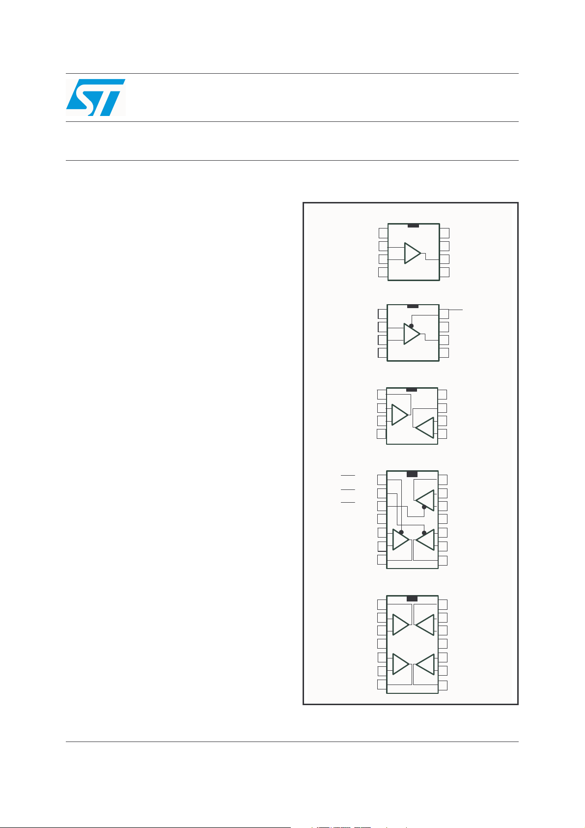
Pin connections (top view)
TSH60 : SO8
TSH60 : SO8
NC
NC
NC
NC
NC
1
1
1
_
_
_
2
2
Inverting Input
Inverting Input
Inverting Input
Non Inverting Input
Non Inverting Input
Non Inverting Input
Inverting Input
Inverting Input
Inverting Input
Non Inverting Input
Non Inverting Input
Non Inverting Input
Inverting Inpu t1 Outpu t2
Inverting Inpu t1 Outpu t2
Inverting Inpu t1 Outpu t2
Non Inverting Input1
Non Inverting Input1
Non Inverting Input1
STANDBY1
STANDBY1
STANDBY1
STANDBY2
STANDBY2
STANDBY2
STANDBY3
STANDBY3
STANDBY3
Non Inverting Input1
Non Inverting Input1
Non Inverting Input1
Inverting Input1
Inverting Input1
Inverting Input1
Inverting Input1
Inverting Input1
Inverting Input1
Non Inverting Input1
Non Inverting Input1
Non Inverting Input1
Non Inverting Input2
Non Inverting Input2
Non Inverting Input2
Inverting Input2
Inverting Input2
Inverting Input2
2
3
3
3
VCC -
VCC -
VCC -
4
4
4
TSH61 : SO8
TSH61 : SO8
NC
NC
NC
1
1
1
2
2
2
3
3
3
VCC -
VCC -
VCC -
4
4
4
TSH62 : SO8
TSH62 : SO8
Output1
Output1
Output1
1
1
1
2
2
2
3
3
3
VCC -
VCC -
VCC -
4
4
4
TSH63 : SO14
TSH63 : SO14
1
1
1
2
2
2
3
3
3
VCC +
VCC +
VCC +
5
5
5
6
6
6
7
7
7
Output1
Output1
Output1
TSH64 : SO14
TSH64 : SO14
1
1
1
Output1
Output1
Output1
2
2
2
3
3
3
VCC +
VCC +
VCC +
5
5
5
6
6
6
Output2
7
Output2
7
Output2
7
+
+
+
_
_
_
+
+
+
_
_
_
+
+
+
+
+
+
_
_
_
_
_
_
+
+
+
+
+
+
_
_
_
NC
8
8
8
7
7
7
VCC +
VCC +
VCC +
6
Output
6
Output
6
Output
NC
NC
NC
5
5
5
8
8
8
STANDB Y
STANDB Y
STANDB Y
7
7
7
VCC +
VCC +
VCC +
6
Output
6
Output
6
Output
NC
NC
NC
5
5
5
VCC +
VCC +
VCC +
8
8
8
7
7
7
Inverting Input2
Inverting Input2
Inverting Input2
_
_
_
6
6
6
+
+
+
Non Inverting Input2
Non Inverting Input2
Non Inverting Input2
5
5
5
14
14
14
Output3
Output3
Output3
13
13
13
Inverting Input3
Inverting Input3
Inverting Input3
_
_
_
+
+
+
Non Inverting Input3
Non Inverting Input3
Non Inverting Input3
12
12
12
VCC -
VCC -
VCC -
114
114
114
10
10
10
Non Inverting Input2
Non Inverting Input2
Non Inverting Input2
+
+
+
_
_
_
Inverting Input2
Inverting Input2
Inverting Input2
9
9
9
Output2
Output2
Output2
8
8
8
14
14
14
Output4
Output4
Output4
13
13
13
Inverting Input4
Inverting Input4
Inverting Input4
_
_
_
+
+
+
Non Inverting Input4
Non Inverting Input4
Non Inverting Input4
12
12
12
114
114
114
VCC -
VCC -
VCC -
10
10
10
Non Inverting Input3
Non Inverting Input3
Non Inverting Input3
+
+
+
_
_
_
Inverting Input3
Inverting Input3
Inverting Input3
9
9
9
Output3
Output3
Output3
8
8
8
March 2006 Rev. 1 1/13
www.st.com
13

Order Codes TSH60,61,62,63,64
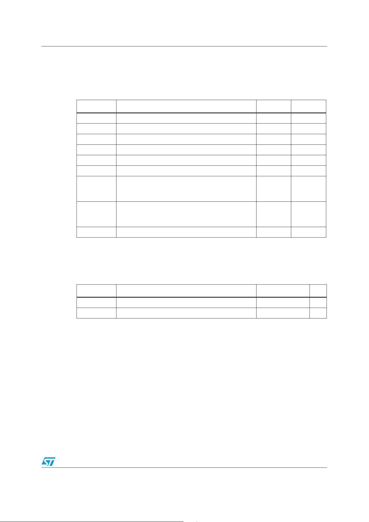
1 Order Codes
Type Temperature Range Packages Packing Marking
TSH60CD/CDT
TSH61CD/CDT TSH61C
TSH62CD/CDT TSH62C
TSH63CD/CDT
TSH64CD/CDT TSH64C
0°C to 70°C
SO8
Tube or Tape & Reel
SO14
TSH60C
TSH63C
2/13
TSH60,61,62,63,64 Absolute Maximum Ratings and Operating Conditions
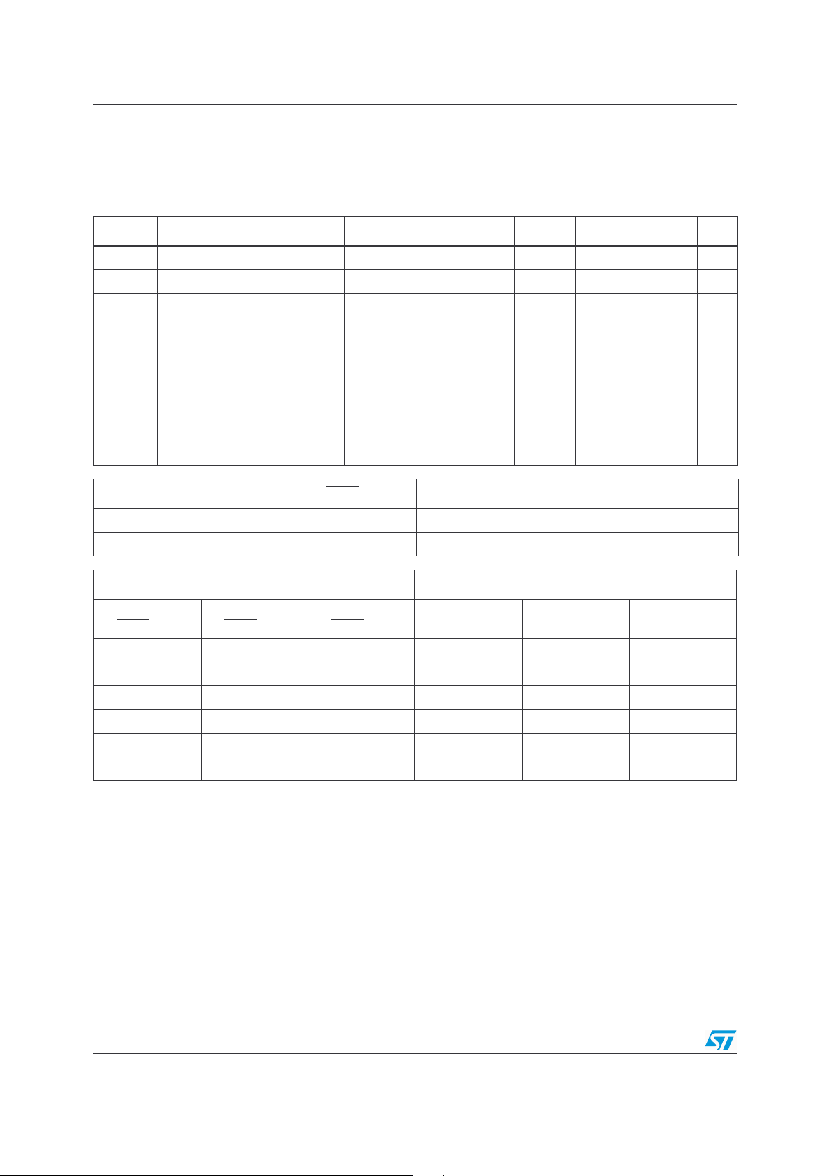
2 Absolute Maximum Ratings and Operating
Conditions
Table 1. Absolute maximum ratings
Symbol Parameter Value Unit
(3)
(1)
(2)
(4)
14 V
±2V
±6V
28
°C/W
22
157
°C/W
125
T
V
T
R
R
CC
V
V
oper
stg
T
thjc
thja
Supply Voltage
id
i
Differential Input Voltage
Input Voltage
Operating Free Air Temperature Range 0 to +70 °C
Storage Temperature -65 to +150 °C
j
Maximum Junction Temperature 150 °C
Thermal Resistance Junction to Case
SO8
SO14
Thermal Resistance Junction to Ambiant Area
SO8
SO14
ESD HumanBodyModel 2 kV
1. All voltages values, except differential voltage are with respect to network ground terminal
2. Differential voltages are non-inverting input terminal with respect to the inverting terminal
3. The magnitude of input and output must never exceed VCC +0.3V
4. Short-circuits can cause excessive heating
Table 2. Operating conditions
Symbol Parameter Value Unit
V
CC
V
IC
Supply Voltage 4.5 to 12 V
Common Mode Input Voltage Range V
CC
-
to (V
+
-1.1) V
CC
3/13
Standby Mode TSH60,61,62,63,64
3 Standby Mode
Table 3. V
+
(positive supply voltage), V
CC
-
(negative supply voltage, or ground), T
CC
amb
= 25°C
(unless otherwise specified)
Symbol Parameter Test Conditions Min. Typ. Max. Unit
Vl
ow
V
high
I
CC STBY
Z
out
T
on
T
off
Standby Low Level V
Standby High Level (V
Current Consumption per
Operator when STANDBY is
Active
Output Impedance (Rout//Cout)
pin 8 (TSH61) to V
pin 1,2 or 3 (TSH63) to V
R
out
C
out
CC
-
CC
CC
-
Time from Standby Mode to
Active Mode
Time from Active Mode to
Standby Mode
TSH61 Standby Control pin 8 (STBY
V
low
V
high
Down to I
CC STBY
= 10µA10 µs
) Operator Status
TSH63 Standby Control Operator Status
-
CC
-
+2) (V
20 55 µA
10
17
2 µs
Standby
Active
(V
CC
-
+0.8) V
+
)V
CC
MΩ
pF
pin 1
(STBY
OP1)
V
low
V
high
xV
xV
xxV
xxV
pin 2
(STBY OP2)
pin 3
(STBY OP3)
x x Standby x x
xxActivexx
low
high
x x Standby x
low
high
OP1 OP1 OP3
xActivex
x x Standby
xxActive
4/13
 Loading...