How it Works
Log In / Sign Up
Buy Points
How it Works
FAQ
Contact Us
Questions and Suggestions
Users
ST
Loading...
T
TDA7404
TDA7415CB
TDA7416
TDA7417
TDA7418
TDA7419
TDA7430
TDA7439DS
TDA7440
TDA7448
TDA7454
TDA7468
TDA7479
TDA7491HV
TDA7491LP
TDA7491MV
TDA7491P
TDA7492
TDA7492P
TDA7493
TDA7496
TDA7496SA
TDA7498
TDA7498E
TDA7498L
TDA7498MV
TDA7505
TDA7512F
TDA7528
TDA7529
TDA7540B
TDA7540N
TDA7541
TDA7541B
TDA7560
TDA7561
TDA7562
TDA7563A
TDA7563B
TDA7564B
TDA7565
TDA7566
TDA7567PD
TDA7570
TDA7572
TDA7575B
TDA7590
TDA7706
TDA7718N
TDA7719
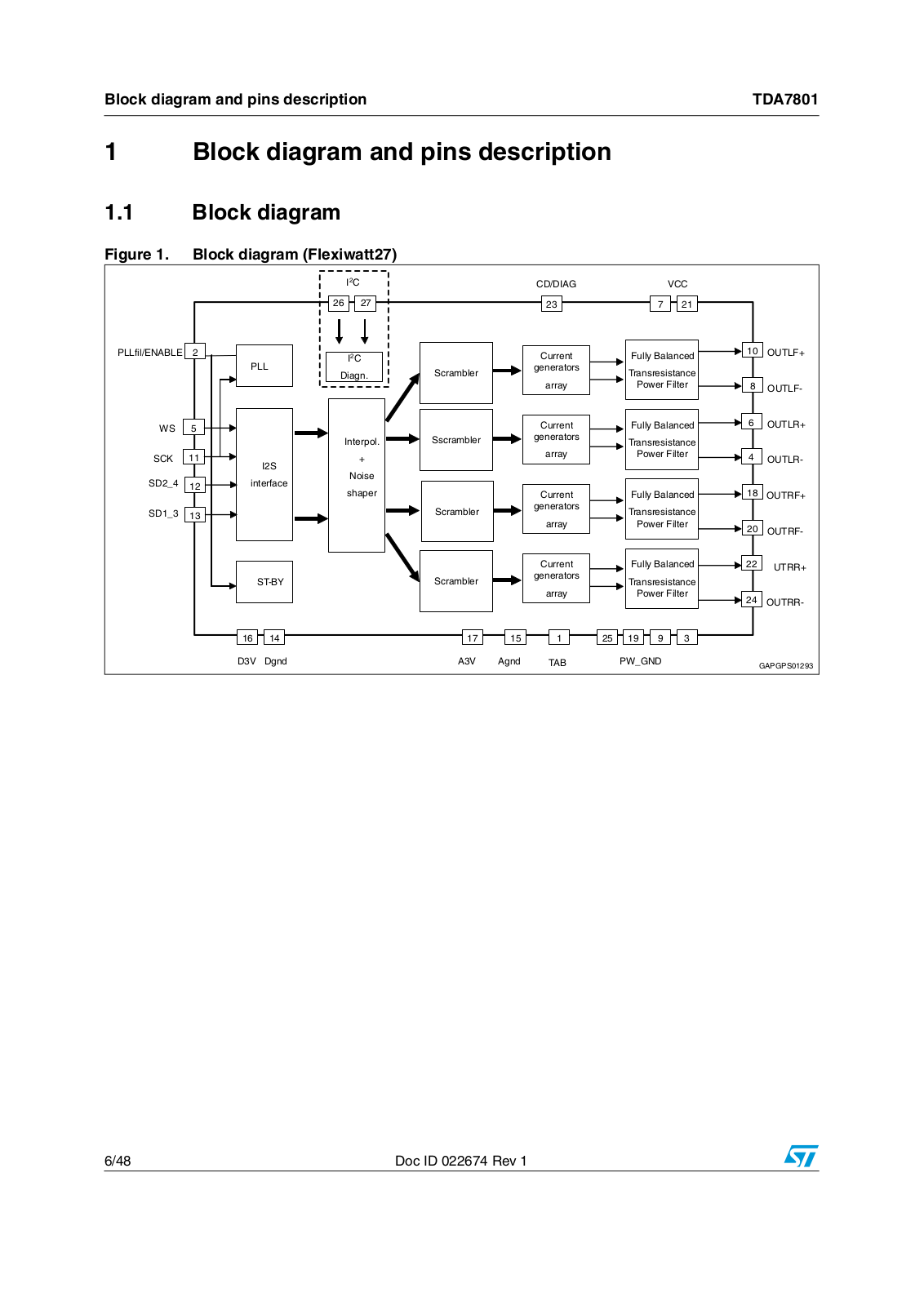
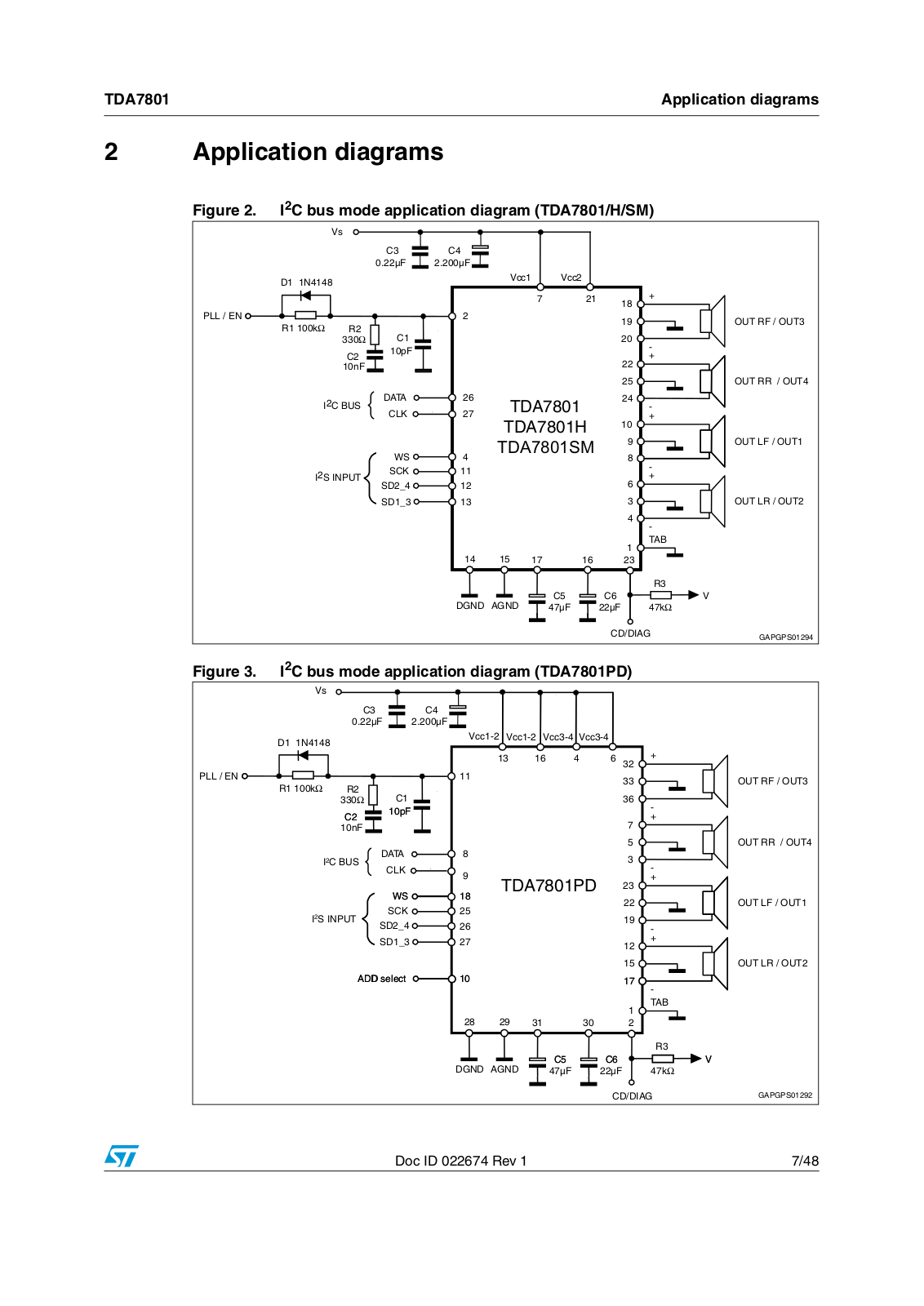
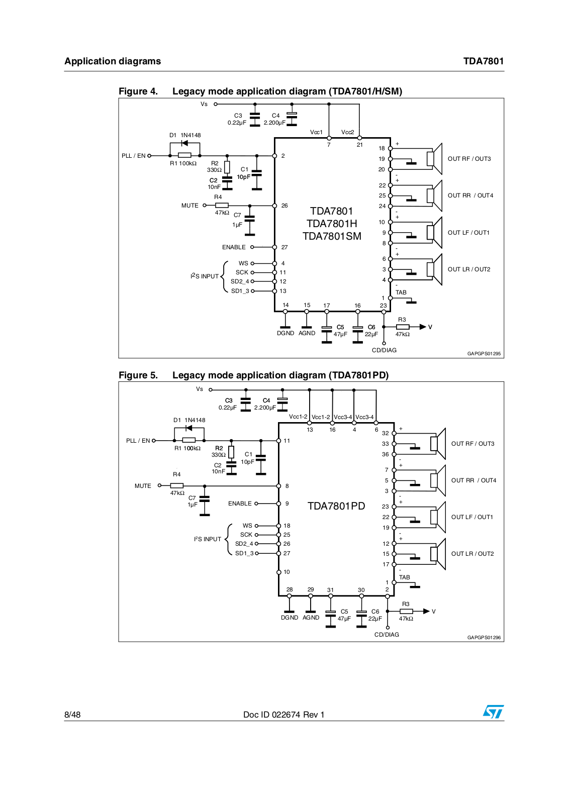
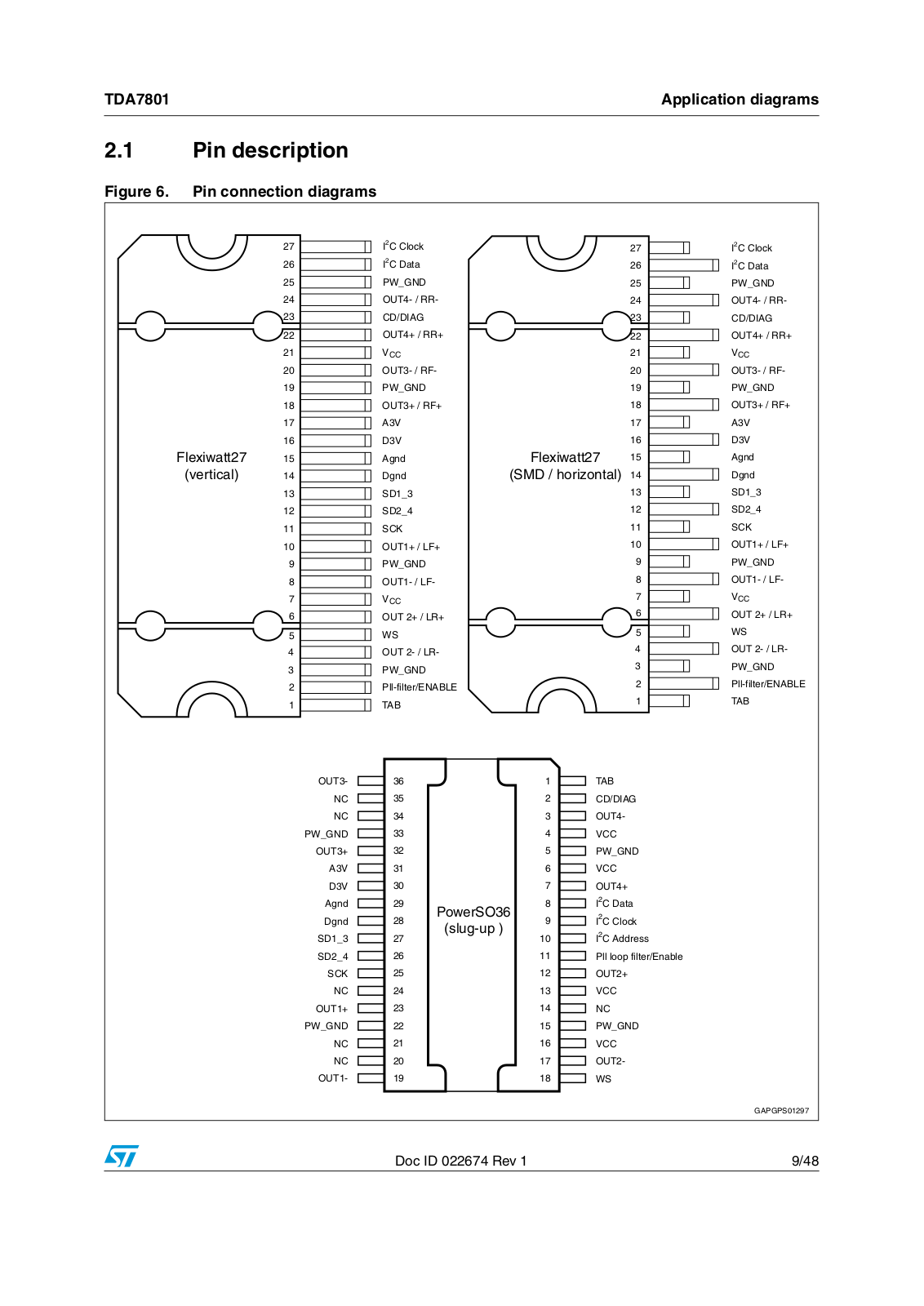
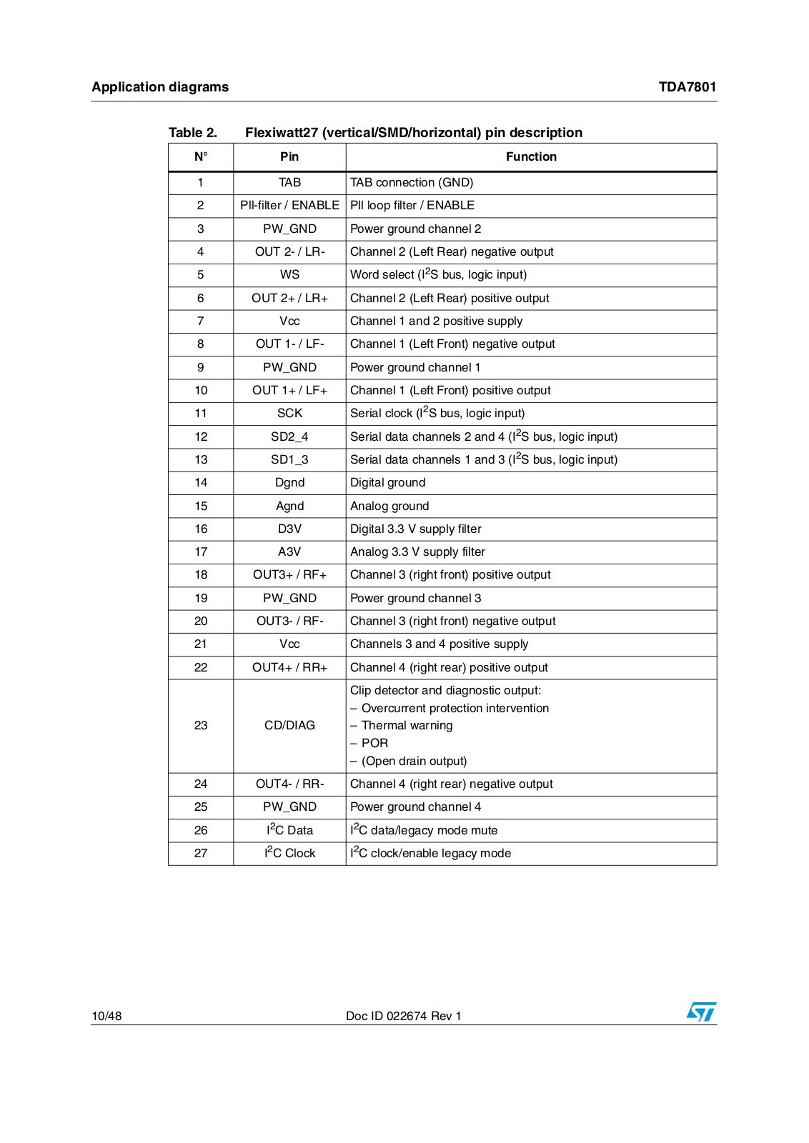
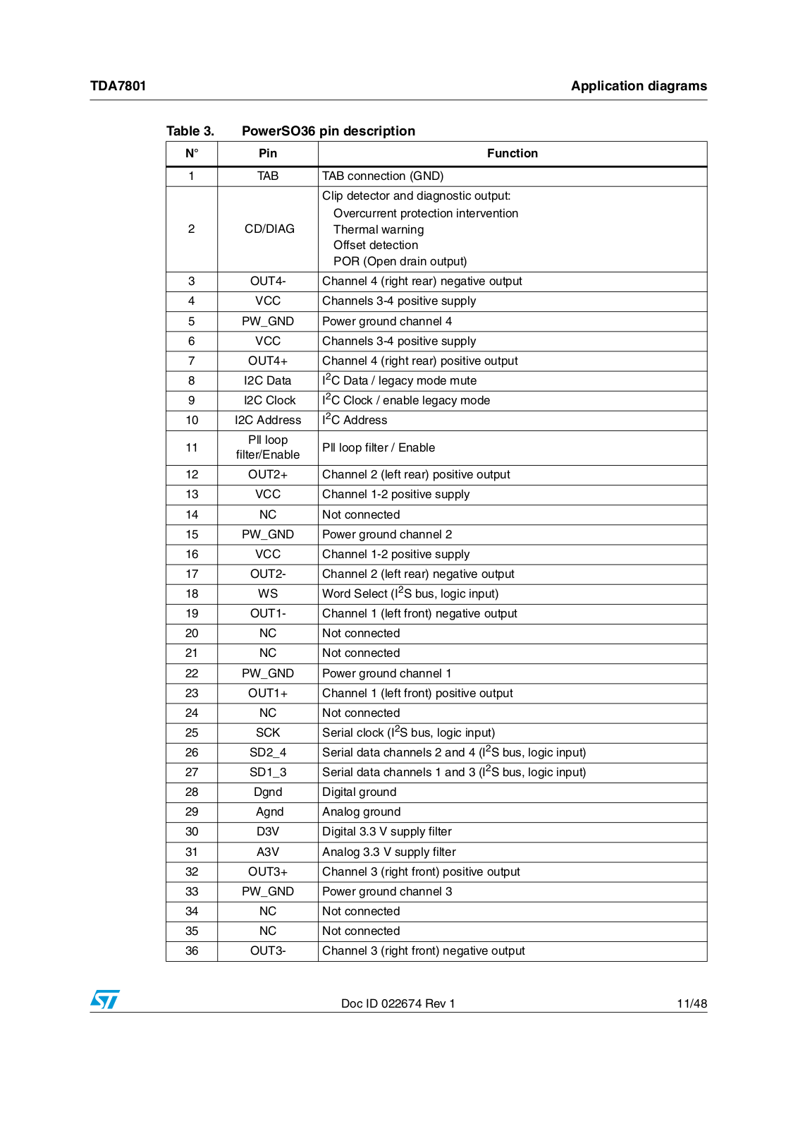
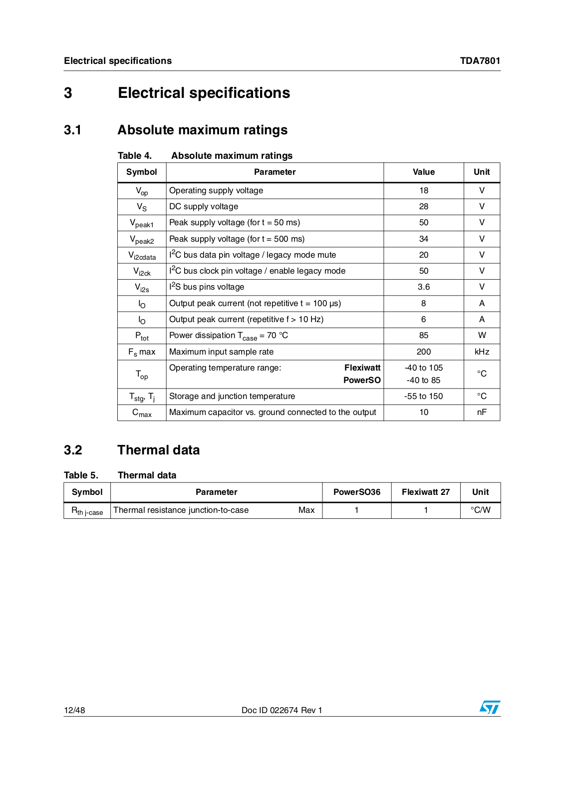
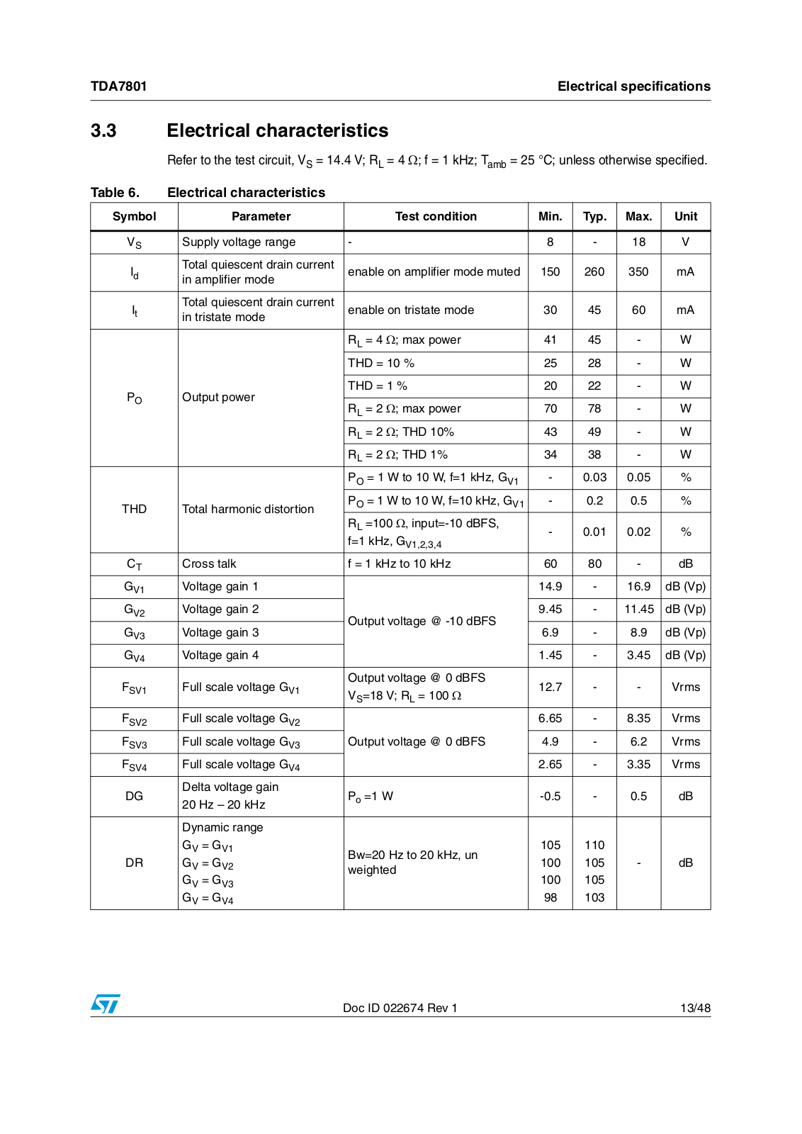
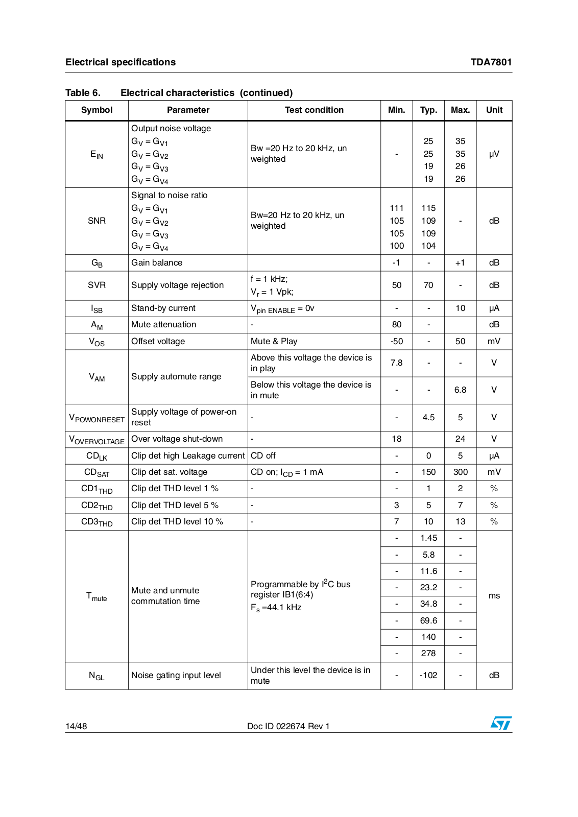
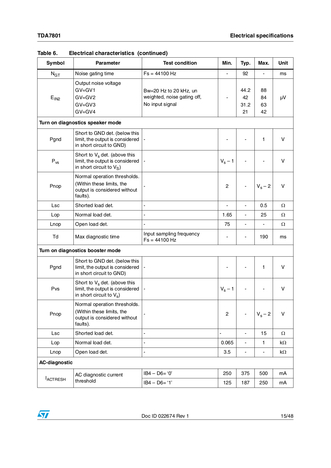
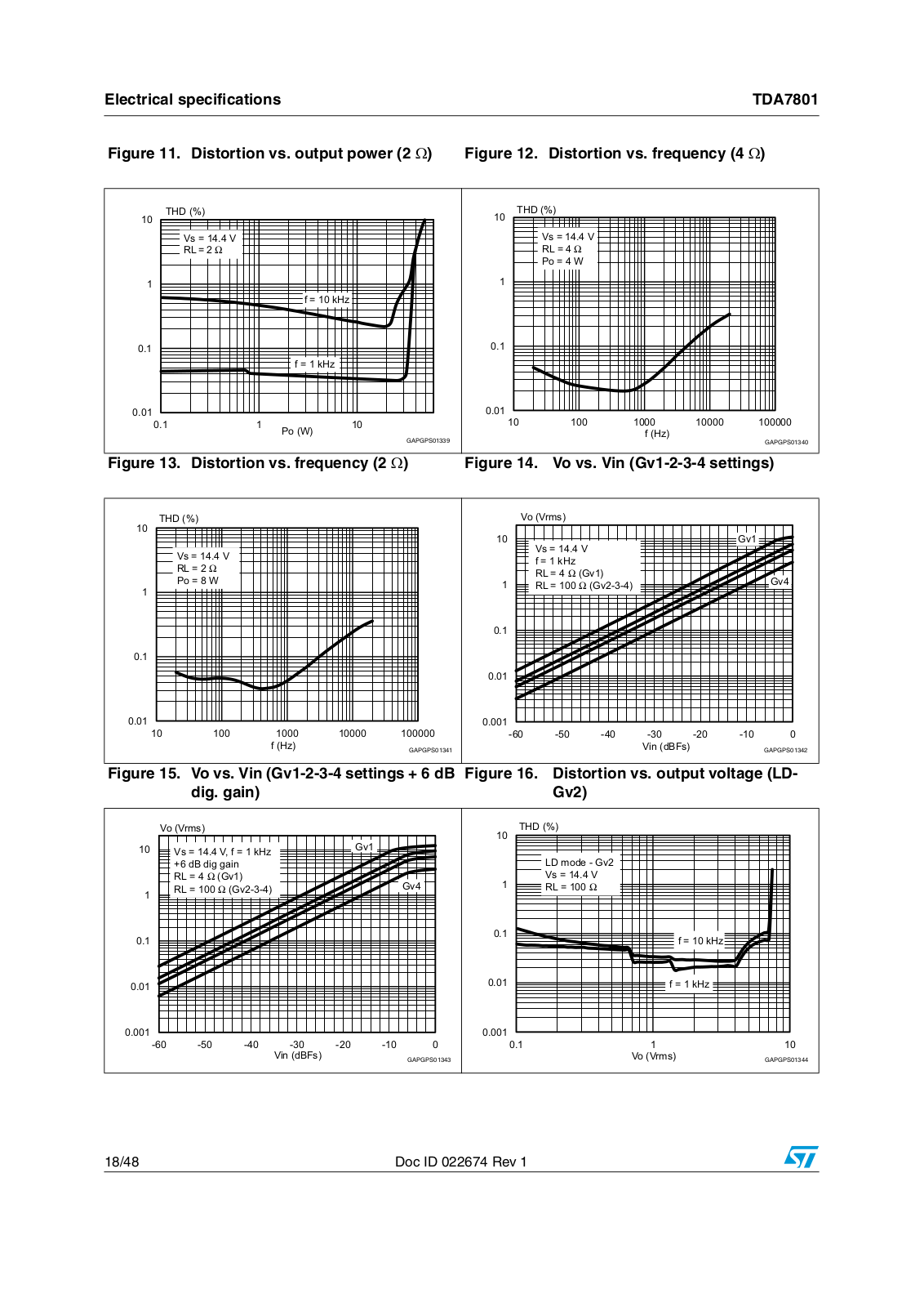
TDA7801
TDA7850
TDA7850A
TDA7851A
TDA7851F
TDA9112
TDA9113
TDA9115
TDA9116
TDA911 Series
TDE1708DFT
TDE1737
TDE1747
TDE1767
TDE1787
TDE1798
TDE1897C
TDE1897R
TDE1898C
TDE1898R
TDE3247
TDR001V1
TDR004V1
TDR005V1
TDR006V1
TDR007V1
TDR009V1
TDR010V1
TDR011V1
TDR013V1
2
TDR014V1
TDR015V1
TDR016V1
TDR017V1
2
TDR019V1
2
TDR020V1
TDR021V1
TDR022V1
TDR023V1
TDR025V1
TDR027V1
TDR028V1
TDR029V1
TEA1014
TEA2025
TEA3718
TEA6420
TEA6422
TEA6425
Teseo-LIV3F
2
Loading...
Loading...
Nothing found
TDA7801
User Manual
48 pgs
997.36 Kb
0
Table of contents
Loading...
ST TDA7801 User Manual
...
ST User Manual
Download
Specifications and Main Features
Frequently Asked Questions
User Manual
Download
Loading...
+
hidden pages
Unhide
You need points to download manuals.
1 point = 1 manual.
You can buy points or you can get point for every manual you upload.
Buy points
Upload your manuals
 Loading...