

FM/AM car-radio receiver front-end for IF-sampling systems
Features
■ High-performance AM/FM front-end chip for IF-
sampling car-radio tuners
■ Compatible with AM(LW, MW, SW) / FM(EU,
US, JAPAN, OIRT) / Weather Band / HD-Radio
/ DRM applications
■ Ready for multi-tuner applications (phase
diversity, background tuner)
■ Dual input FM-mixer with high image rejection,
specialized for different front-end circuits
■ Integrated AM preamplifier and tank for lower-
cost applications
■ Fully integrated tuning PLL with two VCO's for
diversity systems
■ World tuning capable
■ Integrated IF tank
■ AGC controlled IF amplifier with four inputs for
connection of up to four ceramic filters
■ Fully electronically adjustable
2
■ I
C/SPI controlled
Description
TDA7528
with fully integrated VCO
LQFP64
Its field of use includes all the current radio
broadcast services in the range of 50kHz to
163MHz for AM radio, FM radio and US weather
band. Digital standards such as DRM and HD
radio can also be handled. A single
supterheterodyne architecture with 10.7 MHz IFfrequency provides high dynamic range.
The IMR mixer has separate input and output
stages for AM frequency bands up to 30 MHz and
for FM frequencies above 30 MHz.
The integrated AM-preamplifier and the fully
integrated low-pass filter enable low cost
applications. Two FM inputs with different noise /
IP3 parameter, provide full flexibility for the prestage circuitry. Each mixer output is able to drive
two IF-filters, which can be selected by the
different IF-amplifier inputs.
The TDA7528 is a front-end module for use in car
radio receivers with digital IF processing, using
the STA3004, respectively the STA3005 backend
The fast tuning PLL controls two different VCO,
which are designed to operate without frequency
overlap.
IC.
Table 1. Device summary
Order code Package Packing
TDA7528 LQFP64 exposed pad (10x10x1.4 mm) Tray
December 2009 Doc ID 13141 Rev 6 1/65
www.st.com
1

Contents TDA7528
Contents
1 Product description . . . . . . . . . . . . . . . . . . . . . . . . . . . . . . . . . . . . . . . . . 8
1.1 Summary . . . . . . . . . . . . . . . . . . . . . . . . . . . . . . . . . . . . . . . . . . . . . . . . . . 8
1.2 Block diagram . . . . . . . . . . . . . . . . . . . . . . . . . . . . . . . . . . . . . . . . . . . . . . . 9
2 Pin description . . . . . . . . . . . . . . . . . . . . . . . . . . . . . . . . . . . . . . . . . . . . 10
2.1 Pin connection . . . . . . . . . . . . . . . . . . . . . . . . . . . . . . . . . . . . . . . . . . . . . 10
2.2 Pin description . . . . . . . . . . . . . . . . . . . . . . . . . . . . . . . . . . . . . . . . . . . . . 10
3 Electrical characteristics . . . . . . . . . . . . . . . . . . . . . . . . . . . . . . . . . . . . 13
3.1 Absolute maximum ratings . . . . . . . . . . . . . . . . . . . . . . . . . . . . . . . . . . . . 13
3.2 General parameters . . . . . . . . . . . . . . . . . . . . . . . . . . . . . . . . . . . . . . . . . 13
3.3 Power management and voltage regulator . . . . . . . . . . . . . . . . . . . . . . . . 14
3.3.1 Power management . . . . . . . . . . . . . . . . . . . . . . . . . . . . . . . . . . . . . . . . 14
3.3.2 Power-on circuit and low supply voltage detector . . . . . . . . . . . . . . . . . 14
3.3.3 Voltage regulator . . . . . . . . . . . . . . . . . . . . . . . . . . . . . . . . . . . . . . . . . . 15
3.4 FM - Section . . . . . . . . . . . . . . . . . . . . . . . . . . . . . . . . . . . . . . . . . . . . . . . 16
3.4.1 IMR and active balun . . . . . . . . . . . . . . . . . . . . . . . . . . . . . . . . . . . . . . . 16
3.4.2 FM AGC . . . . . . . . . . . . . . . . . . . . . . . . . . . . . . . . . . . . . . . . . . . . . . . . . 18
3.5 AM - Section . . . . . . . . . . . . . . . . . . . . . . . . . . . . . . . . . . . . . . . . . . . . . . . 21
3.5.1 AM LNA . . . . . . . . . . . . . . . . . . . . . . . . . . . . . . . . . . . . . . . . . . . . . . . . . 21
3.5.2 Switchable LPF 4
3.5.3 IMR and active balun . . . . . . . . . . . . . . . . . . . . . . . . . . . . . . . . . . . . . . . 22
3.5.4 AM AGC . . . . . . . . . . . . . . . . . . . . . . . . . . . . . . . . . . . . . . . . . . . . . . . . . 24
th
order . . . . . . . . . . . . . . . . . . . . . . . . . . . . . . . . . . . . 21
3.6 IF - Section . . . . . . . . . . . . . . . . . . . . . . . . . . . . . . . . . . . . . . . . . . . . . . . . 27
3.6.1 IF-Amplifier . . . . . . . . . . . . . . . . . . . . . . . . . . . . . . . . . . . . . . . . . . . . . . 27
3.6.2 IF-AGC . . . . . . . . . . . . . . . . . . . . . . . . . . . . . . . . . . . . . . . . . . . . . . . . . . 29
3.6.3 IF buffer amplifier . . . . . . . . . . . . . . . . . . . . . . . . . . . . . . . . . . . . . . . . . . 30
3.7 Phase Locked Loop . . . . . . . . . . . . . . . . . . . . . . . . . . . . . . . . . . . . . . . . . 30
3.7.1 VCO . . . . . . . . . . . . . . . . . . . . . . . . . . . . . . . . . . . . . . . . . . . . . . . . . . . . 31
3.7.2 Reference oscillator / reference frequency input buffer . . . . . . . . . . . . . 32
3.7.3 Divider . . . . . . . . . . . . . . . . . . . . . . . . . . . . . . . . . . . . . . . . . . . . . . . . . . 32
3.7.4 Phase frequency detector and charge pump . . . . . . . . . . . . . . . . . . . . . 33
3.8 Temperature sensor . . . . . . . . . . . . . . . . . . . . . . . . . . . . . . . . . . . . . . . . . 33
2/65 Doc ID 13141 Rev 6

TDA7528 Contents
3.9 D/A-converter . . . . . . . . . . . . . . . . . . . . . . . . . . . . . . . . . . . . . . . . . . . . . . 34
3.10 A/D-converter . . . . . . . . . . . . . . . . . . . . . . . . . . . . . . . . . . . . . . . . . . . . . . 35
3.11 GPIO - general purpose I/O interface pins . . . . . . . . . . . . . . . . . . . . . . . . 36
3.11.1 Serial data interface . . . . . . . . . . . . . . . . . . . . . . . . . . . . . . . . . . . . . . . . 36
3.11.2 Communication using the I
3.11.3 Communication using the SPI protocol . . . . . . . . . . . . . . . . . . . . . . . . . 38
2
C protocol . . . . . . . . . . . . . . . . . . . . . . . . . 37
4 Application information . . . . . . . . . . . . . . . . . . . . . . . . . . . . . . . . . . . . . 40
5 Programming information . . . . . . . . . . . . . . . . . . . . . . . . . . . . . . . . . . . 41
5.1 Address organization . . . . . . . . . . . . . . . . . . . . . . . . . . . . . . . . . . . . . . . . 41
5.2 Data byte specification . . . . . . . . . . . . . . . . . . . . . . . . . . . . . . . . . . . . . . . 42
5.2.1 Short_reg (0) . . . . . . . . . . . . . . . . . . . . . . . . . . . . . . . . . . . . . . . . . . . . . 42
5.2.2 ADCctrl (1) . . . . . . . . . . . . . . . . . . . . . . . . . . . . . . . . . . . . . . . . . . . . . . . 43
5.2.3 GPIO mode (2) . . . . . . . . . . . . . . . . . . . . . . . . . . . . . . . . . . . . . . . . . . . 44
5.2.4 AGC and mixer control (3) . . . . . . . . . . . . . . . . . . . . . . . . . . . . . . . . . . . 45
5.2.5 Supply control (4) . . . . . . . . . . . . . . . . . . . . . . . . . . . . . . . . . . . . . . . . . . 46
5.2.6 Divider R MSB (5) . . . . . . . . . . . . . . . . . . . . . . . . . . . . . . . . . . . . . . . . . 46
5.2.7 IF AGC control (6) . . . . . . . . . . . . . . . . . . . . . . . . . . . . . . . . . . . . . . . . . 47
5.2.8 FM AGC (7) . . . . . . . . . . . . . . . . . . . . . . . . . . . . . . . . . . . . . . . . . . . . . . 47
5.2.9 AGC voltage threshold (8) . . . . . . . . . . . . . . . . . . . . . . . . . . . . . . . . . . . 48
5.2.10 Mixer alignment 1 (9) . . . . . . . . . . . . . . . . . . . . . . . . . . . . . . . . . . . . . . . 48
5.2.11 Mixer alignment 2 (10) . . . . . . . . . . . . . . . . . . . . . . . . . . . . . . . . . . . . . . 49
5.2.12 PLL control 1 (11) . . . . . . . . . . . . . . . . . . . . . . . . . . . . . . . . . . . . . . . . . 50
5.2.13 PLL control 2 (12) . . . . . . . . . . . . . . . . . . . . . . . . . . . . . . . . . . . . . . . . . 50
5.2.14 PLL test (13) . . . . . . . . . . . . . . . . . . . . . . . . . . . . . . . . . . . . . . . . . . . . . 51
5.2.15 Misc 1 (14) . . . . . . . . . . . . . . . . . . . . . . . . . . . . . . . . . . . . . . . . . . . . . . . 51
5.2.16 Misc 2 (15) . . . . . . . . . . . . . . . . . . . . . . . . . . . . . . . . . . . . . . . . . . . . . . . 52
5.2.17 AGC time constant settings (16 / 32) . . . . . . . . . . . . . . . . . . . . . . . . . . . 53
5.2.18 AMAGC control (17 / 33) . . . . . . . . . . . . . . . . . . . . . . . . . . . . . . . . . . . . 54
5.2.19 GPIO output level control (18 / 34) . . . . . . . . . . . . . . . . . . . . . . . . . . . . 54
5.2.20 IF control (19 / 35) . . . . . . . . . . . . . . . . . . . . . . . . . . . . . . . . . . . . . . . . . 55
5.2.21 VCO divider (V-divider) (20 / 36) . . . . . . . . . . . . . . . . . . . . . . . . . . . . . . 55
5.2.22 PLL main divider (N-divider) 1 (21 / 37) . . . . . . . . . . . . . . . . . . . . . . . . . 56
5.2.23 PLL main divider (N-divider) 2 (22 / 38) . . . . . . . . . . . . . . . . . . . . . . . . . 56
5.2.24 PLL main divider (N-divider) 3 (23 / 39) . . . . . . . . . . . . . . . . . . . . . . . . . 56
5.2.25 PLL Divider ratio calculation . . . . . . . . . . . . . . . . . . . . . . . . . . . . . . . . . 57
Doc ID 13141 Rev 6 3/65

Contents TDA7528
5.2.26 Divider R LSB (24/40) . . . . . . . . . . . . . . . . . . . . . . . . . . . . . . . . . . . . . . 57
5.2.27 Charge pump current (25 / 41) . . . . . . . . . . . . . . . . . . . . . . . . . . . . . . . 57
5.2.28 Tuning DAC 1 (26 / 42) . . . . . . . . . . . . . . . . . . . . . . . . . . . . . . . . . . . . . . 58
5.2.29 Tuning DAC 2 (27 / 43) . . . . . . . . . . . . . . . . . . . . . . . . . . . . . . . . . . . . . . 58
5.2.30 Different controls (28 / 44) . . . . . . . . . . . . . . . . . . . . . . . . . . . . . . . . . . . 59
5.2.31 AM filter adjust (29 / 45) . . . . . . . . . . . . . . . . . . . . . . . . . . . . . . . . . . . . . 60
5.2.32 Misc 3 (30 / 46) . . . . . . . . . . . . . . . . . . . . . . . . . . . . . . . . . . . . . . . . . . . 61
5.2.33 AD converter test (31 / 47) . . . . . . . . . . . . . . . . . . . . . . . . . . . . . . . . . . . 61
5.2.34 Read 1 (48) . . . . . . . . . . . . . . . . . . . . . . . . . . . . . . . . . . . . . . . . . . . . . . 62
5.2.35 Read 2 (49) . . . . . . . . . . . . . . . . . . . . . . . . . . . . . . . . . . . . . . . . . . . . . . 62
6 Package information . . . . . . . . . . . . . . . . . . . . . . . . . . . . . . . . . . . . . . . . 63
7 Revision history . . . . . . . . . . . . . . . . . . . . . . . . . . . . . . . . . . . . . . . . . . . 64
4/65 Doc ID 13141 Rev 6

TDA7528 List of tables
List of tables
Table 1. Device summary . . . . . . . . . . . . . . . . . . . . . . . . . . . . . . . . . . . . . . . . . . . . . . . . . . . . . . . . . . 1
Table 2. Pin function description. . . . . . . . . . . . . . . . . . . . . . . . . . . . . . . . . . . . . . . . . . . . . . . . . . . . 10
Table 3. Absolute maximum ratings . . . . . . . . . . . . . . . . . . . . . . . . . . . . . . . . . . . . . . . . . . . . . . . . . 13
Table 4. General parameters electrical characteristics. . . . . . . . . . . . . . . . . . . . . . . . . . . . . . . . . . . 13
Table 5. Voltage sag detection electrical characteristics . . . . . . . . . . . . . . . . . . . . . . . . . . . . . . . . . 15
Table 6. Voltage regulator electrical characteristics . . . . . . . . . . . . . . . . . . . . . . . . . . . . . . . . . . . . . 15
Table 7. IMR and active balun electrical characteristics . . . . . . . . . . . . . . . . . . . . . . . . . . . . . . . . . . 16
Table 8. FM-AGC electrical characteristics. . . . . . . . . . . . . . . . . . . . . . . . . . . . . . . . . . . . . . . . . . . . 19
Table 9. AM LNA electrical characteristics . . . . . . . . . . . . . . . . . . . . . . . . . . . . . . . . . . . . . . . . . . . . 21
Table 10. Switchable LPF 4
Table 11. IMR and active balun electrical characteristics . . . . . . . . . . . . . . . . . . . . . . . . . . . . . . . . . . 22
Table 12. AM-AGC electrical characteristics . . . . . . . . . . . . . . . . . . . . . . . . . . . . . . . . . . . . . . . . . . . 25
Table 13. IF-Amplifier with anti aliasing filter and ADC buffer electrical characteristics . . . . . . . . . . . 27
Table 14. IF-AGC electrical characteristics . . . . . . . . . . . . . . . . . . . . . . . . . . . . . . . . . . . . . . . . . . . . 29
Table 15. IF buffer amplifier electrical characteristics. . . . . . . . . . . . . . . . . . . . . . . . . . . . . . . . . . . . . 30
Table 16. Phase Locked Loop electrical characteristics . . . . . . . . . . . . . . . . . . . . . . . . . . . . . . . . . . . 30
Table 17. VCO electrical characteristics . . . . . . . . . . . . . . . . . . . . . . . . . . . . . . . . . . . . . . . . . . . . . . . 31
Table 18. Reference oscillator / reference frequency input buffer electrical characteristics . . . . . . . . 32
Table 19. Divider electrical characteristics . . . . . . . . . . . . . . . . . . . . . . . . . . . . . . . . . . . . . . . . . . . . . 32
Table 20. Phase frequency detector and charge pump electrical characteristics. . . . . . . . . . . . . . . . 33
Table 21. Temperature sensor electrical characteristics . . . . . . . . . . . . . . . . . . . . . . . . . . . . . . . . . . 33
Table 22. D/A-converter electrical characteristics. . . . . . . . . . . . . . . . . . . . . . . . . . . . . . . . . . . . . . . . 34
Table 23. A/D-converter . . . . . . . . . . . . . . . . . . . . . . . . . . . . . . . . . . . . . . . . . . . . . . . . . . . . . . . . . . . 35
Table 24. GPIO - general purpose I/O interface pins electrical characteristics . . . . . . . . . . . . . . . . . 36
Table 25. GPIO test conditions. . . . . . . . . . . . . . . . . . . . . . . . . . . . . . . . . . . . . . . . . . . . . . . . . . . . . . 36
Table 26. Pin configuration of the serial data interface. . . . . . . . . . . . . . . . . . . . . . . . . . . . . . . . . . . . 37
Table 27. I
Table 28. Communication using the SPI protocol electrical characteristics . . . . . . . . . . . . . . . . . . . . 38
Table 29. Short_reg (0). . . . . . . . . . . . . . . . . . . . . . . . . . . . . . . . . . . . . . . . . . . . . . . . . . . . . . . . . . . . 42
Table 30. ADCctrl (1) . . . . . . . . . . . . . . . . . . . . . . . . . . . . . . . . . . . . . . . . . . . . . . . . . . . . . . . . . . . . . 43
Table 31. GPIO mode (2) . . . . . . . . . . . . . . . . . . . . . . . . . . . . . . . . . . . . . . . . . . . . . . . . . . . . . . . . . . 44
Table 32. AGC and mixer control (3) . . . . . . . . . . . . . . . . . . . . . . . . . . . . . . . . . . . . . . . . . . . . . . . . . 45
Table 33. Supply control (4) . . . . . . . . . . . . . . . . . . . . . . . . . . . . . . . . . . . . . . . . . . . . . . . . . . . . . . . . 46
Table 34. Divider R MSB (5) . . . . . . . . . . . . . . . . . . . . . . . . . . . . . . . . . . . . . . . . . . . . . . . . . . . . . . . . 46
Table 35. IF AGC control (6). . . . . . . . . . . . . . . . . . . . . . . . . . . . . . . . . . . . . . . . . . . . . . . . . . . . . . . . 47
Table 36. FM AGC (7) . . . . . . . . . . . . . . . . . . . . . . . . . . . . . . . . . . . . . . . . . . . . . . . . . . . . . . . . . . . . 47
Table 37. AGC voltage threshold (8) . . . . . . . . . . . . . . . . . . . . . . . . . . . . . . . . . . . . . . . . . . . . . . . . . 48
Table 38. Mixer alignment 1 (9) . . . . . . . . . . . . . . . . . . . . . . . . . . . . . . . . . . . . . . . . . . . . . . . . . . . . . 48
Table 39. Mixer alignment 2 (10) . . . . . . . . . . . . . . . . . . . . . . . . . . . . . . . . . . . . . . . . . . . . . . . . . . . . 49
Table 40. PLL control 1 (11) . . . . . . . . . . . . . . . . . . . . . . . . . . . . . . . . . . . . . . . . . . . . . . . . . . . . . . . . 50
Table 41. PLL control 2 (12) . . . . . . . . . . . . . . . . . . . . . . . . . . . . . . . . . . . . . . . . . . . . . . . . . . . . . . . . 50
Table 42. PLL test (13) . . . . . . . . . . . . . . . . . . . . . . . . . . . . . . . . . . . . . . . . . . . . . . . . . . . . . . . . . . . . 51
Table 43. Misc 1 (14) . . . . . . . . . . . . . . . . . . . . . . . . . . . . . . . . . . . . . . . . . . . . . . . . . . . . . . . . . . . . . 51
Table 44. Misc 2 (15) . . . . . . . . . . . . . . . . . . . . . . . . . . . . . . . . . . . . . . . . . . . . . . . . . . . . . . . . . . . . . 52
Table 45. AGC time constant settings (16 / 32) . . . . . . . . . . . . . . . . . . . . . . . . . . . . . . . . . . . . . . . . . 53
Table 46. AMAGC control (17 / 33) . . . . . . . . . . . . . . . . . . . . . . . . . . . . . . . . . . . . . . . . . . . . . . . . . . 54
Table 47. GPIO output level control (18 / 34) . . . . . . . . . . . . . . . . . . . . . . . . . . . . . . . . . . . . . . . . . . . 54
Table 48. IF control (19 / 35) . . . . . . . . . . . . . . . . . . . . . . . . . . . . . . . . . . . . . . . . . . . . . . . . . . . . . . . 55
2
C addresses . . . . . . . . . . . . . . . . . . . . . . . . . . . . . . . . . . . . . . . . . . . . . . . . . . . . . . . . . . . 38
th
order electrical characteristics . . . . . . . . . . . . . . . . . . . . . . . . . . . . . . . 21
Doc ID 13141 Rev 6 5/65

List of tables TDA7528
Table 49. VCO divider (V-divider) (20 / 36) . . . . . . . . . . . . . . . . . . . . . . . . . . . . . . . . . . . . . . . . . . . . 55
Table 50. PLL main divider (N-divider) 1 (21 / 37) . . . . . . . . . . . . . . . . . . . . . . . . . . . . . . . . . . . . . . . 56
Table 51. PLL main divider (N-divider) 2 (22 / 38) . . . . . . . . . . . . . . . . . . . . . . . . . . . . . . . . . . . . . . . 56
Table 52. PLL main divider (N-divider) 3 (23 / 39) . . . . . . . . . . . . . . . . . . . . . . . . . . . . . . . . . . . . . . . 56
Table 53. PLL Divider ratio calculation . . . . . . . . . . . . . . . . . . . . . . . . . . . . . . . . . . . . . . . . . . . . . . . . 57
Table 54. Divider R LSB (24/40). . . . . . . . . . . . . . . . . . . . . . . . . . . . . . . . . . . . . . . . . . . . . . . . . . . . . 57
Table 55. Charge pump current (25 / 41) . . . . . . . . . . . . . . . . . . . . . . . . . . . . . . . . . . . . . . . . . . . . . . 57
Table 56. Tuning DAC 1 (26 / 42) . . . . . . . . . . . . . . . . . . . . . . . . . . . . . . . . . . . . . . . . . . . . . . . . . . . . 58
Table 57. Tuning DAC 2 (27 / 43) . . . . . . . . . . . . . . . . . . . . . . . . . . . . . . . . . . . . . . . . . . . . . . . . . . . . 58
Table 58. Different controls (28 / 44) . . . . . . . . . . . . . . . . . . . . . . . . . . . . . . . . . . . . . . . . . . . . . . . . . 59
Table 59. AM filter adjust (29 / 45) . . . . . . . . . . . . . . . . . . . . . . . . . . . . . . . . . . . . . . . . . . . . . . . . . . . 60
Table 60. Misc 3 (30 / 46) . . . . . . . . . . . . . . . . . . . . . . . . . . . . . . . . . . . . . . . . . . . . . . . . . . . . . . . . . . 61
Table 61. AD converter test (31 / 47) . . . . . . . . . . . . . . . . . . . . . . . . . . . . . . . . . . . . . . . . . . . . . . . . . 61
Table 62. Read 1 (48) . . . . . . . . . . . . . . . . . . . . . . . . . . . . . . . . . . . . . . . . . . . . . . . . . . . . . . . . . . . . . 62
Table 63. Read 2 (49) . . . . . . . . . . . . . . . . . . . . . . . . . . . . . . . . . . . . . . . . . . . . . . . . . . . . . . . . . . . . . 62
Table 64. Document revision history . . . . . . . . . . . . . . . . . . . . . . . . . . . . . . . . . . . . . . . . . . . . . . . . . 64
6/65 Doc ID 13141 Rev 6

TDA7528 List of figures
List of figures
Figure 1. Block diagram . . . . . . . . . . . . . . . . . . . . . . . . . . . . . . . . . . . . . . . . . . . . . . . . . . . . . . . . . . . . 9
Figure 2. Pinout diagram (top view) . . . . . . . . . . . . . . . . . . . . . . . . . . . . . . . . . . . . . . . . . . . . . . . . . . 10
Figure 3. FM AGC - Controlled current output mode 1 . . . . . . . . . . . . . . . . . . . . . . . . . . . . . . . . . . . 18
Figure 4. FM AGC - Controlled current output mode 2 . . . . . . . . . . . . . . . . . . . . . . . . . . . . . . . . . . . 18
Figure 5. FM AGC - Controlled Voltage / current output . . . . . . . . . . . . . . . . . . . . . . . . . . . . . . . . . . 19
Figure 6. AM AGC - Controlled current output mode 1 . . . . . . . . . . . . . . . . . . . . . . . . . . . . . . . . . . . 24
Figure 7. AM AGC - Voltage and current mode with hand-over . . . . . . . . . . . . . . . . . . . . . . . . . . . . 24
Figure 8. Application information . . . . . . . . . . . . . . . . . . . . . . . . . . . . . . . . . . . . . . . . . . . . . . . . . . . . 40
Figure 9. Address organization . . . . . . . . . . . . . . . . . . . . . . . . . . . . . . . . . . . . . . . . . . . . . . . . . . . . . 41
Figure 10. LQFP64 (10x10x1.4mm) exposed pad down mechanical data and package dimensions . 63
Doc ID 13141 Rev 6 7/65

Product description TDA7528
1 Product description
1.1 Summary
The TDA7528 is a front-end module for use in car radio receivers on the 50 kHz - 108 MHz
and 161 MHz - 163 MHz frequency bands. Its field of use includes all the current radio
broadcast services worldwide on long, medium and short wave, CB radio, FM radio on the
OIRT, Japanese and ITU frequency bands and the American weather band. Both analogue
AM and FM and digital standards such as DRM and HD radio (IBOC) can be handled.
The receiver is designed as a single super-heterodyne with an intermediate frequency of
10.7 MHz. The IF signal is digitized, filtered and demodulated in the appropriate backend IC.
The combination of two independently-operating front-ends with the backend makes phase
diversity operation possible or the simultaneous reception of two freely-selectable
frequencies with any combination of types of demodulation.
The TDA7528 IMR mixer has separate input- and output-stages for AM frequency bands up
to 30 MHz (narrowband services) and for FM frequencies above 30 MHz (broadband
signals).
As an option, the AM path can be operated with an integrated preamplifier stage and an
integrated low-pass filter to reduce interfering input signals on the IF and image frequencies.
The mixer has two FM inputs with different properties. The more sensitive (lower noise)
input is intended for the use of a passive pre-selection stage and the high level, advanced
IP3 input for an active preamplifier stage. The mixer outputs have a single ended low
impedance design to drive one or two IF filters with different bandwidths. A switchable gain
IF amplifier, independent IF AGC and an integrated anti-aliasing stage drive the IF A/D
converter of the backend. Programmable RF AGCs to actuate adjustable preamplifier
stages and two D/A converters for tuning external filter stages complete the reception path.
Two fully-integrated VCOs are included in the TDA7528, oscillating in a range around
3.7 GHz and 4.7 GHz respectively. The output signal of the selected VCO drives a
programmable divider generating the LO signal for the mixer stage. The PLL, integrated with
the exception of the loop filter, facilitates reception on all the above-mentioned frequencies,
rapid frequency changes in the standard tuning steps of 50 kHz for FM, 9 or 10 kHz for LW
and MW and 5 kHz for SW. The smallest available tuning steps are 12.5 kHz for FM and
1 kHz for all AM bands.
The TDA7528 is controlled by a serial command interface, switchable between SPI and I
protocol. The external reference source is typically 74.1 MHz. However, the TDA7528 also
has its own reference oscillator.
All the necessary calibration steps can be carried out electronically during production. An
integrated temperature sensor facilitates the adaptation of various parameters during
operation, like IF gain or AGC threshold.
2
C
8/65 Doc ID 13141 Rev 6
TDA7528 Product description
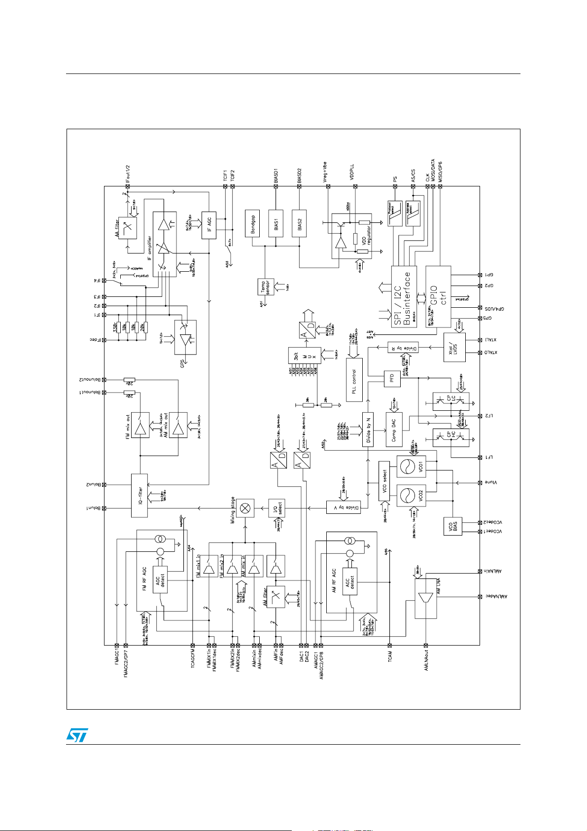
1.2 Block diagram
Figure 1. Block diagram
TDA7528
Doc ID 13141 Rev 6 9/65
Pin description TDA7528
2 Pin description
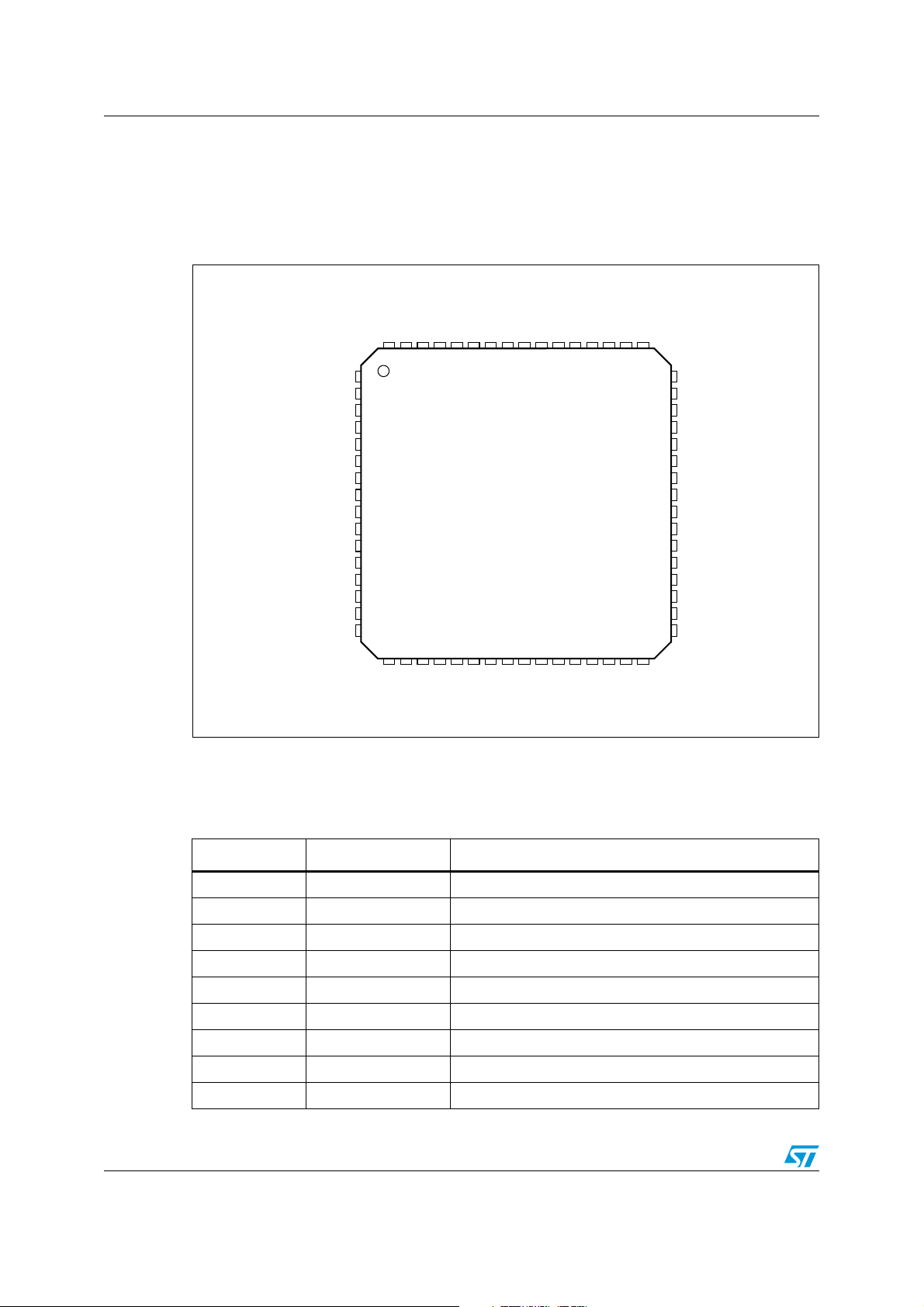
2.1 Pin connection
Figure 2. Pinout diagram (top view)
GNDRF2
GP5/IFbuff
IFin1
GP2/TCAM2
IFin2
IFin3
VCCIF
IFin4/GP3/key
IFdec
TCIF2
48
47
46
45
44
43
42
41
40
39
38
37
36
35
34
33
GNDDIF
TCIFI
IFout1
IFout2
BIASD2
VDDdec
VCCBUS
MISO
MOSI
CLK
CS/AS
PS
GNDBUS
VCCRO
XTAL0
XTAL1
Balun1
Balundec
DAC2
DAC1
FMMIX1in
FMMIX1dec
FMAGC2/GP7
FMAGC1
FMMIX2in
FMMIX2dec
GNDRF1
AMAGC1
AMMIXdec
AMMIXin
AMFdec
AMFin
BALUNout1
BALUNout2
63
64
1
2
3
4
5
6
7
8
9
10
12
13
14
15
16
17 18 19 20 21
VCCRF2
61
62
TCAM
TCFM
59 58 57 565455 53 52 51 50 49
60
22 23 24 25 26
BIASD1
271128 29 30 31 32
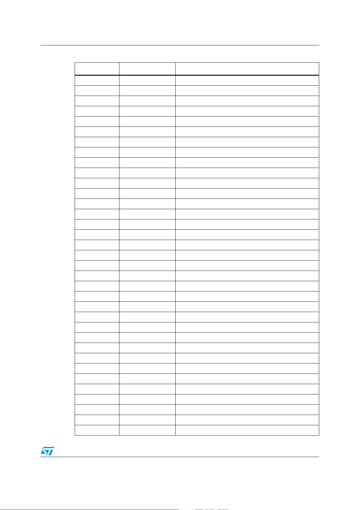
2.2 Pin description
Table 2. Pin function description
Pin # Pin name Description
1 BALUN1 Active balun input 1
2 BALUNdec Active balun input 2 (decoupling)
3 DAC2 Tuning DAC 2 output
4 DAC1 Tuning DAC 1 output
5 FMMIX1in FM mixer input – high gain stage = mode 1
6 FMMIX1dec FM mixer decouple
7 FMAGC2/GP7 FM AGC voltage output / alternative GP7 output
8 FMAGC1 FM AGC current output for PIN diode
9 FMMIX2in FM Mixer input – low gain stage = mode2
GP4/UDS
AMLNAout
AMLNAin
AMLNAgnd
AMGC2/GP8
VCCRF1
VCOdec1
Vtune
VCOdec2
VCOGND
LFLC
LFHC
VDDPLL
GNDPLL
GP1
GNDRO
TDA7528_LQFP64_PinOut
10/65 Doc ID 13141 Rev 6
TDA7528 Pin description
Table 2. Pin function description (continued)
Pin # Pin name Description
10 FMMIX2dec FM Mixer decouple
11 GNDRF1 GND RF1 section
12 AMAGC1 AMAGC PIN diode driver output
13 AMMIXdec AM mixer decouple
14 AMMIXin AM mixer input
15 AMFdec Decoupling of AM filter
16 AMFin Input of AM filter
17 AMLNAout AM LNA output
18 GP4/UDS GPIO 4 / UDS input
19 AMAGC2/GP8 AM AGC voltage output / alternative GP8 output
20 AMLNAin AM LNA input
21 AMLNAGND AM LNA Ground
22 VCCRF1 Supply RF1 section
23 VCOdec1 BIAS decouple for VCO
24 Vtune VCO tuning voltage
25 VCOdec2 BIAS decouple for VCO
26 GNDVCO VCO Ground
27 LFLC Loop filter low current output
28 LFHC Loop filter high current output
29 GNDPLL PLL Ground
30 VDDPLL Supply PLL
31 GP1 GPIO 1
32 GNDRO Ground PLL digital part
33 XTALI Reference oscillator input
34 XTALO Reference oscillator output
35 VCCRO Supply PLL digital part
36 BUSGND BUS interface Ground
37 PS Protocol Select
38 CS/AS Chip select / Address select
39 CLK SPI / I2C clock
40 MOSI SPI data input / I2C Data
41 MISO SPI data output / GP6
42 VCCBUS Supply of BUS interface
43 VDDdec Decouple of internal 3.3V (=3,3V + Vbe)
44 BIASD2 Decoupling for biasing
Doc ID 13141 Rev 6 11/65
Pin description TDA7528
Table 2. Pin function description (continued)
Pin # Pin name Description
45 IFout2 Differential IF output 2
46 IFout1 Differential IF output 1
47 TCIF1 time constant IF AGC for AM
48 GNDIF ground IF section
49 TCIF2 time constant IF AGC for FM
50 IFdec Decouple of IF amplifier
51 IFin4 / GP3 IF input 4 (= AM IBOC input) / GPIO 3
52 VCCIF Supply IF section
53 IFin3 IF input 3 (= AM analog input)
54 BIASD1 Decoupling for biasing
55 IFin2 IF input 2 (= FM IBOC input)
56 GP2/TCAM2 GPIO 2 / input for 2nd order time constant of AM AGC
57 IFin1 IF input 1 (= FM analog input)
58 GP5/IFbuff GPIO 5 / IF buffer amplifier output
59 GNDRF2 GND RF2 section = active balun GND
60 TCAM AM AGC time constant
61 TCFM FM AGC time constant
62 VCCRF2 Supply voltage RF2 section
63 Balunout1 Active balun output 1 = FM output
64 Balunout2 Active balun output 2 = AM output
12/65 Doc ID 13141 Rev 6
TDA7528 Electrical characteristics
3 Electrical characteristics
3.1 Absolute maximum ratings
Table 3. Absolute maximum ratings
Symbol Parameter Value Unit
V
V
T
CC
DD
amb
T
s
T
j
Supply voltage 5.5 V
Supply voltage 3.6 V
Ambient temperature range -40 to 125 °C
Storage temperature -55 to 150 °C
Max. junction temperature 150 °C
Operating temperature and supply voltage range: -40 °C to 105 °C; 4.7 V to 5.35 V.
All specification parameter are fulfilled in this temperature and supply voltage range, unless
otherwise specified. Typical values reflect average measurement at T
V
= 5.0 V and VDD = 3.3 V.
CC
= 25 °C,
amb
3.2 General parameters
Table 4. General parameters electrical characteristics
Symbol Parameter Test conditions Min. Typ Max Unit
V
CC
V
DD
I
CC
I
CCmax
I
CC_pwd
P
max
T
amb
T
extend
Full performance 4.7 5 5.35 V
5V supply voltage
3.3V supply voltage
V
slew rate range - 0.01 - 1000 V/ms
CC
Fully functional but with
reduced performance
When used with external
3.3 V power supply regulator
4.6 - 4.7 V
3.1 3.3 3.5 V
FM typical application - 160 200 mA
Supply current @5V typ
AM external pre-stage - 160 200 mA
AM integrated pre-stage - 175 215 mA
FM, max application,
Max supply current
(FM typ + Xtal, IF-buffer,
- 170 215 mA
AMAGC)
Supply current @5V in power
down mode
--711mA
FM typical application - 650 950 mW
Power dissipation
AM external pre-stage - 650 950 mW
AM integrated pre-stage 710 1015 mW
Ambient temperature range
Extended ambient
temperature range
Full performance, unless
otherwise specified
Signal path functional with
reduced performance
-40 - 105 °C
105 - 125 °C
Doc ID 13141 Rev 6 13/65

Electrical characteristics TDA7528
3.3 Power management and voltage regulator
The TDA7528 has a single 5 V supply. The 3.3 V supply for the VCO must be derived from
an external NPN transistor controlled by the internal voltage regulator. It is also possible to
use an external 3.3 V regulator. In this case, special care has to be taken on this 3.3V .
3.3.1 Power management
The TDA7528 detects whether all the voltages are high enough and stable when the
operating power supply is applied. The power-on reset is tripped and all the control registers
are set to "low" if this condition is not met.
As long as the voltages remain within the permissible range, the SPI/I
(in the I
2
C mode this can be detected by the μP through the acknowledge signal on every
communication with the bus master).
The SPI-/I
2
C interface is in power-on mode when the operating voltage is applied to the
TDA7528.
The following function groups can be switched on/off via SPI/I
● PLL {divider R, N and V, PFD, charge pump, VCO1 (3,7 GHz-VCO) or VCO2 (4,7 GHz-
2
C:
VCO), Reference-Oscillator or LVDS input buffer}
● FM/AM-mixer and active balun, FM-AGC
● D/A-converter_1
● D/A-converter_2
● AM-LNA
● AM-low pass filter
● AM-AGC
● IF-section {IF-amplifier, anti-aliasing-filter, IF-AGC}
● GPIO
● temperature-sensor,
● Sensor ADC
2
C interface is active
3.3.2 Power-on circuit and low supply voltage detector
Power-on circuit:
The power-on circuit produces a reset whenever one of the following voltages is below it's
POR level. (BIASD1, BIASD2 < 1.2 V; VDDPLL < 2.4V; VCCIF < 3.8 V)
Low supply voltage detector:
The "PWR_STABLE_read" status bit has the value "0" after power on. This bit is set to "1"
by an SPI/I2C write command from the microcontroller in initialization communication to the
"PWR_STABLE_write" bit. The microcontroller cannot reset the "PWR_STABLE_read" bit. A
"0" transmitted in the "PWR_STABLE_write" bit has no effect.
If the power supply falls below the programmed threshold all registers are set to their poweron default, including that the "PWR_STABLE_read" bit is set to "0". By this the
microcontroller can verify at any time whether a critical drop in voltage (value "0") has taken
place since the last TDA7528 read out of this bit. The threshold voltage can be calibrated
14/65 Doc ID 13141 Rev 6
TDA7528 Electrical characteristics
indirect by measuring the DAC1 (9 bit) output voltage for DAC1=0x200 or the DAC2 (8 bit)
output voltage for DAC2=0x100).
The PWR_STABLE functionality can be switched on/off. The default value is the switched off
mode.
Table 5. Voltage sag detection electrical characteristics
Symbol Parameter Test conditions Min. Typ Max Unit
V
STHmin
V
STHmax
Min. supply voltage threshold -40 to 150 °C, Tj ≤150 °C 4.1 4.3 4.5 V
Max supply voltage threshold - 4.4 4.6 4.9 V
- Step size - - 100 - mV
Time constant - - 1 - μs
t
c
3.3.3 Voltage regulator
The internal voltage regulator drives the external transistor for the 3.3V supply of the VCO
and PLL. The 3.3 V voltage regulator for the bus interface and the reference oscillator is fully
integrated.
Table 6. Voltage regulator electrical characteristics
Symbol Parameter Test conditions Min. Typ Max Unit
V
DD
I
DD
3.3V supply voltage
Internal voltage regulator with
external power transistor
3.1 3.3 3.5 V
Current through external
current of external V
DD
transistor or from external
-6080mA
3.3 V supply
When an external 3.3 V supply is used for the VCO and PLL supply, special care has to be
taken on the supply voltages during the ramp-up phase:
● the 3.3 V supply must never be higher than the 5 V supply;
● the difference between 5 V and 3.3 V must never exceed 3.6 V.
The second prerequisite is automatically met using a 3.3 V Z-diode between the 5 V and the
3.3 V supplies.
Doc ID 13141 Rev 6 15/65
Electrical characteristics TDA7528
3.4 FM - Section
3.4.1 IMR and active balun
The IMR mixer has two software-selectable FM inputs (referred to as mode 1 and mode 2).
These inputs are implemented with different gains, noise figures, IIP3, maximum input
signal.
There are two single ended outputs of the IMR mixer. One is dedicated to FM (Balunout1)
and the other to AM (Balunout2). It is not recommended to use both outputs in parallel.
Table 7. IMR and active balun electrical characteristics
Symbol Parameter Test condition Min. Typ Max Units
(All parameter are referred to Balunout1, unless otherwise specified)
G
G
G
G
mix1
mix2
mix1
mix2
Gain vs. Balunout1
Gain vs. Balunout1
Gain vs. Balunout2
Gain vs. Balunout2
Mode 1 (unloaded gain)
Mode 2 (unloaded gain)
Mode 1 (unloaded gain)
Mode 2 (unloaded gain)
20
13
16
9
22
15
18
11
24
17
20
13
- Absolute gain error @ 100 MHz @ 25°C - - ± 1.0 dB
Freq. range @ 25°C
- Gain error vs. frequency
47,0 to 74,0 MHz
76,0 to 90,0 MHz
87,5 to 108,0 MHz
30,0 to 170,0 MHz
--
± 0,5
± 0,5
± 0,5
± 2,0
- Gain error vs. temperature -40 °C to 105 °C - - ± 2,0 dB
- Gain attenuation range Controlled by IF-AGC 17.5 20 - dB
- Input impedance
- Input resistance
Mode 1
Mode 2
Mode 1
Mode 2
5
5
30
9.5
--kΩ
50
12.5 19.5
- Output impedance Active balun 15 20 30 Ω
- External load
V
out_max
V
in_max
Max. output voltage
Max. input voltage
Full current: reg14[5] = 0
Red. current: reg14[5] = 1
1dB below 1dB compression
point
Mode 1
Mode 2
1dB below 1dB compression
320
600
--
121 123 - dBμV
100
108
--dBμV
point
V
noise
d
noise
Input noise voltage – mode1
(1)
Input noise voltage – mode2
vnoise*atten*dnoise
Rsource=1.5 kΩ, noiseless
in 65 MHz-170 MHz range
Rsource = 800 Ω, noiseless
in 65 MHz-170 MHz range
AGC noise behavior
@ 6 dB attenuation
-
-6-dB
3.1
5
3.7
6
dB
dB
dB
kΩ
Ω
Ω
nV/√ Hz
16/65 Doc ID 13141 Rev 6
TDA7528 Electrical characteristics
Table 7. IMR and active balun electrical characteristics (continued)
(All parameter are referred to Balunout1, unless otherwise specified)
Symbol Parameter Test condition Min. Typ Max Units
Mode 1
123
125
up to Vin/tone = 90 dBµV
3rd order intercept point
Reg9[5:4]=00
Mode 2
up to Vin/tone = 98 dBµV
up to 95 °C junction
126
130
133
temperature
IIP3
IIP2
IFattn
(1)
rd
order intercept point in
3
reduced current mode
(1)
2nd order intercept point
IF- output attenuation
(without external circuitry)
Mode 1; reg14[3:2]=01 - 120 -
Mode 2; reg14[3:2]=01
60 °C up to 125 °C junction
temperature
130
132
Mode 1; reg14[3:2]=10 - 117 -
Mode 2; reg14[3:2]=10
junction temperature > 90 °C 129
Mode 1
Mode 2
@ 26.35 MHz
@ 100 MHz
144
157
1
9
130 -
--dBμV
2
- IF rejection - 38 - - dB
R
=1.5 kΩ
source
V
LO_IN
LO signal @ mixer input
@ fundamental LO freq.
--1040dBμV
@ LO harmonics
Incl. LC-tank with Q=2,
R
= 1.0 kΩ
V
LO_OUT
LO signal @ balun output
load
@ fundamental LO freq.
--
@ LO harmonics
I/Q gain adjust
I
QG
Min.
Max.
4bit - -0.7
0.7
- gain step - - 0.1 - dB
I/Q phase adjust
P
IQ
Min.
Max.
4bit - -1.2
1.2
- Phase step - - 0.2 - °
Center frequency adjust
-
Min.
Max.
3bit - -2.4
2.4
- Frequency step - - 0.6 - MHz
without gain/phase adjust 30 45 -
IRR Image rejection ratio
1. Parameter not guaranteed by production test
with freq/gain adjust @ 25°C 45 - -
with freq/gain/phase adjust
vs. complete temp. range
40 - -
-dBμV
-
dBμV
-dB
66
dBμV
60
-dB
-°
-MHz
dB
Doc ID 13141 Rev 6 17/65
Electrical characteristics TDA7528
3.4.2 FM AGC
The time constant of the FM AGC is defined by an external capacitor and the programmable
internal currents (details given in the Ta bl e 8 ). The currents can be selected independently
for AGC attack and decay. By this a symmetrical behavior rather than a 2...250 times faster
attack behavior can be programmed.
Control behavior:
The FM-RF-AGC is realized with two output pins which control the gain of the corresponding
pre-stage.
The control behavior can be programmed to the following modes:
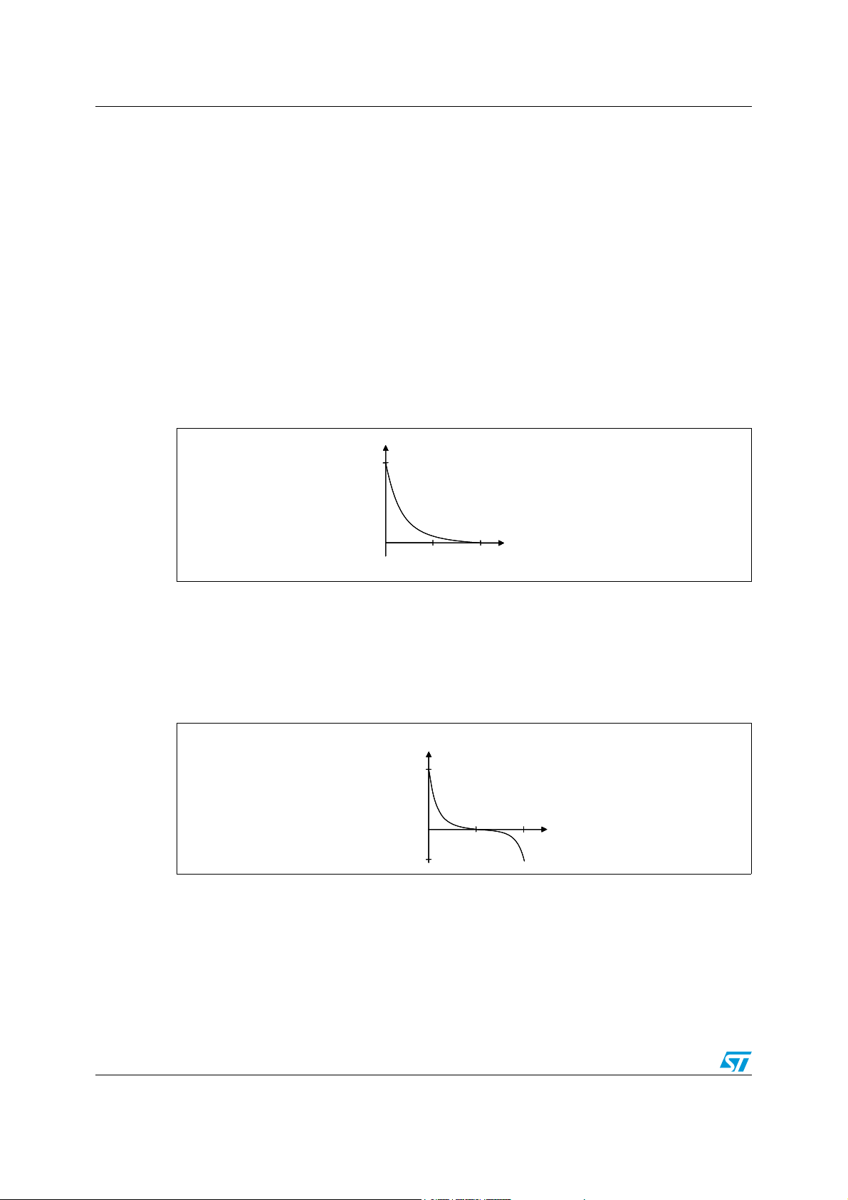
1. Controlled current output mode 1
data byte FMAGC[3:0] = 1000
positive current I = f(e): after reaching the AGC threshold voltage the current output
delivers a current I = f(e) up to -15 mA in a voltage range from 0.2V up to V
Figure 3. FM AGC - Controlled current output mode 1
Iout
Iout
15mA
15mA
f(e) current
f(e) currentf(e) current
CC
-1.5 V.
V_TCAGCFM
V_TCAGCFM
2. Controlled current output mode 2
data byte FMAGC[3:0] = 1100
Below the AGC threshold voltage the AGC output sinks a constant current of 5 mA.
When the RF input level crosses the AGC threshold voltage the current is reduced
down to 0mA with a quasi-log. behavior. At half control voltage the current becomes
positive and reaches up to -15 mA following an exponential function.
Figure 4. FM AGC - Controlled current output mode 2
Iout
Iout
Iout
f(e) - current
f(e) - current
f(e) - current
15m
15m
15m
A
A
A
1.65V
1.65V
1.65V
3. Constant current mode
data byte FMAGC[3:0] = 0100
The output current can be set to 2 mA source current. The AGC detector is in powerdown mode and only the pin diode driver is active.
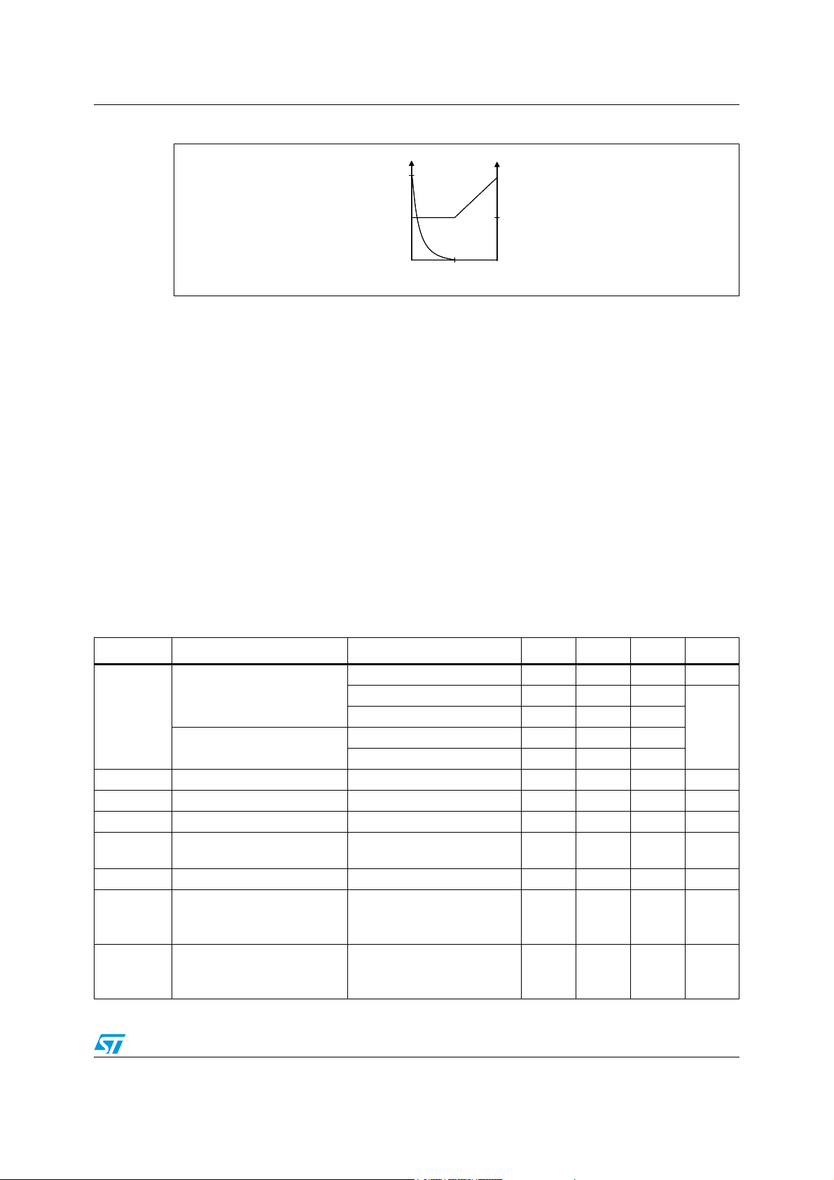
4. Controlled Voltage / current output
data byte FMAGC[3:0] = 1011
voltage and current mode with hand-over: the Vthr level is programmable in the range
of 0.2 V to 2.6 V.
18/65 Doc ID 13141 Rev 6
TDA7528 Electrical characteristics
Figure 5. FM AGC - Controlled Voltage / current output
Iout Vout
Iout Vout
Iout Vout
Vthr
Vthr
Vthr
Vthr
Vthr
5. Calibration mode
data byte FMAGC[3:0] = 0010
calibration mode for voltage output: The voltage Vthr can be switched directly to the
voltage output pin.
All other possible bit combinations of data byte FMAGC[3:0] are not recommended.
The voltage output can be configured as GPO.
The FMAGC2 output (voltage output) is short-circuit protected by a current limiter. The
FMAGC1 output (current output) needs an external resistor for current limitation. The
current output is voltage-tolerant up to V
, the voltage output up to VDD.
CC
The microcontroller can read the voltage at the AGC capacitor via the serial control
interface. On request of the microcontroller the measurement is done by applying the time
constant capacitor voltage to the central ADC (specified in chapter 3.10) and gives
information to calculate the AGC-attenuation.
The FM AGC system is controlled by a peak detector.
The Key AGC function is controlled by a D/A converter in the backend.
Table 8. FM-AGC electrical characteristics
Symbol Parameter Test condition Min. Typ Max Units
Lthr
- Threshold steps 4 bit control 0.5 1 1.5 dB
- Threshold error 30 to170 MHz @ 25 °C -1.5 - 1,5 dB
- Total threshold error 30.0 to 170.0 MHz -3 - 3 dB
-
- Frequency range - 30 - 170 MHz
-
-
Threshold RF level
Min. Threshold
Max Threshold
Temperature behavior of AGC
thresholds
Pin diode source current
(I ≈−1.5 mA * (exp(V
V
AGCTC
)-1))
DD
-
Pin diode sink current
(I ≈ 1 mA * (exp(V
AGCTC
-
1.65V)-1))
Referred to mixer input - - - -
Mode 1 - high gain mixer - 86 -
Mode 2 – low gain mixer - 92 -
Mode 1 - high gain mixer - 100 -
Mode 2 – low gain mixer - 106 -
- - 0.011 - dB/°C
AGCTC
< 1V
---10mA
V
(due to exponential behavior,
external resistor needed)
V
(due to exponential behavior,
AGCTC
= V
DD
3--mA
external resistor needed)
dBμV
Doc ID 13141 Rev 6 19/65
Electrical characteristics TDA7528
Table 8. FM-AGC electrical characteristics (continued)
Symbol Parameter Test condition Min. Typ Max Units
-
-Min. voltage
- Max. voltage AGC control pin 1 V
- Max. source current
- Min. sink current
-
-
Vthr
Vthr
- Step size of Vthr 6bit - 40 - mV
DNL nonlinearity of Vthr - -0.5 0.5 LSB
- I attack for 6dB control error
- I decay max
-
-
- Threshold shift keyed AGC
- Keyed AGC range - 10 - - dB
1. The time constant is defined as the 1τ value after a 6 dB level step
Pin diode source current in
constant current mode
- - -2 -1 mA
AGC control pin 1
@ positive current mode
--0.2
@ pos/neg current mode
-1.5 VCC-1.3 - V
CC
AGC control pin 2;
voltage output
AGC control pin 2;
voltage output
Max. output voltage in analog
voltage mode (follower mode)
Min. output voltage in analog
voltage mode
Vthr_min - 0.1 0.2 0.3 V
min
Vthr_max - 2.4 2.6 2.8 V
max
AGC control pin 2
= 1 mA
@ I
load
AGC control pin 2
= -50 µA
@ I
load
Mode A1
Mode A2
Mode A3
Mode D1
Mode D2
Mode D3
Typical AGC time constant for
(1)
attack
Typical AGC time constant for
(1)
decay
C
AGC conductance versus
V
C
AGC conductance versus
V
= 1 µF, mode A2
AGCTC
= 20 dB/V
AGCTC
= 1 µF, mode D2
AGCTC
= 20 dB/V
AGCTC
Control input range = 0.2 to
1V
1--mA
- -100 - μA
VDD-0.3 - V
--1V
30
150
0.75
-6
-30
-150
50
250
1.25
-4
-20
-100
-0.5-ms
-15-ms
-19-dB/V
0.4
DD
80
400
2.0
-2.5
-12
-60
V
V
µA
µA
20/65 Doc ID 13141 Rev 6

TDA7528 Electrical characteristics
3.5 AM - Section
3.5.1 AM LNA
Table 9. AM LNA electrical characteristics
Symbol Parameter Test condition Min. Typ Max Units
gm Transconductance @ 25°C 10 15 20 mS
Freq. range
- Gain error vs. frequency
150 to 350 kHz
520 to 1710 kHz
2.0 to 30.0 MHz
0.05 to 30.0 MHz
--
± 0.5
± 0.5
± 1.0
± 2.5
- Input impedance - 500 1000 kΩ
(1)
vnoise
(1)
IIP3
IIP2 2
Input noise voltage
@ 1 MHz
@ 150 kHz
-
3rd order intercept point @ gain 20 dB 123 128 - dBμV
nd
order intercept point @ gain 20 dB 127 132 - dBμV
1.7
2.6
2
AGC AGC range - 8 - - dB
1. Parameter not guaranteed by production test
3.5.2 Switchable LPF 4th order
Table 10. Switchable LPF 4th order electrical characteristics
Symbol Parameter Test condition Min. Typ Max Units
f
LP1
f
LP2
f
LP3
f
LP4
f
LP5
G Gain incl. mix vs. Balunout1 - 3 4.5 6 dB
G Gain incl. mix vs. Balunout2 - -1 0.5 2 dB
- Passband ripple
LP corner frequency 1 Mode 1
LP corner frequency 2 Mode 2
LP corner frequency 3 Mode 3
LP corner frequency 4 Mode 4
LP corner frequency 5 Mode 5
(2)
-----
(1)
(1)
(1)
(1)
(1)
1.71 - 1.95 MHz
6.2 - 7.1 MHz
14.0 - 16.0 MHz
22.0 - 25.5 MHz
26.1 - 31.0 MHz
dB
nV/√ Hz
- Stop band attenuation
Mode=1 @ 10.7 MHz
( L W + M W ) @ > 2 2 M H z
Mode=2 @ >28 MHz
(KW low) @ >87.5 MHz
Mode=3 @ >43 MHz
(KW mid) @ >87.5 MHz
Mode=4 @ >74 MHz
(KW high) @ >87.5 MHz
Mode=5 @ >74 MHz
(11m) @ >87.5 MHz
40
60
30
60
20
45
25
30
20
25
--dB
Doc ID 13141 Rev 6 21/65

Electrical characteristics TDA7528
Table 10. Switchable LPF 4th order electrical characteristics (continued)
Symbol Parameter Test condition Min. Typ Max Units
Vnoise
IIP3 3
IIP2
1. Corner frequency needs calibration
2. Parameter not guaranteed by production test
noise
rd
order intercept point Up to 10 MHz input frequency 137 140 - dBμV
(2)
2nd order intercept point Up to 10 MHz input frequency 160 - - dBμV
Input noise voltage incl. IMR
(2)
@ 1 to 30 MHz, @ 25°C
@ 0.15 to 1 MHz, @ 25°C
-
30
33
34
37
3.5.3 IMR and active balun
All parameter are referred to Balunout2, unless otherwise specified
Table 11. IMR and active balun electrical characteristics
Symbol Parameter Test condition Min. Typ Max Units
GGain
- Gain error @ 1 MHz --> 10.7MHz - - ± 1.0 dB
- Gain Error vs. frequency
vs. Balunout2 7 9 11 dB
vs. Balunout1 111315dB
freq. range
150 to 350 kHz
520 to 1710 kHz
2.0 to 30.0 MHz
0.05 to 30.0 MHz
--
± 0,5
± 0,5
± 1.0
± 2,0
nV/√ Hz
dB
- Gain error vs. temperature –40°C to 105 °C - - ± 2,0 dB
- Gain attenuation range IFAGC controlled 17.5 20 dB
- Input impedance For ext. LNA input 9.2 11.8 17.2 kΩ
- Output impedance - 15 20 30 Ω
- Max. external load - 400 - - Ω
Vmax Max. output voltage
Vin_max Max. input voltage
1 dB below 1 dB compression
point
Single tone
two tone
121 123 - dBμV
101
98
--
@4.6 V-4.7 V
Vin_max Max. input voltage
(1)
vnoise
IIP3
Input noise voltage @ full gain 150 kHz-30 MHz 5.8 7.0 nV/√ Hz
(1)
3rd order intercept point
single tone
two tone
@ full gain Reg14[5:4] = 00
up to 95 °C junction
99
96
128
131
--dBμV
134
-dBμV
temperature
dBμV
dBμV
dBμV
22/65 Doc ID 13141 Rev 6

TDA7528 Electrical characteristics
Table 11. IMR and active balun electrical characteristics (continued)
Symbol Parameter Test condition Min. Typ Max Units
133
132
-dBμV
-dBμV
IIP2
Reg14[5:4] = 01
-
3rd order intercept point in
reduced current mode
temperature
60 °C up to 125 °C junction
131
Reg14[5:4] = 10
junction temperature > 90 °C 131
(1)
2nd order intercept point - 159 - - dBμV
- IF-output attenuation @ 26.35 MHz 1 - - dB
- IF rejection - 40 48 - dB
R
=1.5 kΩ
source
@ fundamental LO freq
--1030dBμV
V
LO_IN
(1)
LO signal @ mixer input
@ harmonics of LO freq.
Incl. LC-tank with Q=2,
= 1.0 kΩ
R
V
LO_OUT
LO signal @ balun output
using mixer input
load
@ fundamental LO freq.
with 1 kΩ input termination
resistor
(1)
@ harmonics of LO freq.
--
95
80
66
Incl. LC-tank with Q=2,
LO signal @ balun output,
using low pass filter
Rload=1.0 kΩ
@ fundamental LO freq.
@ harmonics of LO freq.
-85
66
I/Q gain adjust
I
QG
Min.
Max.
4 bit - -0.7
0.7
-dB
dBμV
- Gain step - - 0.1 - dB
I/Q phase adjust
PIQ
Min.
Max.
4bit - -0.25
0.25
- phase step - - 0.25 - °
Center frequency adjust
-
Min.
Max.
3bit - -2.4
2.4
- Frequency step - - 0.6 - MHz
IRR Image rejection ratio Without gain/phase adjust 30 45 - dB
IRR Image rejection ratio
IRR Image rejection ratio
1. Parameter not guaranteed by production test
With gain/phase adjust @
25°C
With gain/phase adjust vs.
complete temp. range
45 - - dB
40 - - dB
Doc ID 13141 Rev 6 23/65
-°
-MHz

Electrical characteristics TDA7528
3.5.4 AM AGC
The time constant of the AM AGC is defined by an external capacitor and the programmable
internal currents (details given in the Ta bl e 1 2).
Control behavior:
The AM RF AGC is realized with two output pins which controls the gain of the
corresponding pre-stage.
The control behavior can be programmed to the following modes:
1. Controlled current output mode 1
data byte AMAGC[3:0] = 1000
positive current I = f(e): after reaching the AGC threshold voltage the current output
delivers a current I = f(e) up to 15 mA in a voltage range from 0.1 V up to V
Figure 6. AM AGC - Controlled current output mode 1
Iout
Iout
Iout
15mA
15mA
15mA
f(e) current
f(e) current
f(e) current
CC
-1.5 V.
V_TCAGCAM
V_TCAGCAM
2. Constant current mode
data byte AMAGC[3:0] = 0100
constant current mode: the output current can be set to 2 mA source current. The AGC
detector is in power-down mode and only the pin diode driver is active.
3. Voltage and current mode with hand-over
a) internal feedback
data byte AMAGC[3:0] = 1001
voltage and current mode with hand-over: the Vthr level is programmable in the
range 1 V to 2.6 V.
This mode can be used in combination with both the internal and the external
LNA. In combination with the internal AM LNA, the maximum output voltage is
limited to 2.7 V.
Figure 7. AM AGC - Voltage and current mode with hand-over
Iout Vout
Iout Vout
Vthr
Vthr
Vthr
Vthr
b) external feedback
data byte AMAGC[3:0] = 1011
Voltage and current mode with hand-over: the Vthr level is programmable in the
range 0.2 to 2.6 V. The voltage Vthr is the internal reference voltage for the
24/65 Doc ID 13141 Rev 6

TDA7528 Electrical characteristics
external feedback to pin GP4/UDS. This mode can only be used with an external
LNA.
4. Calibration mode for voltage output
a) internal feedback
data byte AMAGC[3:0] = 1110
calibration mode for voltage output (mode 3.a.): the voltage Vthr can be switched
directly to the voltage output pin. The reference voltage is programmable in the
range described in 3.a.
b) external feedback
data byte AMAGC[3:0] = 0010
calibration mode for external feedback (mode 3.b.): the output voltage is set to a
value, that the feedback on GP4(UDS is equal to Vthr. The reference voltage is
programmable in the range described in 3.b.
All other possible bit combinations of data byte AMAGC[3:0] are prohibited.
The voltage output can be configured as GPO.
The AMAGC2 output (voltage output) is short-circuit protected by a current limiter. The
AMAGC1 output (current output) needs an external resistor. The current output is voltagetolerant up to VCC, the voltage output up to VDD.
The microcontroller (STA3005 backend) can read the voltage at the AGC capacitor via the
serial control interface. On the microcontroller request, the measurement is done by
connecting the time constant capacitor to the central ADC (specified in chapter 3.10); the
information can be used to calculate the AGC attenuation.
The AM AGC system is controlled by an average detector.
The AM AGC can be enabled independently in AM and FM mode
Table 12. AM-AGC electrical characteristics
Symbol Parameter Test condition Min. Typ Max Units
Lthr
- Threshold steps 4 bit control 0.4 0.9 1.4 dB
- Absolute threshold error 0.5 to 30.0 MHz @ 25 °C -1 - 2 dB
- Total threshold error 0.5 to 30.0 MHz -2 - 3 dB
- Absolute threshold error 0.1 to 0.5 MHz @ 25 °C -0.5 - 3 dB
- Total threshold error 0.1 to 0.5 MHz -2 - 3.5 dB
Threshold RF level
Min. Threshold
Max Threshold
Referred to mixer input - - - -
AM mixer input - 89 - dBµV
AM filter input - 94 - dBµV
AM mixer input - 101.5 - dBµV
AM filter input - 106.5 - dBµV
-
- Frequency range Reduced performance 0.05 - 0.1 MHz
- frequency range - 0.1 - 30 MHz
Temperature drift of AGC
thresholds
- - 0.011 - dB/°C
Doc ID 13141 Rev 6 25/65

Electrical characteristics TDA7528
Table 12. AM-AGC electrical characteristics (continued)
Symbol Parameter Test condition Min. Typ Max Units
Pin diode source current
-
(I ≈ 1.5 mA * (exp(V
V
AGCTC
)-1))
DD
-
AGC control pin 1
AGCTC
< 1 V
V
external resistor necessary
---10mA
- Min. voltage AGC control pin - - 0.2 V
-
Pin diode source current in
constant current mode
- - -2 -1 mA
- Max. voltage AGC control pin 1 VCC-1.5 VCC-1.3 V
- Max. source current
- Min. sink current
-
-
Vthr
Vthr
Max. output voltage in analog
voltage mode (follower mode)
Min. output voltage in analog
voltage mode
Vthr_min - 0.1 0.2 0.3 V
min
Vthr_max - 2.4 2.6 2.8 V
max
AGC control pin 2;
voltage output
AGC control pin 2;
voltage output
AGC control pin 2
= 1 mA
@ I
load
AGC control pin 2
= -50 µA
@ I
load
- - -1 mA
90 - - µA
VDD-0.3 - V
DD
--1V
- Step size of Vthr 6 bit 40 mV
DNL Nonlinearity of Vthr - -0.5 0.5 LSB
-
TC current for 6 dB control
error
Mode T1
Mode T2
Mode T3
2.5
12
60
4
20
100
6.5
32
160
V
µA
-
I attack in fast attack mode
@ 10 dB control error
- Typical AGC time constant
1. The time constant is defined as the 1τ value, means when the AGC is settled to 63% after a 6dB step
Active if control deviation is
more than 7 dB
C
(1)
AGC conductance versus
V
= 1µF, mode T2
AGCTC
= 20 dB/V
AGCTC
0.9 1.7 2.3 mA
-15-ms
26/65 Doc ID 13141 Rev 6

TDA7528 Electrical characteristics
3.6 IF - Section
3.6.1 IF-Amplifier
Table 13. IF-Amplifier with anti aliasing filter and ADC buffer electrical characteristics
Symbol Parameter Test condition Min. Typ Max Units
Gain
Min. programmable gain
Max programmable gain
Input 1-3 (FM,HD,AM)
Input 4 (HD-Radio AM)
Input 1-3 (FM,HD,AM)
Input 4 (HD-Radio AM)
23
-
16
37
-dB
30
Gstep Gain step 3 bit control 1 2 3 dB
Minimum gain of IF-Amplifier
Gmin
in AGC mode
Input 1-3
Input 4
Gerr Gain error
Full AGC reaction
< 1V 14
V
TCIF
@ 10.7 MHz, AAfilt<1:0>
=10
17
7
10
19
12
-2 - 2 dB
with AAfilt<1:0> = 00 -4 - 2 dB
f
cut
f
cut_cal
-
Cut off frequency without
calibration
Cut off frequency after
calibration
Stop band attenuation with
calibration
-3 dB without calibration 10 15 21 MHz
-3 dB with calibration 13 15 17 MHz
@ 26.35 MHz
@ 47.75 MHz
15
30
--dB
- Pass band ripple @ 400kHz bandwidth - - 0.5 dB
Rin_input1 Input impedance input 1 FM –input 265 330 400 Ω
Rin_input2 Input impedance input 2 HD-Radio FM input 5.5 10 18 kΩ
Rin_input3 Input impedance input 3 AM input 5.5 10 18 kΩ
Rin_input4 Input impedance input 4 HD-Radio AM input 11 20 34 kΩ
Vout_max Max. output voltage R
(1)
IIP3
(1)
OIP3
(1)
IIP2
Vnoise_input 1
Vnoise_input 2
3rd order intercept point
3rd order intercept point
2nd order intercept point
Input noise voltage @ 330 Ω
(1)
input
Input noise voltage @ 3.3 kΩ
(1)
input
≥180 Ω 117 - - dBµV
L
Input stage 1-3
Input stage 4
120
128
125
132
-dBµV
Up to 116 dBµV output
voltage, without AGC
attenuation, R
≥180 Ω
L
Input stage 1-3
input stage 4
142 145 - dBµV
147
157
--dBµV
@ source impedance
330 Ω noiseless, @31 dB
-3.54.2nV/√ Hz
gain
@ source impedance
470 Ω noiseless, @ 31 dB
-3.84.6nV/√ Hz
gain
dB
Doc ID 13141 Rev 6 27/65

Electrical characteristics TDA7528
Table 13. IF-Amplifier with anti aliasing filter and ADC buffer electrical characteristics (continued)
Symbol Parameter Test condition Min. Typ Max Units
@ source impedance
Input noise voltage @ 10 kΩ
Vnoise_input 3
Vnoise_input 4
(1)
input
Input noise voltage @ 10kW
(1)
input
Iout,max Max. output current With resistive load 4 - - mA
Zout Output impedance - - 20 40 Ω
-
1. Parameter not guaranteed by production test
Isolation between different IF
input ports
(1)
2.2 kΩ noiseless,@31 dB
gain, with external 2.7 kΩ
-56nV/√ Hz
input termination resistor
@ source impedance
2.2 kΩ noiseless, @
24 dB gain, with external
-7.58.5nV/√ Hz
2.7 kΩ input termination
resistor
@ Input impedance 2.5kΩ 30 - - dB
28/65 Doc ID 13141 Rev 6

TDA7528 Electrical characteristics
3.6.2 IF-AGC
The IF AGC system is controlled in AM with an average detector and in FM with a peak
detector.
The time constant is defined with two external capacitors and programmable internal
currents (details given in the table below).
The microcontroller can read the voltage at the AGC capacitor via the serial control
interface. On request of the microcontroller the measurement is done by applying the time
constant capacitor voltage to the central ADC (specified in chapter 3.10) and gives
information to calculate the AGC-attenuation.
Table 14. IF-AGC electrical characteristics
Symbol Parameter Test condition Min. Typ Max Units
AGC threshold IF level
Referred to differential output of
ADC buffer
----
FM - 105 - dBµV
Min. AGC threshold
Lthr
AM - 99 - dBµV
FM, Max. recommended AGC
threshold 115 dBµV
-119-dBµV
Max AGC threshold
AM, Max. recommended AGC
threshold 109 dBµV
-113-dBµV
- Threshold steps 3 bit 1.5 2 2.5 dB
- Absolute threshold error
- Total threshold error
- Temp drift of AGC threshold
10.7 MHz @ 25 °C (up to
117 dBµV output voltage)
10.7 MHz (up to 117dB µV
output voltage)
FM-mode
AM mode
-1 - 1 dB
-2.5 - 2.5 dB
0.008
-
0.0
- IF gain deviation Remaining gain control error - - 1 dB
- Fast attack mode in AM-mode
Active if control deviation is
more than 7dB
0.3 0.5 1 ms
With external 2.2 µF capacitor,
(1)
Time constant in AM mode
-
symmetric behavior (attack =
decay)
IF gain = 31 dB input 1-3; 24 dB
input4
mode S1 (slow)
mode S2 (fast)
55
5.5
110
11
With external 220 nF capacitor,
IF gain = 31 dB input1-3; 24 dB
(2)
Time constant in FM mode
asymmetric behavior
1. The AGC time constant for AM is the 1τ value, means when the AGC is settled to 63% after a 6dB step
2. The AGC time constant for FM is the time needed to settle the AGC to 90% for a 6dB level step
input4
decay mode U1 / U2
attack mode U1 (slow)
attack mode U2 (fast)
7
150
30
15
300
60
220
22
32
600
120
dB/°C
ms
ms
ms
µs
µs
Doc ID 13141 Rev 6 29/65

Electrical characteristics TDA7528
3.6.3 IF buffer amplifier
The IF buffer amplifier is a programmable, single ended amplifier. The input for the IF buffer
amplifier can be selected by software between IFin1 and IFin2. The output of the amplifier is
multiplexed with GPIO5
Table 15. IF buffer amplifier electrical characteristics
Symbol Parameter Test condition Min. Typ Max Units
Gmin Min. gain
Gmax Max. gain
Series resistance 220 Ω,
terminated with 330 Ω
Series resistance 220 Ω,
terminated with 330 Ω
--11- dB
-3- dB
Gstep Gain step 3bit - 2 - dB
- Absolute gain error - -3 3 dB
- Relative gain error Step by step -1.5 1.5 dB
(1)
vnoise
IIP3
Input noise voltage @ 10.7 MHz, 3 dB gain - 8.5 15 nV/√ Hz
(1)
3rd order intercept point
@ gain 3 dB,Vout=1 Vpp
with 500 Ω ≤ R
≤ 600 Ω
L
115 120 - dBµV
- 3 dB bandwidth - - 50 - MHz
- Output DC voltage - 1.6 - 2.1 V
- External output load - 400 550 1000 Ω
- Output impedance - 80 140 250 Ω
1. Parameter not guaranteed by production test
3.7 Phase Locked Loop
Table 16. Phase Locked Loop electrical characteristics
Parameter Test condition Min. Typ Max Units
Δf < 0.01 %
= 300 kHz
@ f
PFD
Settling time FM
(1)
fractional mode, with loop filter
according application schematic
= 100 kHz
@ f
PFD
integer mode
VCC = 4.6 – 4.7V, f
= 300kHz, loop
PFD
filter according application schematic
= 100 kHz
f
PFD
-
300
300
500
500
600
500
600
Suppression of spurious with
Spurious suppression
compensation DAC
low current charge pump
520 -dB
50 µA ≤ Icp ≤ 750 µA
1. Parameter not guaranteed by production test, depends on loop filter circuitry and CP current settings. For further
information see application note information
30/65 Doc ID 13141 Rev 6
µs
µs

TDA7528 Electrical characteristics
3.7.1 VCO
Table 17. VCO electrical characteristics
Symbol Parameter Test condition, comments Min. Typ Max Units
Tuning range, incl. switch
f
Frequency range VCO1
osc
Frequency range VCO2
between upper and lower range
0.2 V ≤ V
tune
≤ 4.2 V
Tuning range, incl. switch
between upper and lower range
0.2 V ≤ V
tune
≤ 4.2 V
4480 - 4970 MHz
3430 - 4010 MHz
At any LO frequency between
55.1 MHz and 118.7 MHz, VCO
free running, NV=8 (VCO2),
NV=10 (VCO1)
- Phase Noise of LO
@ 10 Hz
@ 100 Hz
@ 1 kHz
@ 10 kHz
@ 100 kHz
--40
-60
-86
-106
-126
-
At any LO frequency between
10.7 MHz and 40.0 MHz VCO
free running NV=25 (VCO2),
NV=30 (VCO1)
Phase Noise of LO
-
min. requirements for
AM,DRM
@ 1 Hz
@ 10 Hz
@ 100 Hz
@ 1 kHz
@ 10 kHz
@ 100 kHz
-
-33
-40
-
-80
-90
-100
-120
FM reception, deem phase
50µs, f
=20 Hz to 20 kHz @
NF
min. VCO frequency NV=8
- Deviation error
(1)
- KVCOmax/KVCOmin
Power supply ripple rejection
(1)
PSRR
V
VCO_OUT
1. Parameter not guaranteed by production test
2. Adaptation of low current CP values needed
3. With appropriate loop filter circuit
ratio
(1)
VCO signal emission
(VCO2), NV=10 (VCO1)
f
PFD
=300 kHz
(2)
, loop filter
according application
schematic
f
PFD
=1.9 MHz
(3)
For tuning voltage range
0.2 V – 4.2 V
-
8
8
-57-
-20--dB
@ tuning voltage input,
1 kΩ load
- - 60 dBµV
dBc
Hz
dBc
Hz
Hz
Doc ID 13141 Rev 6 31/65

Electrical characteristics TDA7528
3.7.2 Reference oscillator / reference frequency input buffer
Table 18. Reference oscillator / reference frequency input buffer electrical characteristics
Parameter Test condition, comments Min. Typ Max Units
Reference oscillator mode – fundamental crystal
Oscillation frequency Fundamental mode - 74.1 - MHz
Phase noise
Frequency stability
@ 1 Hz
@ 10 Hz
@ 100 Hz
@ 1 kHz
@ 10 kHz
@ 100 kHz
@ 1 MHz
Degradation generated by the
oscillator
-
-20 - 20 ppm
-20
-50
-80
-110
-130
< -130
< -130
dBc
dBc
dBc
-
dBc
dBc
dBc
dBc
Single ended input
Input frequency - - - 75 MHz
Input voltage range Single ended mode 200 - 1000 mV
Input impedance Single ended mode 10 - - kΩ
Reference frequency input buffer mode
reference input frequency differential input 0.1 - 150 MHz
max input voltage high - - - 1475 mV
min. input voltage low - 925 - - mV
Input differential voltage - 247 - 454 mV
Input offset voltage - 1125 - 1275 mV
input impedance - 150 - - kΩ
PP
3.7.3 Divider
The mixer divider V is followed by a division-by-4-stage that generates 0°/90°/-90° LO
signals for the IMR mixer (90°/-90° mode to switch between upper or lower sideband
suppression in the IMR).
The main divider N can be operated in integer mode or in fractional mode. Three fraction
factors are programmable: 2, 3 and 6. A fractional compensation circuit is located at the
charge pump. The compensation acts for the low current only.
Table 19. Divider electrical characteristics
Symbol Parameter Test condition, comments Min. Typ Max Units
Mixer divider V – integer values
N
Main divider N – fractional 2, 3 and 6 / integer divider
N
Reference divider R – integer values
N
32/65 Doc ID 13141 Rev 6
V
N
R
Divider value divider_V 7 bit 5 - 131 -
Divider value divider_N 22bit (32/33 pre scaler) 1024 - 4194304 -
Divider value divider_R 16 bit 1 - 65535 -

TDA7528 Electrical characteristics
3.7.4 Phase frequency detector and charge pump
Table 20. Phase frequency detector and charge pump electrical characteristics
Symbol Parameter Test condition Min. Typ Max Units
PFD
f
PFD
PFD input frequency - 2 - 3000 kHz
Charge pump
I
sink
I
source
Sink current
fractional compensation only
for low current modes
(bit 5 – bit 8)
Source current
fractional compensation only
for low current modes
(bit 5 – bit 8)
High current mode bit1
high current mode bit2
High current mode bit3
High current mode bit4
Low current mode bit1
Low current mode bit2
Low current mode bit3
Low current mode bit4
Low current mode bit5
High current mode bit1
high current mode bit2
High current mode bit3
High current mode bit4
low current mode bit1
Low current mode bit2
Low current mode bit3
Low current mode bit4
Low current mode bit5
-
-
-0.65
-1,3
-2,5
-4,6
-65
-130
-260
-520
-980
0.65
1.3
2.5
4.6
65
130
260
520
980
-
-
mA
mA
mA
mA
µA
µA
µA
µA
µA
mA
mA
mA
mA
µA
µA
µA
µA
µA
- Current error - - - ±30 %
V
OH
V
OL
Output voltage high - VCC-0.3 - V
CC
Output voltage low - -0.05 - 0.15 V
3.8 Temperature sensor
Table 21. Temperature sensor electrical characteristics
Temperature range - -40 - 150 °C
Resolution
Absolute error - - - ±15 °C
Relative error No direct measurement possible - 0.5 - LSB
1. Not guaranteed by production test
Parameter Test condition Min. Typ Max Units
(1)
°C / LSB (no direct measurement
possible)
4.5 5.1 5.7 °C
Doc ID 13141 Rev 6 33/65
V

Electrical characteristics TDA7528
3.9 D/A-converter
The TDA7528 contains two D/A-Converters for tuning the filters of the FM pre-stage. The
converter 1 has a resolution of 8 bit; converter 2 has a resolution of 9 bit.
Table 22. D/A-converter electrical characteristics
Symbol Parameter Test condition Min. Typ Max Units
Output voltage
V
out
minimum voltage
Maximum voltage - V
Unloaded output -
CC
0.6 0.8
-0.15 VCC-0.1 -
V
- Output impedance - - 2 - kΩ
- Max. output current - 400 - - μA
-
-
-
Average voltage step
converter 1
Average voltage step
converter 2
Additional error vs.
temperature
Resolution 8 bit - 18 - mV
Resolution 9 bit - 9 - mV
--2-2LSB
-INL - -2 - 2LSB
-DNL - -0.5 - 0.5LSB
- Output noise @ C
-Conversion time @ C
VSRR
Supply voltage ripple rejection
ratio
=1nF and 2.2kΩ -100200μV
L
=1nF - 20 40 μs
L
@ 1kHz 20 - - dB
34/65 Doc ID 13141 Rev 6

TDA7528 Electrical characteristics
3.10 A/D-converter
The TDA7528 contains a 6bit SAR A/D-Converter for sensing several analog values of the
tuner. The following analog sources can be switched to the ADC input by software
command:
● Temperature sensor
● TCFM
● TCAM
● TCIF1/2 (depends on which one is active)
● VCO tuning voltage (=3/5 * Vtune)
● GP1
● GP2
● Internal VCC divider (2/5 * VCC)
The ADC is clocked by an integrated RC-oscillator, or the PLL reference frequency.
Table 23. A/D-converter
Symbol Parameter Test condition, comments Min. Typ Max Units
- INL Referred to internal VDD -2 - 2 LSB
- DNL - -0.5 - 0.5 LSB
- Input voltage range - 0 - V
f
Osc
Oscillation frequency
2bit programmable
RCfreq<1:0> = 00
RCfreq<1:0> = 01
RCfreq<1:0> = 10
RCfreq<1:0> = 11 1.72
0.68
1.31
1.9
2.5
- frequency error - - - ±40 %
t
ADC
1. With RC-oscillator frequency = 2.5MHz
Conversion time
(1)
12 clock cycles - - 7 µs
DD
-
V
MHz
MHz
MHz
MHz
Doc ID 13141 Rev 6 35/65

Electrical characteristics TDA7528
3.11 GPIO - general purpose I/O interface pins
The TDA7528 has eight GPIO - general purpose - control pins (GP1...GP8) to switch
external stages (output), e.g amplifiers, or to read the status of external stages (input), e.g.
control voltages. Some control pins are multiplexed with other functions that are not
necessary in every tuner design.
Table 24. GPIO - general purpose I/O interface pins electrical characteristics
Pin name
GP1 3,3V 1 mA 0V 1 mA Analog input A/D-converter 0 ... 3,3V
GP2 3,3V 1 mA 0V 1 mA Analog input A/D-converter 0 ... 3,3V AMAGC 2nd TC input
GP3 3.3V 0.1 mA 0V 10 mA - - FM key AGC input
GP4 3.3V 0.1 mA 0V 10 mA - - AM cascode U
GP5 3,3V 1 mA 0V 1 mA Digital Input 0 / 3,3V IF buffer output
GP6 3,3V 1 mA 0V 1 mA Digital Input 0 / 3,3V SPI MISO output
GP7 3,3V 1 mA 0V 1 mA - - FM-AGC voltage output
GP8 3,3V 1 mA 0V 1 mA - - AM-AGC voltage output
Table 25. GPIO test conditions
High level output voltage @ 100kΩ load to GND V
Low level output voltage @ 100kΩ load to V
High level source current
High level source current
Low level sink current
Low level sink current
Input impedance digital input mode 100 - kΩ
Input voltage range GP1 / GP2 0 - 3.5 V
High level input voltage GP5 / GP6 used as digital input 2.2 - 3.5 V
Low level input voltage GP5 / GP6 used as digital input -0.05 - 1.0 V
GPIO functionality
GPIO-output GPIO-input
High level Low level
voltage
Source
current
voltage
Sink
current
Functionality voltage
Multiplexed
functionality details
are given in the
corresponding
chapters
input
DS
Parameter Test condition Min. Typ Max Units
DD
GP1 / GP2 / GP5 … GP8:
@ 1kΩ load to GND
GP3 / GP4
@ 1kΩ load to GND
GP1 / GP2 / GP5 … GP8:
@ 1kΩ load to V
DD
GP3 / GP4:
@ 100Ω load to V
8.0 10
DD
-0.3 - V
DD
DD
-0.05 - 0.3 V
0.5 1 - mA
0.08 0.25 - mA
0.8 1.5
-
-
V
mA
mA
3.11.1 Serial data interface
The TDA7528 features a serial data port for communication with the microcontroller. It is
used to program the TDA7528 and to convey the read-out values of its detectors. This port
supports data communication using the SPI and the I
36/65 Doc ID 13141 Rev 6
2
C protocols.

TDA7528 Electrical characteristics
Pin configuration of the serial data interface:
Table 26. Pin configuration of the serial data interface
Signal # Pin SPI signal Pin I2C signal
2
Signal 1 PS Protocol Select SPI/I
C PS Protocol Select SPI/I2C
Signal 2 CS Chip Select AS Address Select
Signal 3 CLK Clock CLK Clock
Signal 4 MOSI Master Out – Slave In DATA bidirectional Data
Signal 5 MISO Master In – Slave Out GP6 General Purpose Out
The "PS"-pin (Protocol Select) determines which communication protocol is used for
communication between the microcontroller and the TDA7528. The information is not latched,
so any level change at this pin immediately affects the protocol used by the TDA7528.
(a)
3.11.2 Communication using the I2C protocol
For I2C communication, pin "PS" needs to be open. Pin "AS" (Address Select) determines
which I
2
C address or group of addresses (see below) is used for communication between
the microcontroller and TDA7528. Three different external connections are defined to
represent three groups of addresses. The information is not latched, so any level change at
this pin immediately affects the address used by the TDA7528.
(b)
a. Protocol changes are not permitted during a communication sequence unless the I2C STOP condition is
established or in SPI mode the CS line is deactivated, because the consequences are not predictable. Usually
there is no need for any protocol change during operation, so the PS pin is connected to either GND or left open
b. Address changes are not permitted during an I2C communication sequence unless the I2C STOP condition is
established, because the consequences are not predictable. Usually there is no need for any address change
during operation, so the AS pin is connected to either GND, an 20k pull down resistor or left open.
Doc ID 13141 Rev 6 37/65

Electrical characteristics TDA7528
I2C addresses
Table 27. I2C addresses
Tuner: Tuner 3 Tuner 2 Tuner 1
”AS”-pin connection open 20k +/- 50% pull down GND
address: 1100 1xxd 1100 x1xd 1100 xx1d
MSB ... LSB - - 1100 000d - - 1100 001d - - R / W
1100 010d - R / W 1100 011d - W W
1100 100d R / W - 1100 101d W - W
1100 110d W W 1100 111d W W W
x = must be "0" for reading, can be "1" or "0" for writing to the TDA7528
d = determinates the direction of data transfer, reading or writing
R / W = indicates the address to write to and/or to read from a TDA7528
W = indicates those addresses that can be used to transmit equal data to several TDA7528s, e.g. to
program an synchronous AF jump of two tuners. A read out has no purpose for these addresses.
3.11.3 Communication using the SPI protocol
For SPI communication, pin "PS" needs to be connected to GND.
No IC address is transmitted in SPI mode, as in this mode the chip is selected through its
CS (Chip Select) line.
SPI-Protocol: CPOL=1, CPHA=1
Table 28. Communication using the SPI protocol electrical characteristics
Clock frequency
Inter byte time - - - 0
Power-on delay time
High level output voltage Output signals V
Low level output voltage Output signals -0.05 - 0.3 V
High level source current Output signals - 0.1 - mA
low level sink current Output signals - 1 - mA
High level input voltage Input signals, except AS 2.3 - 3.5 V
Low level input voltage Input signals, except AS -0.05 - 1.0 V
Parameter Test condition Min. Typ Max Units
Guaranteed range @ SPI
Guaranteed range @ I
2
C
Ready for communication after
power-on reset
4
1
--
MHz
MHz
--10ms
-0.3 - V
DD
DD
V
Internal pull up resistor AS pin 16.5 20 24 kΩ
Internal pull up resistor PS pin 16.5 20 24 kΩ
38/65 Doc ID 13141 Rev 6

TDA7528 Electrical characteristics
Table 28. Communication using the SPI protocol electrical characteristics
Parameter Test condition Min. Typ Max Units
Input impedance Input signals, except AS,PS 100 - - kΩ
Power-on impedance All signals, except AS, PS 100 - - kΩ
Doc ID 13141 Rev 6 39/65

Application information TDA7528
4 Application information
Figure 8. Application information
VPLL_5V
STM
Q2
BCP56-16
IFGND
C3
100n
VCC_5V
C9
IFGND
330
R2
C6
22n
CF2
muRata 65kHz
SFVLA10M7MF00-B0
CF1
SFELF10M7
muRata 230kHz
IFGND
CFGND separate
VCC_5V
VPLL_5V
VPLL_5V
VCC_5V
12345678910111213141516171819202122232425
S1
tuner pinconnections
RF_GND
FMANT
AMANT
VRF_5V
IFGND
IFGND
VCC_5V
R4
330
R7
330
GND
IFGND
VRF_5V
VDIG_5V
VRF_5V
VDIG_5V
GND
IF_GND
GND
VPLL_5V
VDIG_5V
DAC1_DAC2
VCC_5V
IFOUT1
IFOUT2
IF_GND
PRF_GND
BUS_GND
GND
VDIG_5V
R8
100
C25
100n
BUSGND
IFGND
C23
1u
IFGND
C11
220n
48
IFGND
C1
22n
1u
C5
100n
RFGND
BUSGND
RF_GND
BUS_GND
MISO
MOSI
CLK
CSN
GND
GNDIF
TCIF2
49
IFdec
50
IFin4/GP3
51
VCCIF
52
IFIN3
53
BIASD1
54
IFin2
55
GP2
56
IFin1
57
GP5
58
GNDRF2
59
TCAM
C8
1u
60
TCFM
C7
1u
61
VCCRF2
62
BALUNout1
63
BALUNout2
64
1
C14
680p
L4
330nH
C13
100n
IFGND
PRFGNDPRF_GND
Header 25H
REFN
REFP
IFOUT2
C19
C18
10n
C15
10n
C17
2.2u
46
47
TCIF1
44
IFout245IFout1
BIASD2
MISO
MOSI
CLK
IFGND
100n
C22
10u
42
43
41
VDDdec
VCCBUS
MISO/GP6
CSN
R19
22k
40
38
39
CLK
MOSI
CS/AS
LQFP64
TDA7528
FMMIX1in5FMMIX1dec6FMAGC2/GP7
DAC14DAC23Balundec2Balun1
C16
100n
IFGND
RFGND
PRFGND
close to pin11 (GNDRF1)
C65
C28
39p
R18
DAC1_DAC2 IFOUT1
C60
alternative to C35
R16
1,5k
C58
1n
KP2311E
D3
220
R15
100n
C35
KP2311E
D1
FMAGC18FMMIX2in9FMMIX2dec
7
1
12p
TP3
C24
680p
C29
10n
68k
D2
KV1770
TOKO
C62
xxx
S
1
3
L9
Toko
E558CN-1000101
8.2p
22p
C61
C30
5.6p
C34
1n
RFGND
TOKO
LLQ2012-ER39
390nH
TOKO
L7
C33
1n
L19
C26
18p
180nH
TOKO
TOKO
LLQ2012-ER18
GNDRF111AMAGC112AMMI Xdec13AMMI Xin14AMFdec15AMFin
10
C27
10n
PRFGND
separate this GND from prestages
muRata
L8
BLM18BD102SN1
100n
C37
VDIG_5V
BUSGND
R20
100
37
36
PS
GNDBUS
100n
C31
RFGND
C57
2.2u
220
R31
C56
100n
1SV172
D4
BAR14-1
GND
1n
C36
close to pin29 (GNDPLL)
35
33
34
XTALI
XTALO
VCCRO
16
C59
R5
1k
10n
RFGND
C32
10n
L13
68uH
C54
150p
L17
10uH
C52
22p
HN3G01J
Toshiba
Q1
L16
330n
R32
1M
C48
1n
1.5k
L10
R39
22uH
C55
220p
AMANT
REFN
REFP
GNDRO
32
GND
GP1
31
VCCPLL
30
GNDPLL
29
GND
LFHC
28
LFLC
27
VCOGND
26
VCOdec2
C40
100n
25
R6
4,7k
Vtune
24
VCOdec1
23
VCCRF1
22
AMLNAgnd
21
RFGND
AMLNAin
20
AMAGC2/GP8
19
GP4/UDS
18
AMLNAout
17
R25 0
VRF_5V
R28
1k
L11
1mH
R24
680
R3
C41
100n
C63
22u
RFGND
RFGND
C49
100n
GND
3,9n
C47
GND
1,8n
C44
GND
R27
1,2k
C46
47n
R26
1,5k
C43
100n
PRFGND
C53
1u
C51
220n
RFGNDRFGND
27
VRF_5V
GND
C2
680p
GND
VRF_5V
FMANT
40/65 Doc ID 13141 Rev 6

TDA7528 Programming information
5 Programming information
5.1 Address organization
Figure 9. Address organization
Name
Short reg
ADCctrl
GPIOmode
AGCmixCtrl
Supply
DivR1
IFAGC
FMAGC
FM_AM_Vthr
MIXalign1
MIXalign2
PLLctrl
PLLctrl2
PLLtest
Misc1
Misc2
AGCtc_A
AMAGC_A
GPIOm_A
IFCTRL_A
DivV_A
DivN_A1
DivN_A2
DivN_A3
DivR2_A
CPcur_A
DAC1_A
DAC2_A
PLL_DAC_A
AMFilt_A
Misc3_A
ADCtest_A
AGCtc_B
AMAGC_B
GPIOm_B
IFCTRL_B
DivV_B
DivN_B1
DivN_B2
DivN_B3
DivR2_B
CPcur_B
DAC1_B
DAC2_B
PLL_DAC_B
AMFilt_B
Misc3_B
ADCtest_B
READ_Status
READ_ADC 49 r ADCok ADC5 ADC4 ADC3 ADC2 ADC1 ADC0
r/w
No
0
1
2
3
4
5
6
7
8
9
10
11
12
13
14
15
16
17
18
19
20
21
22
23
24
25
26
27
28
29
30
31
32
33
34
35
36
37
38
39
40
41
42
43
44
45
46
47
48
MSB 6 5 4 3 2 1 LSB
r/w x PWRSTABLEw ShAGC ShPLL AD Cen GPIOen PW R
r/w ADCclk ADCs2 ADCs1 ADCs0 RCenable ADCautomode Temp_pwr
r/w GPO8 GPO7 GPIO6 GPIO5 GPO4 GPO3 GPIO2 GPIO1
r/w KeyAGCen FMAGCpwr AMAGCpwr Mixout1 Mixout2
r/w refmode1 refmode0 DivRen VCCmon_adj1 VCCmon_adj0 En_VCCmon VDD_korr VDD_int_ext
r/w divr15 divr14 divr13 divr12 divr11 divr10 divr9 divr8
r/w IFAGC_FM_AM IFAGCthr2 IFAGCthr 1 IFAGCthr0 IFsection_pwr
r/w FMthr3 FMthr2 FMthr1 FMthr0 FMAGCmodeC1 FMAGCmodeC0 FMAGCmodeV1 FMAGCmodeV0
r/w AMAGCfat AM2nd_order Vthr5 Vthr4 Vthr3 Vthr2 Vthr1 Vthr0
r/w AAfilt1 AAfilt0 Mix_ctrl IMRF2 IMRF1 IMRF0
r/w IMRph3 IMRph2 IMRph1 IMRph0 IMRG3 IMRG2 IMRG1 IMRG0
r/w DZ2 DZ1 DS2 DS1 VCOext PLLtest2 PLLtest PLLpwr
r/w CompDAC3 CompDAC2 CompDAC1 CompDAC0 CompDACtest2 CompDACtest1 CompDACtest0 CompDACdisable
r/w POL PFD_D1 PFD_D0 PLLT4 PLLT3 PLLT2 PLLT1 PLLT0
r/w AGCtest1 AGCtest0 BalunoutIMP Ired_Balun IredH IredL VCOMag1 VCOMag0
r/w IFbufG2 IFbufG1 IFbufG0
r/w IFAGCtcAM IFAGCtcFM AMtc1 AMtc0 FMtc3 FMtc2 FMtc1 FMtc0
r/w AMthr3 AMthr2 AMthr1 AMthr0 AMAGCmodeC1 AMAGCmodeC0 AMAGCmodeV1 AMAGCmodeV0
r/w GPO8hl GPO7hl GPIO6hl GPIO5hl GPO4hl GPO3hl GPIO2hl GPIO1hl
r/w IFin0_Std_IBOC IFAmpgainA2 IFAmpgainA1 IFAmpgainA0 MixinFM MixinAM_LPF MixinFMAM IFin1_AM_FM
r/w VCO1r divVA6 divVA6 di vVA6 divVA6 divVA6 d ivVA6 divVA0
r/w divnA20 divnA19 divnA18 divnA17 divnA16 divnA15 divnA14 divnA13
r/w divnA12 divnA11 divnA10 divnA9 divnA8 divnA7 divnA6 divnA5
r/w divnA4 divnA3 divnA2 divnA1 divnA0 fracA2 fracA1 fracA0
r/w divr7 divr6 divr5 divr4 divr3 divr2 divr1 divr0
r/w CPAh3 CPAh2 CPAh1 CPAl 4 CPAl3 CPAl2 CPAl1 CPAl 0
r/w DAC1A8 DAC1A7 DAC1A6 DAC1A5 DAC1A4 D AC1A3 DAC1A2 DAC1A1
r/w DAC2A8 DAC2A7 DAC2A6 DAC2A5 DAC2A4 D AC2A3 DAC2A2 DAC2A1
r/w IQselA VCOsw CPctrl1 CPctrl0 DAC2A0 DAC2off DAC1off
r/w AMfilt A7 AMfiltA6 AMfiltA5 AMfiltA4 AMfiltA3 AmfiltA2 AMfiltA1 AMfil tA0
r/w DIVVtest divnA21 CPAh0 AMLNApwrA
r/w IF test ADC test ADCD AC5 ADCDAC4 ADCDAC3 ADCDAC2 ADCDAC1 ADCDAC0
r/w
r/w
r/w
r/w
r/w
r/w
r/w
r/w
r/w
r/w
r/w
r/w
r/w
r/w
r/w
r/w
r GPIO6r GPIO5r PWR_stable MaskSet0 MaskSet1 MaskSet2
initialization registers, to be changed after power on
depends on reception band (FM / MW / SW / …)
to be changed with each frequency change
additional controls, changed indipendent from reception
IF buffer control
test registers, not to be changed at all
this byte is valid on the output if bit SHAGC is set to '1', otherwise byte Nr. 16 is valid on the output
all bytes from 33 to 47 are valid on the output if SHPLL is set to '1', otherwise byte 17 to 31 are valid on the output
IFbufin
ADCstart
IFbufPWR RC_test RCfreq_1 RCfreq_0
Note: The power on value of all registers is zero.
Doc ID 13141 Rev 6 41/65

Programming information TDA7528
5.2 Data byte specification
5.2.1 Short_reg (0)
Table 29. Short_reg (0)
MSB LSB
D
D
7
D
D
D
D
6
5
4
3
D
2
1
-------0
------0
1
-----0
--
1
----01---
---01----
--
0
-----
1
D
0
Global PWR
Power down the IC
1
Power on the IC
GPIO enable
-
all GPIO in tristate
all GPIO enable
ADCen
6bit ADC on
6bit ADC off
ADCstart
N/A
Starts a single AD conversion
ShPLL
PLL register from 17 to 31 are valid
PLL register from 33 to 47 are valid
ShAGC
AGC TC register 16 is valid
AGC TC register 32 is valid
Function
Power stable
-01------
N/A
sets the power stable read bit
0-------Has to be 0
42/65 Doc ID 13141 Rev 6

TDA7528 Programming information
5.2.2 ADCctrl (1)
Table 30. ADCctrl (1)
MSB LSB
D
D
7
D
D
D
D
D
6
5
4
3
2
D
1
0
Temperature sensor power
-------0
1
Enabled
Disabled
ADC auto mode
------01-
automatic restart disable
automatic restart enable
RC oscillator enable
-----01--
enable
disable
----X---ADCstart (like bit 0.3)
ADC input selection
0
1
0
-
1
0
1
0
1
0
0
0
0
1
0
1
0
0
1
0
1
1
1
1
1
----
Temp sensor
FM AGC
AM AGC
IF AGC
VCO tuning voltage (3/5 * Vtune)
GP1
GP2
2/5 * VCC
ADC clock selection
0
1
-------
ADC clock source = RC osc
ADC clock source = refdiv output
Function
Doc ID 13141 Rev 6 43/65

Programming information TDA7528
5.2.3 GPIO mode (2)
Table 31. GPIO mode (2)
MSB LSB
D
D
7
D
D
D
D
6
5
4
3
D
2
1
-------0
------01-
-----01--
----01---
---
0
----
1
GPIO function
D
0
GPIO1 input / output
Analog input to AD converter
digital output
1
GPIO2 input / output
Analog input to AD converter
Digital output
GPIO3 input / output
Analog Input
Digital output
GPIO4 input / output
Analog Input
Digital output
GPIO5 input / output
Digital input if IF buffer amplifier = OFF,
analog output if IF buffer amplifier = ON
Digital output
GPIO6 input / output
--01-----
Digital input (or MISO output in SPI mode)
Digital output (or MISO output in SPI mode)
GPIO7 input / output
-01------
Digital output
FM AGC voltage output
GPIO8 input / output
0
1
-------
Digital output
AM AGC voltage output
44/65 Doc ID 13141 Rev 6

TDA7528 Programming information
5.2.4 AGC and mixer control (3)
Table 32. AGC and mixer control (3)
MSB LSB
D
D
7
D
D
D
D
D
6
5
4
3
2
D
1
0
Mixout 1 / 2
0
All Off = power down mixer section
------00
1
Mixout 2 active
1
0
Mixout 1 active
1
1
Forbidden state
----00--Has to be 0
AM AGC On / Off
---01----
Off
On
FM AGC On / Off
--01-----
Off
On
Keyed AGC enable
-01------
Keyed AGC off
keyed AGC on
0 ------Has to be 0
Function
Doc ID 13141 Rev 6 45/65
Programming information TDA7528
5.2.5 Supply control (4)
Table 33. Supply control (4)
MSB LSB
D
D
7
D
D
D
D
6
5
4
3
D
2
1
-------0
------01-
-----01--
0
---00
1
1
0
1
1
---
--01-----
Divider R value
D
0
VDD regulator connection intern / extern
external VDD source for VDDPLL is used
1
VDDPLL is derived from onboard NPN transistor
VDD regulator voltage correction
internal VDD 150mV lower
internal VDD corrected if external source used
Enable low voltage detection on VCC
VCC low voltage detection off
VCC low voltage detection on
Threshold of low voltage detection
4.3V
4.4V
4.5V
4.6V
Divider R enable
Divider R off; => DivR value = 1
Divider R on
0
0
0
1
1
0
1
1
------
5.2.6 Divider R MSB (5)
Table 34. Divider R MSB (5)
MSB LSB
D
7
X
D
D
D
D
D
6
5
4
3
D
2
1
------
Reference oscillator mode
off
single ended mode
differential LVDS input
controlled XO-mode
D
0
Divider R value
X
DivR8
:
:
DivR15
Divider R value
46/65 Doc ID 13141 Rev 6

TDA7528 Programming information
5.2.7 IF AGC control (6)
Table 35. IF AGC control (6)
MSB LSB
D
D
7
D
D
D
D
D
6
5
4
3
2
D
1
0
IF section On / Off
-------0
Off
1
On
- - - - 0 0 0 - Has to be 0
IF AGC threshold
0
0
-
1
0
0
0
1
:
:
:
:
1
1
----
:
:
IF output level = 99dBµV(AM) / 105dBµV (FM)
IF output level = 101dBµV(AM) / 107dBµV (FM)
:
:
IF output level = 113dBµV(AM) / 119dBµV (FM)
IF AGC mode FM / AM selection
0
-------
1
FM mode
AM mode
5.2.8 FM AGC (7)
Table 36. FM AGC (7)
Function
MSB LSB
D
D
7
----
0
0
:
:
0
1
1
:
:
1
D
D
D
D
D
6
5
0
0
1
0
0
1
0
0
:
:
:
:
1
0
0
:
:
:
:
1
4
3
2
0
0
1
0
1
1
0
1
1
0
0
0
0
1
:
:
1
---0
1
:
:
1
D
1
0
0
0
0
0
0
0
0
0
1
1
1
0
Function
AGC output mode
Off
positive current output (mode 1)
pos / neg current output (mode 2)
constant 2mA current output (mode 3)
voltage and current output with hand over (mode 4)
calibration mode for voltage output (mode 5)
FM AGC threshold
mixer input level = 93dBµV (FM1) / 99dBµV (FM2)
Mixer input level = 94dBµV (FM1) / 100dBµV (FM2)
:
:
Mixer input level = 100dBµV (FM1)/ 106dBµV (FM2)
Mixer input level = 93dBµV (FM1)/ 99dBµV (FM2)
Mixer input level = 92dBµV (FM1)/ 98dBµV (FM2)
:
:
Mixer input level = 86dBµV (FM1)/ 92dBµV (FM2)
Doc ID 13141 Rev 6 47/65

Programming information TDA7528
5.2.9 AGC voltage threshold (8)
Table 37. AGC voltage threshold (8)
MSB LSB
D
D
7
--
D
D
D
D
6
5
0
0
:
:
1
1
4
3
0
0
0
0
:
:
:
:
1
1
1
1
D
2
1
0
0
0
0
:
:
:
:
1
1
1
1
-01----- -
0
------ -
1
5.2.10 Mixer alignment 1 (9)
Table 38. Mixer alignment 1 (9)
Function
D
0
Transfer voltage from voltage out to current out
0
200mV
237.5mV
1
:
:
:
:
0
2.5625V
2.6V
1
AMAGC 2nd order lowpass
AMAGC voltage is derived from TCAM
AMAGC voltage is derived from GP2 (for 2nd order
lowpass function)
AM fast attack
Off
On
MSB LSB
D
D
7
D
D
D
D
D
6
5
4
3
2
D
1
0
IQ-filter frequency adjust
0
0
0
+2.4MHz
1
:
0
:
1
+1.8MHz
:
0
:
-1.8MHz
-----
0
0
:
:
1
0
:
:
1
1
----0---Only for test, has to be ‘0’
--00----Has to be 0
AA filter frequency adjust
1
0
0
0
0
1
------
20.00 MHz
14.75 MHz
10.87 MHz
Function
48/65 Doc ID 13141 Rev 6

TDA7528 Programming information
5.2.11 Mixer alignment 2 (10)
Table 39. Mixer alignment 2 (10)
MSB LSB
D
D
7
----
0
0
0
0
0
:
0
1
1
1
1
1
:
1
1
D
D
D
D
6
5
4
3
0
0
0
:
0
1
:
1
1
0
0
0
0
1
1
0
0
0
0
1
1
1
0
0
0
1
1
0
1
1
0
0
:
:
:
:
1
1
0
0
0
1
1
0
1
1
0
0
:
1
0
1
1
----
:
D
2
1
1
1
1
1
1
0
:
:
0
0
0
0
:
:
1
1
1
1
D
0
IQ-filter gain adjust
1
-0.7dB
0
-0.6dB
1
-0.5dB
:
:
0
0dB
0
0dB
:
:
0
+0.6dB
1
+0.7dB
IQ-filter phase adjust
0
+0.2 deg
+0.2 deg
+0.4 deg
+0.6 deg
:
+1.2 deg
-1.2 deg
-1.0 deg
-1.0 deg
-0.8 deg
-0.6 deg
:
-0.2 deg
0
Function
Doc ID 13141 Rev 6 49/65

Programming information TDA7528
5.2.12 PLL control 1 (11)
Table 40. PLL control 1 (11)
MSB LSB
D
D
7
D
D
D
D
D
6
5
4
3
2
D
1
0
PLL enable
1
PLL Off
PLL On
-------0
----000-Only for test, has to be 0
Delay of high current CP
--0:
0
:
----
1
1
0
1
longest
:
shortest
default for optimum PLL performance
Slope of high current CP
0
0
:
:
1
1
0
1
------
slowest
:
fastest
default for optimum PLL performance
5.2.13 PLL control 2 (12)
Function
Table 41. PLL control 2 (12)
MSB LSB
D
D
7
D
D
D
D
D
6
5
4
3
2
D
1
0
Compensation DAC disable
-------0
compensation DAC on (use in fractional mode)
1
compensation DAC off (use in integer mode)
----000 Only for test, has to be ‘0’
Current trimming of compensation DAC
0
0
1
0
0
1
1
1
0
0
:
1
1
0
0
1
0
0
1
1
1
:
1
1
1
0
0
0
0
0
0
0
0
0
1
0
:
:
:
:
1
0
0
1
0
1
0
1
0
1
:
1
1
0
1
----
:
compensation current -44%
compensation current -37.5 %
compensation current -31.25%
compensation current -25%
compensation current -18.7%
:
default current +/-0%
compensation current +6.25%
compensation current +12.5%
compensation current +18.75%
compensation current +25%
:
compensation current +50%
optimum value
Function
50/65 Doc ID 13141 Rev 6

TDA7528 Programming information
5.2.14 PLL test (13)
Table 42. PLL test (13)
MSB LSB
D
D
7
-----
D
D
D
D
D
6
5
4
3
2
D
1
0
PLL test
101
PLL in standard operation mode
---00---Only for test, has to be 0
01
-----
PFD
Default delay settings
0-------Only for test, has to be 0
5.2.15 Misc 1 (14)
Table 43. Misc 1 (14)
MSB LSB
D
7
------00
D
D
D
D
D
D
6
5
4
3
2
D
1
0
VCO magnitude
0
1V - default
1
2V
1
0
3V
1
1
4V
Function
Function
Current reduction of mixer
----00
0
1
1
0
1
1
--
full current
-2mA
-4mA
do not use
Current reduction of active balun
full current (necessary for 2 IF-filters)
-2mA (2 IF-filters, reduced output voltage)
-4mA (for 1IF filter)
-6,5mA (1 IF filter, reduced output voltage)
--00
0
1
1
0
1
1
----
00------Only for test, has to b 0
Doc ID 13141 Rev 6 51/65

Programming information TDA7528
5.2.16 Misc 2 (15)
Table 44. Misc 2 (15)
MSB LSB
D
D
7
D
D
D
D
D
6
5
4
3
2
D
1
0
Oscillation frequency of RC oscillator
0
0.68 MHz
------00
1
1.31 MHz
1
0
1.9 MHz
1
1
2.5 MHz
-----0 Only for test, has to be 0
IF buffer amplifier enable
----01---
IF buffer amplifier off
IF buffer amplifier on (GPIO5 need to be digital input)
IF buffer amplifier input selector
---01----
input = IFin1
input = IFin2
IF buffer amplifier gain
0
0
0
0
0
1
0
1
1
0
:
1
1
0
1
0
1
-----
0
:
:
1
-11dB
-9dB
-7dB
-5dB
-3dB
:
3dB
Function
52/65 Doc ID 13141 Rev 6

TDA7528 Programming information
5.2.17 AGC time constant settings (16 / 32)
Table 45. AGC time constant settings (16 / 32)
MSB LSB
D
D
7
------
----
--
D
D
D
D
D
6
5
0
0
1
4
3
2
0
0
0
1
1
0
0
1
----
0
D
1
0
0
0
1
1
0
--
-01------
0
-------
1
Function
0
FM AGC decay time constant
D3 (125ms)
D2 (25ms)
D1 (5ms)
FM AGC attack time constant
A3 (12.5)
A2 (2.5)
A1 (0.5)
AM AGC time constant
T3 (125ms)
T2 (25ms)
T1 (5ms)
IF AGC time constant FM
U 1 (250µs attack)
U 2 (50µs attack)
IF AGC time constant AM
S1 (100ms)
S2 (10ms)
Doc ID 13141 Rev 6 53/65

Programming information TDA7528
5.2.18 AMAGC control (17 / 33)
Table 46. AMAGC control (17 / 33)
MSB LSB
D
D
7
----
0
0
:
:
0
1
1
:
:
1
D
D
D
D
6
5
4
3
0
1
0
1
1
1
0
0
0
1
0
0
1
0
0
0
1
:
:
:
:
:
:
:
:
1
1
0
0
0
1
:
:
1
1
----
:
:
D
2
1
0
0
0
0
1
0
0
0
0
1
1
1
0
1
Function
D
0
AM AGC output mode
0
Off
0
Positive current output for PIN diode (mode1)
0
Constant 2mA output (mode2)
1
Voltage and current output / internal sense (mode3a)
1
Voltage and current output /external sense (mode3b)
0
Calibration for mode 3a (mode4a)
0
Calibration for mode 3b (mode 4b)
AM AGC thresholds
Input level = 95.3 dBµV (mixer); 100.3 dBµV (filter)
Input level = 96.2 dBµV (mixer); 101.2 dBµV (filter)
:
:
Input level = 101.5 dBµV (mixer); 106.5 dBµV (filter)
Input level = 95.3 dBµV (mixer); 100.3 dBµV (filter)
Input level = 94.4 dBµV (mixer); 99.4 dBµV (filter)
:
:
Input level = 89 dBµV (mixer); 94 dBµV (filter)
5.2.19 GPIO output level control (18 / 34)
Table 47. GPIO output level control (18 / 34)
MSB LSB
D
7
0
1
D
D
D
D
D
D
6
5
4
3
2
D
1
0
GPIOx high / low output level
0
GPIO1 low
1
GPIO1 high
0
1
:
:
:
X
:
:
X
X
X
:
:
:
X
:
:
GPIO2 low
GPIO2 high
:
GPIOx low / high
:
GPIO8 low
GPIO8 high
Function
54/65 Doc ID 13141 Rev 6

TDA7528 Programming information
5.2.20 IF control (19 / 35)
Table 48. IF control (19 / 35)
MSB LSB
D
D
7
D
D
D
D
6
5
4
3
D
2
1
0
0
------01
1
1
------01-
-----01--
----01---
0
0
-
1
1
0
0
0
1
:
:
1
0
1
1
----
:
D
0
IF input selection
IF input AM IBOC (=IFin4)
IF input FM IBOC (=IFin2)
IF input AM analog (=IFin3)
0
IFinput FM analog (=IFin1)
1
Mixer input FM / AM selection
AM input active
FM input active
Mixer input selection for AM
AM mixer input
AM low pass filter input
Mixer input selection for FM
FM1 mixer input
FM2 mixer input
IF amplifier Gain
23dB (input1-3) / 16dB (input4)
25dB (input1-3) / 18dB (input4)
:
35dB (input1-3) / 28dB (input4)
37dB (input1-3) / 30dB (input4)
Function
5.2.21 VCO divider (V-divider) (20 / 36)
Table 49. VCO divider (V-divider) (20 / 36)
MSB LSB
D
7
0
1
Note: Effective V-divider value = 4*(V+4), V-patterns xxx0000 are not allowed.
D
D
D
D
D
D
6
5
4
3
2
D
1
0
X
X
X
X
X
X
X
-------
Doc ID 13141 Rev 6 55/65
Function
Divider V value
V0
V1
V2
V3
V4
V5
V6
VCO range selection
Range 2
Range 1

Programming information TDA7528
5.2.22 PLL main divider (N-divider) 1 (21 / 37)
Table 50. PLL main divider (N-divider) 1 (21 / 37)
MSB LSB
D
D
7
D
D
D
D
D
6
5
4
3
2
D
1
0
Divider N value
X
M8
X
X
X
X
X
X
X
M9
M10
M11
M12
M13
M14
M15
5.2.23 PLL main divider (N-divider) 2 (22 / 38)
Table 51. PLL main divider (N-divider) 2 (22 / 38)
MSB LSB
D
7
X
D
D
D
D
D
D
6
5
4
3
2
D
1
0
Divider N value
X
M0
X
X
X
X
X
X
M1
M2
M3
M4
M5
M6
M7
Function
Function
5.2.24 PLL main divider (N-divider) 3 (23 / 39)
Table 52. PLL main divider (N-divider) 3 (23 / 39)
MSB LSB
D
7
X
56/65 Doc ID 13141 Rev 6
D
D
D
D
D
D
6
5
4
3
2
D
1
0
Divider N value
X
K0
X
X
X
X
X
X
K1
K2
A0
A1
A2
A3
A4
Function

TDA7528 Programming information
5.2.25 PLL Divider ratio calculation
Table 53. PLL Divider ratio calculation
M counter A counter K (fractional) Notes
M16
M15…M7…M1M0A4A3A2A1A0K2K1K0
(1)
1. Bit M16 is D2 of reg30
5.2.26 Divider R LSB (24/40)
Table 54. Divider R LSB (24/40)
MSB LSB
D
7
X
D
D
D
D
D
6
5
4
3
D
2
1
------
D
5.2.27 Charge pump current (25 / 41)
0
Divider R value
X
DivR0
:
:
DivR7
N= 32*P + A + K/6 M=32
N= M*P + A + K/6 M>32
(P=32)
Divider R value
Table 55. Charge pump current (25 / 41)
MSB LSB
D
D
7
--
D
D
D
D
6
5
4
3
D
2
1
X
X
X
X
X
X
-----
X
D
0
Low current charge pump
X
65 µA
130 µA
260 µA
520 µA
980 µA
High current charge pump
1mA
2mA
4mA
FUNCTION
Doc ID 13141 Rev 6 57/65

Programming information TDA7528
5.2.28 Tuning DAC 1 (26 / 42)
Table 56. Tuning DAC 1 (26 / 42)
MSB LSB
D
D
7
D
D
D
D
D
6
5
4
3
2
D
1
0
DAC 1 voltage 7..0
X
DAC1_0
X
X
X
X
X
X
X
DAC1_1
DAC1_2
DAC1_3
DAC1_4
DAC1_5
DAC1_6
DAC1_7
Note: DAC 1 output voltage = 600mV + DAC1val * 18mV
5.2.29 Tuning DAC 2 (27 / 43)
Table 57. Tuning DAC 2 (27 / 43)
MSB LSB
D
7
X
D
D
D
D
D
D
6
5
4
3
2
D
1
0
DAC 2 voltage 8..1
X
DAC2_1
X
X
X
X
X
X
DAC2_2
DAC2_3
DAC2_4
DAC2_5
DAC2_6
DAC2_7
DAC2_8
Function
Function
Note: DAC 2 output voltage = 600mV + DAC2val * 9mV
58/65 Doc ID 13141 Rev 6

TDA7528 Programming information
5.2.30 Different controls (28 / 44)
Table 58. Different controls (28 / 44)
MSB LSB
D
D
7
D
D
D
D
D
6
5
4
3
2
D
1
0
DAC 1 On / Off
-------0
Off
1
On
DAC 2 On / Off
------01-
Off
On
-----X--Not used
----X---DAC 2_0
---0----Only for test, has to be 0
Charge pump control
--01-----
high current controlled from phase error - default
high current on
VCO 1 / VCO 2 select
-01------
VCO 2 used (3.7GHz)
VCO 1 used (4.7GHz)
IQ phase select
0
1
-------
I anticipates Q (low side injection)
Q anticipates I (high side injection)
Function
Doc ID 13141 Rev 6 59/65

Programming information TDA7528
5.2.31 AM filter adjust (29 / 45)
Table 59. AM filter adjust (29 / 45)
MSB LSB
D
D
7
0
0
0
0
0
0
0
0
1
1
1
1
1
1
1
1
D
D
D
D
6
5
0
0
0
0
1
1
1
1
0
0
0
0
0
0
0
0
0
0
1
1
0
0
1
1
0
0
0
0
1
1
1
1
4
3
0
0
1
0
0
0
1
0
0
0
1
0
0
0
1
0
0
0
0
1
1
0
1
1
0
0
0
1
1
0
1
1
D
2
1
0
0
0
0
0
0
0
0
0
0
0
0
0
0
0
0
0
0
0
0
0
0
0
0
0
0
0
0
0
0
0
0
Function
D
0
AM filter corner frequency (-3dB point)
0
1.2 MHz
0
1.28 MHz
0
1.36 MHz
0
1.46 MHz
0
1.58 MHz
0
1.71 MHz
0
1.86 MHz
0
2.04 MHz
0
2.38 MHz
0
2.52 MHz
0
2.69 MHz
0
2.87 MHz
0
3.11 MHz
0
3.36 MHz
0
3.66 MHz
0
4.00 MHz
1
1
1
1
1
1
1
1
1
1
1
1
1
1
1
1
1
1
1
1
1
1
1
1
1
1
1
1
1
1
1
1
0
0
0
0
0
0
4.64 MHz
0
0
0
1
0
0
4.91 MHz
0
0
1
0
0
0
5.23 MHz
0
0
1
1
0
0
5.57 MHz
0
1
0
0
0
0
6.03 MHz
0
1
0
1
0
0
6.48 MHz
0
1
1
0
0
0
7.05 MHz
0
1
1
1
0
0
7.68 MHz
1
0
0
0
0
1
0
0
0
1
1
0
0
1
0
1
0
0
1
1
1
0
1
0
0
1
0
1
0
1
1
0
1
1
0
1
0
1
1
1
0
0
0
0
0
0
0
0
8.87 MHz
9.36 MHz
9.92 MHz
10.53 MHz
11.35 MHz
12.16 MHz
13.12 MHz
14.20 MHz
60/65 Doc ID 13141 Rev 6

TDA7528 Programming information
Table 59. AM filter adjust (29 / 45) (continued)
MSB LSB
Function
D
D
7
1
1
1
1
1
1
1
1
1
1
1
1
1
1
1
1
D
D
D
D
D
6
5
4
3
2
D
1
0
AM filter corner frequency (-3dB point)
1
1
1
1
1
1
1
1
1
1
1
1
1
1
1
1
1
1
0
0
0
0
16.31 MHz
1
1
0
0
0
1
17.03 MHz
1
1
0
0
1
0
18.07 MHz
1
1
0
0
1
1
18.95 MHz
1
1
0
1
0
0
20.31 MHz
1
1
0
1
0
1
21.43 MHz
1
1
0
1
1
0
23.10 MHz
1
1
0
1
1
1
24.56 MHz
1
1
1
0
0
1
1
1
0
0
1
1
1
0
1
1
1
1
0
1
1
1
1
1
0
1
1
1
1
0
1
1
1
1
1
1
1
1
1
1
0
1
0
1
0
1
0
1
27.91 MHz
30.12 MHz
33.56 MHz
36.80 MHz
42.56 MHz
47.89 MHz
57.14 MHz
67.17 MHz
5.2.32 Misc 3 (30 / 46)
Table 60. Misc 3 (30 / 46)
MSB LSB
D
7
-------0
------
-----
----0---Only for test, has to be 0
0000- - - -Has to be 0
D
D
D
D
D
D
6
5
4
3
2
D
1
0
AMLNA on / off
AMLNA off
1
AMLNA on
High current chargepump
X
X
-
0.5 mA
--
PLL N divider MSB
M16
5.2.33 AD converter test (31 / 47)
Table 61. AD converter test (31 / 47)
MSB LSB
D
7
00000000Only for test, has to be 0
D
D
D
D
D
D
6
5
4
3
2
D
1
0
Function
Function
Doc ID 13141 Rev 6 61/65

Programming information TDA7528
5.2.34 Read 1 (48)
Table 62. Read 1 (48)
MSB LSB
D
D
7
D
D
D
D
D
6
5
4
3
2
D
1
0
Mask set revision
st
0
1
:
:
th
6
1
:
:
th
8
1
-----
0
0
:
:
1
0
:
:
1
1
PWR stable read bit
----01---
Supply voltage not OK, if bit was set once
Supply voltage OK
GPIO 5 level
---01----
low
high
GPIO 6 level
--01-----
low
high
-X------not used
X-------not used
Function
= latest one
5.2.35 Read 2 (49)
Table 63. Read 2 (49)
MSB LSB
D
7
--
-01------
X-------not used
D
D
D
D
D
D
6
5
4
3
2
D
1
0
AD converter result
X
ADC0
X
X
X
X
X
ADC1
ADC2
ADC3
ADC4
ADC5
AD converter result status
Not OK (readout before converter finished)
OK
Function
62/65 Doc ID 13141 Rev 6

TDA7528 Package information
6 Package information
In order to meet environmental requirements, ST offers these devices in different grades of
ECOPACK
®
packages, depending on their level of environmental compliance. ECOPACK
®
specifications, grade definitions and product status are available at: www.st.com.
ECOPACK
®
is an ST trademark.
Figure 10. LQFP64 (10x10x1.4mm) exposed pad down mechanical data and package
dimensions (exposed pad size for D2 and E2: 4.5mm max.)
DIM.
A1 0.050 0.150 0.0020 0.0059
A2 1.350 1.400 1.450 0.0531 0.0551 0.0571
b 0.170 0.220 0.270 0.0067 0.0087 0.0106
c 0.090 0.200 0.0035 0 .0079
D 11.800 12.000 12.200 0.4646 0.4724 0.4803
D1 9.800 10.000 10.200 0.3858 0.3937 0.4016
D2 According to Pad size
D3 7.500 0.2953
E 11.800 12.000 12.200 0.4646 0.4724 0.4803
E1 9.800 10.000 10.200 0.3858 0.3937 0.4016
E2 Accordin g to Pad size
E3 7.500 0.2953
e 0.500 0.0197
L 0.450 0.600 0.750 0.0177 0.0236 0.0295
L1 1.000 0.0394
k 3.500 7.000 0.1378 0.2756
ccc 0.080 0.0031
Note: 1. Exact shape of each corner is optional.
mm inch
MIN. TYP. MAX. MIN. TYP. MAX.
OUTLINE AND
MECHANICAL DATA
LQFP64 (10x10x1.4mm)
Exposed Pad Down
7278841 C
Doc ID 13141 Rev 6 63/65

Revision history TDA7528
7 Revision history
Table 64. Document revision history
Date Revision Changes
25-Jan-2007 1 Initial release.
Corrected typ. value of “I decay max (mode D1)” in the Ta bl e 8 on
08-Mar-2007 2
19-Mar-2007 3 Corrected the Rev. number on page 1.
01-Oct-2007 4 Modified Table 56 on page 58.
26-Jun-2008 5
17-Dec-2009 6
page 20.
Updated Table 41 on page 50.
Modified Table 18 on page 32, Table 31 on page 44, Table 44 on
page 52.
Updated note below Table 49 on page 55.
Modified Table 28: Communication using the SPI protocol electrical
characteristics on page 38.
64/65 Doc ID 13141 Rev 6

TDA7528
Please Read Carefully:
Information in this document is provided solely in connection with ST products. STMicroelectronics NV and its subsidiaries (“ST”) reserve the
right to make changes, corrections, modifications or improvements, to this document, and the products and services described herein at any
time, without notice.
All ST products are sold pursuant to ST’s terms and conditions of sale.
Purchasers are solely responsible for the choice, selection and use of the ST products and services described herein, and ST assumes no
liability whatsoever relating to the choice, selection or use of the ST products and services described herein.
No license, express or implied, by estoppel or otherwise, to any intellectual property rights is granted under this document. If any part of this
document refers to any third party products or services it shall not be deemed a license grant by ST for the use of such third party products
or services, or any intellectual property contained therein or considered as a warranty covering the use in any manner whatsoever of such
third party products or services or any intellectual property contained therein.
UNLESS OTHERWISE SET FORTH IN ST’S TERMS AND CONDITIONS OF SALE ST DISCLAIMS ANY EXPRESS OR IMPLIED
WARRANTY WITH RESPECT TO THE USE AND/OR SALE OF ST PRODUCTS INCLUDING WITHOUT LIMITATION IMPLIED
WARRANTIES OF MERCHANTABILITY, FITNESS FOR A PARTICULAR PURPOSE (AND THEIR EQUIVALENTS UNDER THE LAWS
OF ANY JURISDICTION), OR INFRINGEMENT OF ANY PATENT, COPYRIGHT OR OTHER INTELLECTUAL PROPERTY RIGHT.
UNLESS EXPRESSLY APPROVED IN WRITING BY AN AUTHORIZED ST REPRESENTATIVE, ST PRODUCTS ARE NOT
RECOMMENDED, AUTHORIZED OR WARRANTED FOR USE IN MILITARY, AIR CRAFT, SPACE, LIFE SAVING, OR LIFE SUSTAINING
APPLICATIONS, NOR IN PRODUCTS OR SYSTEMS WHERE FAILURE OR MALFUNCTION MAY RESULT IN PERSONAL INJURY,
DEATH, OR SEVERE PROPERTY OR ENVIRONMENTAL DAMAGE. ST PRODUCTS WHICH ARE NOT SPECIFIED AS "AUTOMOTIVE
GRADE" MAY ONLY BE USED IN AUTOMOTIVE APPLICATIONS AT USER’S OWN RISK.
Resale of ST products with provisions different from the statements and/or technical features set forth in this document shall immediately void
any warranty granted by ST for the ST product or service described herein and shall not create or extend in any manner whatsoever, any
liability of ST.
ST and the ST logo are trademarks or registered trademarks of ST in various countries.
Information in this document supersedes and replaces all information previously supplied.
The ST logo is a registered trademark of STMicroelectronics. All other names are the property of their respective owners.
© 2009 STMicroelectronics - All rights reserved
STMicroelectronics group of companies
Australia - Belgium - Brazil - Canada - China - Czech Republic - Finland - France - Germany - Hong Kong - India - Israel - Italy - Japan -
Malaysia - Malta - Morocco - Philippines - Singapore - Spain - Sweden - Switzerland - United Kingdom - United States of America
www.st.com
Doc ID 13141 Rev 6 65/65
 Loading...