How it Works
Log In / Sign Up
Buy Points
How it Works
FAQ
Contact Us
Questions and Suggestions
Users
ST
Loading...
T
TDA7266SA
TDA7269A
TDA7292
TDA7293
TDA7294
TDA7295
TDA7296
TDA7297
TDA7297SA
TDA7303
TDA7309
TDA7333N
TDA7342
TDA7342EQ2N
TDA7350A
TDA7360
TDA7365
TDA7370B
TDA7372A
TDA7374
TDA7375V
TDA7376B
TDA7376PD
TDA7381
TDA7383
TDA7384A
TDA7385
TDA7386
TDA7388
TDA7388A
TDA7389
TDA7389A
TDA7391
TDA7391LV
TDA7391PD
TDA7396
TDA7404
TDA7415CB
TDA7416
TDA7417
TDA7418
TDA7419
TDA7430
TDA7439DS
TDA7440
TDA7448
TDA7454
TDA7468
TDA7479
TDA7491HV
TDA7491LP
TDA7491MV
TDA7491P
TDA7492
TDA7492P
TDA7493
TDA7496
TDA7496SA
TDA7498
TDA7498E
TDA7498L
TDA7498MV
TDA7505
TDA7512F
TDA7528
TDA7529
TDA7540B
TDA7540N
TDA7541
TDA7541B
TDA7560
TDA7561
TDA7562
TDA7563A
TDA7563B
TDA7564B
TDA7565
TDA7566
TDA7567PD
TDA7570
TDA7572
TDA7575B
TDA7590
TDA7706
TDA7718N
TDA7719
TDA7801
TDA7850
TDA7850A
TDA7851A
TDA7851F
TDA9112
TDA9113
TDA9115
TDA9116
TDA911 Series
TDE1708DFT
TDE1737
TDE1747
TDE1767
Loading...
Loading...
Nothing found
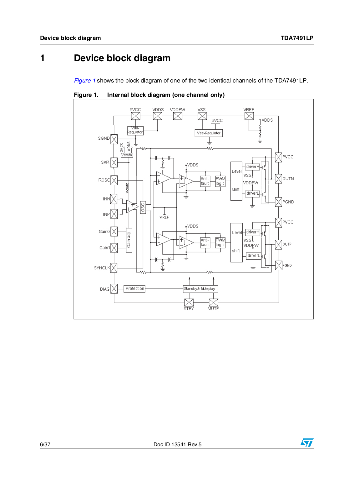
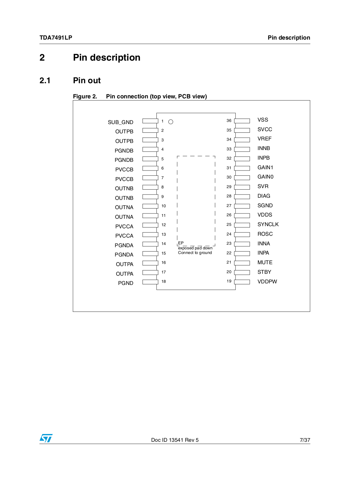
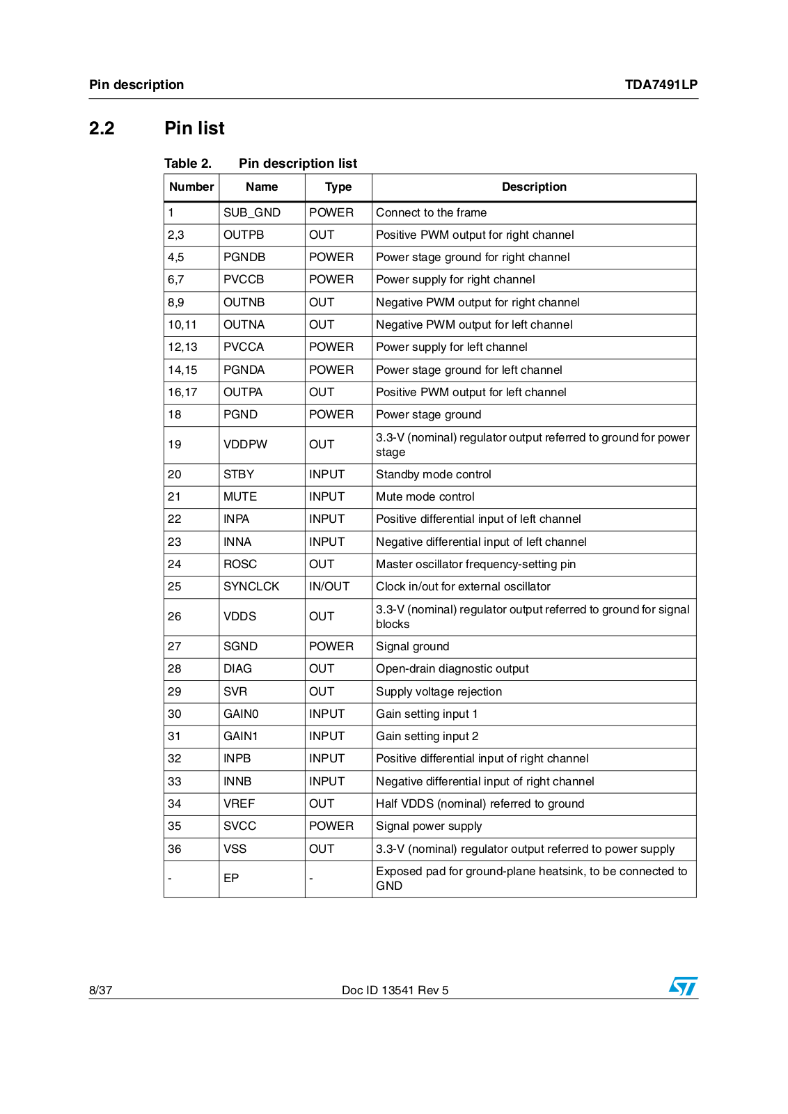
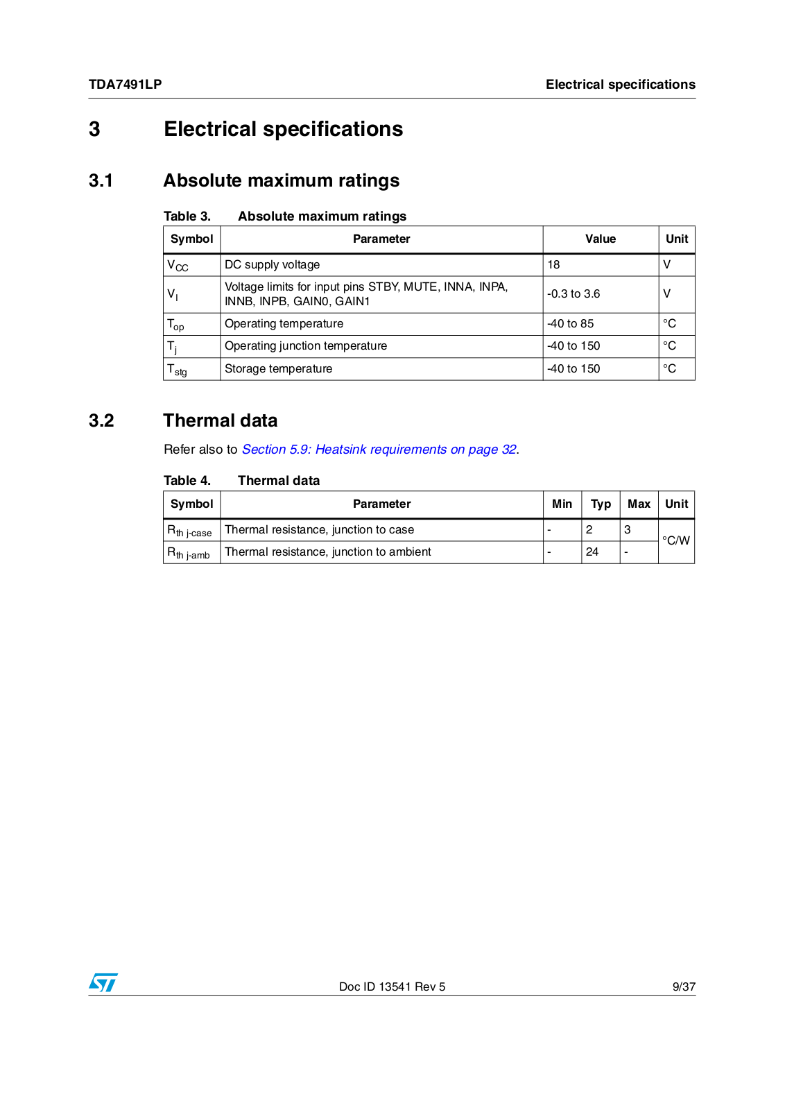
TDA7491LP
User Manual
37 pgs
1.15 Mb
0
Table of contents
Loading...
ST TDA7491LP User Manual
...
ST User Manual
Download
Specifications and Main Features
Frequently Asked Questions
User Manual
Download
Loading...
+
hidden pages
Unhide
You need points to download manuals.
1 point = 1 manual.
You can buy points or you can get point for every manual you upload.
Buy points
Upload your manuals
 Loading...