

Page 1

UM2464
User manual
SPC572L-DISP Discovery+ Board
Introduction
This manual provides information for the final user application developer on how to
configure and to use the SPC572L-DISP microcontroller evaluation board.
The discovery board SPC572L-DISP is based on the microcontroller SPC572L64E3, a high
performance 32-bit Power Architecture technology CPU, 1568KB flash in an eTQFP100
package.
The several interfaces including GPIO's, peripherals such as DSPI, LIN, UART, ISO CANFD make the SPC572L-DISP an excellent starter kit for the customer to quickly evaluate the
microcontroller as well as to develop and debug application. An integrated programmer
debugger allows debugging and programming the microcontroller without further tools. The
same circuit allows enabling a USB to serial communication channel (USB Virtual COM
port).
A standard JTAG port allows programming the microcontroller by using different
debug/programmer tools.
December 2018 UM2464 Rev 1 1/11
www.st.com
1
Page 2

Contents UM2464
Contents
1 SPC572L-DISP discovery board . . . . . . . . . . . . . . . . . . . . . . . . . . . . . . . 5
1.1 Debug interface . . . . . . . . . . . . . . . . . . . . . . . . . . . . . . . . . . . . . . . . . . . . . 5
1.2 I/O interface and connectors . . . . . . . . . . . . . . . . . . . . . . . . . . . . . . . . . . . 5
2 Hardware description . . . . . . . . . . . . . . . . . . . . . . . . . . . . . . . . . . . . . . . . 6
2.1 Power supply section . . . . . . . . . . . . . . . . . . . . . . . . . . . . . . . . . . . . . . . . . 6
2.1.1 External Power Supply . . . . . . . . . . . . . . . . . . . . . . . . . . . . . . . . . . . . . . 6
2.1.2 USB connection: 3.3 V . . . . . . . . . . . . . . . . . . . . . . . . . . . . . . . . . . . . . . . 6
2.2 Crystal oscillator . . . . . . . . . . . . . . . . . . . . . . . . . . . . . . . . . . . . . . . . . . . . . 7
2.3 Reset section . . . . . . . . . . . . . . . . . . . . . . . . . . . . . . . . . . . . . . . . . . . . . . . 7
2.4 User LEDs . . . . . . . . . . . . . . . . . . . . . . . . . . . . . . . . . . . . . . . . . . . . . . . . . 7
2.5 Integrated USB programmer/debugger and JTAG port . . . . . . . . . . . . . . . 7
2.6 CAN . . . . . . . . . . . . . . . . . . . . . . . . . . . . . . . . . . . . . . . . . . . . . . . . . . . . . . 8
2.7 FlexRay . . . . . . . . . . . . . . . . . . . . . . . . . . . . . . . . . . . . . . . . . . . . . . . . . . . 8
2.8 LIN and UART . . . . . . . . . . . . . . . . . . . . . . . . . . . . . . . . . . . . . . . . . . . . . . 8
2.9 4x2x25 connector adapter . . . . . . . . . . . . . . . . . . . . . . . . . . . . . . . . . . . . . 8
Appendix . . . . . . . . . . . . . . . . . . . . . . . . . . . . . . . . . . . . . . . . . . . . . . . . . . . . . . . . . . . 9
Revision history . . . . . . . . . . . . . . . . . . . . . . . . . . . . . . . . . . . . . . . . . . . . . . . . . . . . 10
2/11 UM2464 Rev 1
Page 3

UM2464 List of tables
List of tables
Table 1. PSU section-LEDs description . . . . . . . . . . . . . . . . . . . . . . . . . . . . . . . . . . . . . . . . . . . . . . . 6
Table 2. PSU Section-test points . . . . . . . . . . . . . . . . . . . . . . . . . . . . . . . . . . . . . . . . . . . . . . . . . . . . 7
Table 3. User LEDs . . . . . . . . . . . . . . . . . . . . . . . . . . . . . . . . . . . . . . . . . . . . . . . . . . . . . . . . . . . . . . 7
Table 4. Document revision history . . . . . . . . . . . . . . . . . . . . . . . . . . . . . . . . . . . . . . . . . . . . . . . . . 10
UM2464 Rev 1 3/11
3
Page 4

List of figures UM2464
List of figures
Figure 1. SPC572L-DISP board. . . . . . . . . . . . . . . . . . . . . . . . . . . . . . . . . . . . . . . . . . . . . . . . . . . . . . 5
Figure 2. PSU section - DC input . . . . . . . . . . . . . . . . . . . . . . . . . . . . . . . . . . . . . . . . . . . . . . . . . . . . 6
4/11 UM2464 Rev 1
Page 5

UM2464 SPC572L-DISP discovery board
1 SPC572L-DISP discovery board
Figure 1. SPC572L-DISP board
The SPC572L-DISP evaluation kit consists of:
SPC572L-DISP Discovery board (see Figure 1).
USB type A to mini-B cable.
12 V DC power Supply (EU Plug).
All GPIOs and the main signals are accessible by a 4x37 0.1” pin array.
Free ready-to-run application firmware examples are available inside SPC5Studio
(www.st.com/spc5studio) to support quick evaluation and development.
The PCB, the components and all the HW parts assembled in this board meet the
requirements of the applicable RoHS directives.
1.1 Debug interface
14-pin JTAG interface.
USB integrated programmer debugger.
1.2 I/O interface and connectors
PSU plug (+12V).
CAN and LINFlex (Header 2x4 pin).
K-Line and UART (Header 2x4 pin).
UM2464 Rev 1 5/11
9
Page 6
Hardware description UM2464
2 Hardware description
2.1 Power supply section
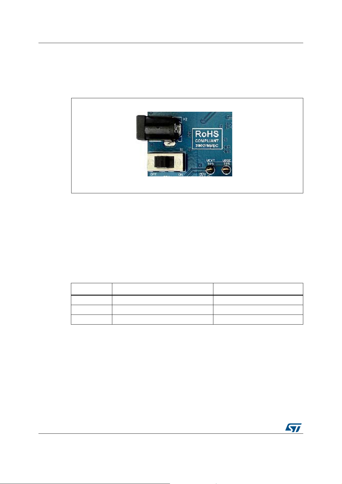
Figure 2. PSU section - DC input
2.1.1 External Power Supply
The external DC supply must be plugged in X2; the switch S1 allows the user to disconnect
the external supply source.
The voltage regulators, U15 and U16 are used to generate 5 V and +3.3V respectively. U14
is a pre-regulator and it must be used when the DC voltage supply is higher than 12 V (i.e.
when the board is used in an application with a DC input higher than 12 V).
The LEDs D7, D9 and D10 are all ON when the board power supply section works properly
and the switch S1 is set to ON position.
Item Color Function
D7 Green Vext(+12V)
D9 Green 5V
D10 Green 3.3 V
Table 1. PSU section-LEDs description
2.1.2 USB connection: 3.3 V
If the integrated programmer/debugger is used, 5V from the USB port supplies the board.
U17 and U18 are used to implement an automatic switch.
The VDD_HV_Flex, VDD_HV_JTAG and VDDHV_ADR voltage level is set with the jumper
JP2, JP3 and JP4.
Some test pins are present to monitor the supply voltage levels.
6/11 UM2464 Rev 1
Page 7

UM2464 Hardware description
Test point name Signal/Voltage
TP2 3.3V_USB
TP3 V_Ext (+12V)
TP4 GND
TP5 VPRE
TP6 +5V
TP7 3.3 V
2.2 Crystal oscillator
The external oscillator is connected to a 20MHz crystal (Y2).
2.3 Reset section
U19 drives the reset signal to low level till the VDD_HV_IO level is lower than a fixed level
and it provides a reset pulse when the pushbutton S2 is pressed.
JP21 and JP22 connect the reset signal to the ESR0 and PQRST signal respectively
(default connection: JP21 is closed).
Table 2. PSU Section-test points
2.4 User LEDs
Three LEDs (D15, D16 and D17) are available for user purposes. The jumpers JP18, JP23
and JP24 allow disconnecting the cathode of each LED's and PE[0], PE[1] and PE[2] can be
used for a different purpose.
LED Color µC Pin - Function
D15 Green PE0
D16 Green PE1
D17 Green PE2
Table 3. User LEDs
2.5 Integrated USB programmer/debugger and JTAG port
The integrated debugger allows the user to program and to debug the software applications.
The integrated tool is based on the UDE PLS software and the device FTDI2232H.
The SPC572L-DISP discovery board includes a full-featured, perpetual code-limited PLS
software license. The debugger serial number is reported on a label applied on the board.
The integrated debugger SW is accessible via SPC5Studio (www.st.com/spc5studio), a
ST's free integrated development environment. To download the debugger software and to
activate the license refer to the PLS website.
UM2464 Rev 1 7/11
9
Page 8

Hardware description UM2464
Some jumpers enable the JTAG port. The board with this setup can be programmed by
using an external programmer. By removing RP1, the integrated programmer is
disconnected and the JTAG port will be enabled to program the microcontroller.
Note: If the USB cable is not used and the board is supplied by using an external DC source, it is
suggested to test the external JTAG programmer before removing the resistor array RP1.
2.6 CAN
U24 is the CAN communication transceiver. Different devices can be assembled:
AMIS30663 or MCP2561 and JP14 must be configured properly considering the transceiver
assembled.
The jumper JP15 connects the termination resistor for CAN bus (120 Ω) while TP14 and
TP15 allow monitoring the output signals CANL and CANH respectively.
The CAN Rx and Tx signals are connected to P4.
2.7 FlexRay
The U23 is the transceiver to manage the FlexRay communication; JP10, JP11 and JP12
allow selection between two channels (FlexRay_0_CA and FlexRay_0_CB). The outputs
are connected to P4, pin 3 and 5; TP12 and TP13 allow monitoring the FlexRay output
signals.
2.8 LIN and UART
The LINFlex supports LIN Master mode, LIN Slave mode and UART mode. JP5 and JP6 are
dedicated to select among LIN_0, LIN_1 and K.
U21 is the transceiver to support the LIN communication, whereas U22 is used to support KLine.
The output of these two communication channels is connected to the connector P3.
2.9 4x2x25 connector adapter
This is a female pin array used to connect the main board to a small PCB with the
microcontroller.
8/11 UM2464 Rev 1
Page 9

UM2464 Appendix
Appendix
The following precautions are recommended when using the SPC572L-DISP:
1. Do not modify or manipulate the board when it is supplied by using the external DC
source or the USB cable.
2. Do not supply the board with AC source.
3. The connectors and cables should be plugged and removed when the board is not
supplied.
4. Please use antistatic tools.
UM2464 Rev 1 9/11
9
Page 10

Revision history UM2464
Revision history
Date Revision Changes
19-Dec-2018 1 Initial release.
Table 4. Document revision history
10/11 UM2464 Rev 1
Page 11

UM2464
IMPORTANT NOTICE – PLEASE READ CAREFULLY
STMicroelectronics NV and its subsidiaries (“ST”) reserve the right to make changes, corrections, enhancements, modifications, and
improvements to ST products and/or to this document at any time without notice. Purchasers should obtain the latest relevant information on
ST products before placing orders. ST products are sold pursuant to ST’s terms and conditions of sale in place at the time of order
acknowledgement.
Purchasers are solely responsible for the choice, selection, and use of ST products and ST assumes no liability for application assistance or
the design of Purchasers’ products.
No license, express or implied, to any intellectual property right is granted by ST herein.
Resale of ST products with provisions different from the information set forth herein shall void any warranty granted by ST for such product.
ST and the ST logo are trademarks of ST. All other product or service names are the property of their respective owners.
Information in this document supersedes and replaces information previously supplied in any prior versions of this document.
© 2018 STMicroelectronics – All rights reserved
UM2464 Rev 1 11/11
11
 Loading...