

ST SPBT2532C2.AT2 User Manual
SPBT2532C2.AT2
Bluetooth® V2.1 + EDR module class 2 embedding SPP and AT
commands
Datasheet − production data
Features
profiles
®
radio
■ Bluetooth
– Fully embedded Bluetooth v2.1 + EDR with
– Class 2 module
– Complete RF ready module
■ ST micro Cortex-M3 microprocessor up to
72 MHz
■ Memory
– 256 kb Flash memory
– 48 kb RAM memory
■ Data rate
– 1.5 Mbps maximum data rate
■ Serial interface
– UART up to 2.0 Mbps
■ General I/O
– 4 general purpose I/Os
■ User interface
– AT2 command set (abSerial)
– Firmware upgrade over UART
■ CE and Bluetooth qualified
■ EPL (end product listing) fulfilled
■ Single voltage supply: 3.3 V typical
■ Micro-sized form factor: 10.5 x 13.5 x 2.5 mm
■ Operating temperature range: -40 °C to 85 °C
July 2012 Doc ID 023461 Rev 1 1/27
This is information on a product in full production.
www.st.com
27

Contents SPBT2532C2.AT2
Contents
1 Description . . . . . . . . . . . . . . . . . . . . . . . . . . . . . . . . . . . . . . . . . . . . . . . . . 6
2 RoHS compliance . . . . . . . . . . . . . . . . . . . . . . . . . . . . . . . . . . . . . . . . . . . 7
3 Applications . . . . . . . . . . . . . . . . . . . . . . . . . . . . . . . . . . . . . . . . . . . . . . . . 7
4 Software architecture . . . . . . . . . . . . . . . . . . . . . . . . . . . . . . . . . . . . . . . . 8
4.1 Lower layer stack . . . . . . . . . . . . . . . . . . . . . . . . . . . . . . . . . . . . . . . . . . . . 8
4.2 Upper layer stack: Amp'ed UP . . . . . . . . . . . . . . . . . . . . . . . . . . . . . . . . . . 8
4.3 AT command set: abSerial . . . . . . . . . . . . . . . . . . . . . . . . . . . . . . . . . . . . . 8
4.4 Bluetooth firmware implementation . . . . . . . . . . . . . . . . . . . . . . . . . . . . . . 9
5 Hardware specifications . . . . . . . . . . . . . . . . . . . . . . . . . . . . . . . . . . . . . 10
5.1 Recommended operating conditions . . . . . . . . . . . . . . . . . . . . . . . . . . . . 10
5.2 Absolute maximum ratings . . . . . . . . . . . . . . . . . . . . . . . . . . . . . . . . . . . . 10
5.3 High speed CPU mode current consumption . . . . . . . . . . . . . . . . . . . . . . 11
5.4 Standard CPU mode current consumption . . . . . . . . . . . . . . . . . . . . . . . . 11
5.5 I/O operating characteristics . . . . . . . . . . . . . . . . . . . . . . . . . . . . . . . . . . . 12
5.6 Selected RF characteristics . . . . . . . . . . . . . . . . . . . . . . . . . . . . . . . . . . . 12
5.7 Pin assignment . . . . . . . . . . . . . . . . . . . . . . . . . . . . . . . . . . . . . . . . . . . . . 13
5.8 Pin placement . . . . . . . . . . . . . . . . . . . . . . . . . . . . . . . . . . . . . . . . . . . . . . 14
5.9 Layout drawing . . . . . . . . . . . . . . . . . . . . . . . . . . . . . . . . . . . . . . . . . . . . . 15
6 Hardware block diagram . . . . . . . . . . . . . . . . . . . . . . . . . . . . . . . . . . . . . 16
7 Hardware design . . . . . . . . . . . . . . . . . . . . . . . . . . . . . . . . . . . . . . . . . . . 17
7.1 Module reflow installation . . . . . . . . . . . . . . . . . . . . . . . . . . . . . . . . . . . . . 17
7.2 GPIO interface . . . . . . . . . . . . . . . . . . . . . . . . . . . . . . . . . . . . . . . . . . . . . 18
7.3 UART interface . . . . . . . . . . . . . . . . . . . . . . . . . . . . . . . . . . . . . . . . . . . . . 18
8 Application information . . . . . . . . . . . . . . . . . . . . . . . . . . . . . . . . . . . . . 20
8.1 Antenna choice . . . . . . . . . . . . . . . . . . . . . . . . . . . . . . . . . . . . . . . . . . . . 20
8.2 Antenna coupling . . . . . . . . . . . . . . . . . . . . . . . . . . . . . . . . . . . . . . . . . . . 22
2/27 Doc ID 023461 Rev 1

SPBT2532C2.AT2 Contents
8.3 Example of trace calculation . . . . . . . . . . . . . . . . . . . . . . . . . . . . . . . . . . 22
8.4 Reset circuit . . . . . . . . . . . . . . . . . . . . . . . . . . . . . . . . . . . . . . . . . . . . . . . 23
8.4.1 External reset circuit . . . . . . . . . . . . . . . . . . . . . . . . . . . . . . . . . . . . . . . 23
8.4.2 Internal reset circuit . . . . . . . . . . . . . . . . . . . . . . . . . . . . . . . . . . . . . . . . 23
9 Regulatory compliance . . . . . . . . . . . . . . . . . . . . . . . . . . . . . . . . . . . . . . 24
10 Ordering information . . . . . . . . . . . . . . . . . . . . . . . . . . . . . . . . . . . . . . . 25
11 Revision history . . . . . . . . . . . . . . . . . . . . . . . . . . . . . . . . . . . . . . . . . . . 26
Doc ID 023461 Rev 1 3/27

List of tables SPBT2532C2.AT2
List of tables
Table 1. Recommended operating conditions . . . . . . . . . . . . . . . . . . . . . . . . . . . . . . . . . . . . . . . . . 10
Table 2. Absolute maximum ratings . . . . . . . . . . . . . . . . . . . . . . . . . . . . . . . . . . . . . . . . . . . . . . . . . 10
Table 3. High speed CPU mode current consumption . . . . . . . . . . . . . . . . . . . . . . . . . . . . . . . . . . . 11
Table 4. Standard CPU mode current consumption . . . . . . . . . . . . . . . . . . . . . . . . . . . . . . . . . . . . . 11
Table 5. I/O operating characteristics . . . . . . . . . . . . . . . . . . . . . . . . . . . . . . . . . . . . . . . . . . . . . . . . 12
Table 6. Selected RF characteristics . . . . . . . . . . . . . . . . . . . . . . . . . . . . . . . . . . . . . . . . . . . . . . . . 12
Table 7. Pin assignment . . . . . . . . . . . . . . . . . . . . . . . . . . . . . . . . . . . . . . . . . . . . . . . . . . . . . . . . . . 13
Table 8. Soldering. . . . . . . . . . . . . . . . . . . . . . . . . . . . . . . . . . . . . . . . . . . . . . . . . . . . . . . . . . . . . . . 17
Table 9. Ordering information . . . . . . . . . . . . . . . . . . . . . . . . . . . . . . . . . . . . . . . . . . . . . . . . . . . . . . 25
Table 10. Document revision history . . . . . . . . . . . . . . . . . . . . . . . . . . . . . . . . . . . . . . . . . . . . . . . . . 26
4/27 Doc ID 023461 Rev 1

SPBT2532C2.AT2 List of figures
List of figures
Figure 1. FW architecture . . . . . . . . . . . . . . . . . . . . . . . . . . . . . . . . . . . . . . . . . . . . . . . . . . . . . . . . . . 9
Figure 2. Pin placement . . . . . . . . . . . . . . . . . . . . . . . . . . . . . . . . . . . . . . . . . . . . . . . . . . . . . . . . . . . 14
Figure 3. Ground plane diagram . . . . . . . . . . . . . . . . . . . . . . . . . . . . . . . . . . . . . . . . . . . . . . . . . . . . 14
Figure 4. Layout drawing . . . . . . . . . . . . . . . . . . . . . . . . . . . . . . . . . . . . . . . . . . . . . . . . . . . . . . . . . . 15
Figure 5. SPBT2532C2.AT2 module block diagram . . . . . . . . . . . . . . . . . . . . . . . . . . . . . . . . . . . . . 16
Figure 6. Soldering profile . . . . . . . . . . . . . . . . . . . . . . . . . . . . . . . . . . . . . . . . . . . . . . . . . . . . . . . . . 18
Figure 7. Connection to host device . . . . . . . . . . . . . . . . . . . . . . . . . . . . . . . . . . . . . . . . . . . . . . . . . 18
Figure 8. Typical RS232 circuit . . . . . . . . . . . . . . . . . . . . . . . . . . . . . . . . . . . . . . . . . . . . . . . . . . . . . 19
Figure 9. Example of antenna integration on the STEVAL-SPBT2ATV3. . . . . . . . . . . . . . . . . . . . . . 20
Figure 10. Antenna printed on PCB . . . . . . . . . . . . . . . . . . . . . . . . . . . . . . . . . . . . . . . . . . . . . . . . . . . 21
Figure 11. SMD antenna . . . . . . . . . . . . . . . . . . . . . . . . . . . . . . . . . . . . . . . . . . . . . . . . . . . . . . . . . . . 21
Figure 12. SMA connector for external antenna . . . . . . . . . . . . . . . . . . . . . . . . . . . . . . . . . . . . . . . . . 21
Figure 13. Parameters for trace matching . . . . . . . . . . . . . . . . . . . . . . . . . . . . . . . . . . . . . . . . . . . . . . 22
Figure 14. External reset circuit . . . . . . . . . . . . . . . . . . . . . . . . . . . . . . . . . . . . . . . . . . . . . . . . . . . . . . 23
Figure 15. Internal reset circuit . . . . . . . . . . . . . . . . . . . . . . . . . . . . . . . . . . . . . . . . . . . . . . . . . . . . . . 23
Doc ID 023461 Rev 1 5/27

Description SPBT2532C2.AT2
1 Description
The SPBT2532C2.AT2 is an easy to use Bluetooth module, compliant with Bluetooth v2.1 +
EDR.
The module is the smallest form factor available which provides a complete RF platform.
The SPBT2532C2.AT2 enables electronic devices with wireless connectivity, not requiring
any RF experience or expertise for integration into the final product. The SPBT2532C2.AT2
module, being a certified solution, optimizes the time to market of the final application.
The module is designed for maximum performance in the minimum possible size including
fast speed UART and 4 general purpose I/O lines, several serial interface options, and up to
1.5 Mbps data throughput.
The SPBT2532C2.AT2 is a surface mount PCB module that provides fully embedded,
ready-to-use Bluetooth wireless technology. The reprogrammable Flash memory contains
embedded firmware for serial cable replacement using the Bluetooth SPP profile.
Embedded Bluetooth AT2 command firmware is a friendly interface, which realizes a simple
control for cable replacement, enabling communication with most Bluetooth enabled
devices, provided that the devices support the SPP profile. The SPBT2532C2.AT2,
supporting iAP profile, provides communication with Android
iOS Bluetooth enabled devices.
™
, smartphones, and Apple®
An Apple authentication IC is required to exchange data with an Apple device or access an
Apple device application. The AT2 FW includes the Bluetooth SPP profile capable of
recognizing the Apple authentication chip.
Customers using the Apple authentication IC must register as developers to become an
Apple certified MFI member. License fees may apply, for additional information visit:
http://developer.apple.com/programs/which-program/index.html.
Certified MFI developers developing electronic accessories that connect to the iPod
iPhone
®
, and iPad® gain access to technical documentation, hardware components,
®
,
technical support and certification logos.
Customized firmware for peripheral device interaction, power optimization, security, and
other proprietary features may be supported and can be ordered pre-loaded and configured.
6/27 Doc ID 023461 Rev 1

SPBT2532C2.AT2 RoHS compliance
2 RoHS compliance
ST modules are RoHS compliant and comply with ECOPACK® norms.
3 Applications
■ Serial cable replacement
■ M2M industrial control
■ Service diagnostic
■ Data acquisition equipment
■ Machine control
■ Sensor monitoring
■ Security system
■ Mobile health.
Doc ID 023461 Rev 1 7/27

Software architecture SPBT2532C2.AT2
4 Software architecture
4.1 Lower layer stack
● Bluetooth v2.1 + EDR
● Device power modes: active, sleep and deep sleep
● Wake-on Bluetooth feature optimized power consumption of host CPU
● Authentication and encryption
● Encryption key length from 8 bits to 128 bits
● Persistent Flash memory for BD address and user parameter storage
● All ACL (asynchronous connection less) packet types
● Point-to-point supported
● Master/slave switch supported during connection and post connection
● Dedicated inquiry access code for improved inquiry scan performance
● Dynamic packet selection channel quality driven data rate to optimize link performance
● Dynamic power control
● 802.11b co-existence AFH.
4.2 Upper layer stack: Amp'ed UP
● SPP, IAP, SDAP and GAP protocols
● RFComm, SDP, and L2CAP supported
● Multipoint with simultaneous slaves.
4.3 AT command set: abSerial
The complete command list including the iAP commands is reported in the UM1547 user
manual.
8/27 Doc ID 023461 Rev 1
SPBT2532C2.AT2 Software architecture
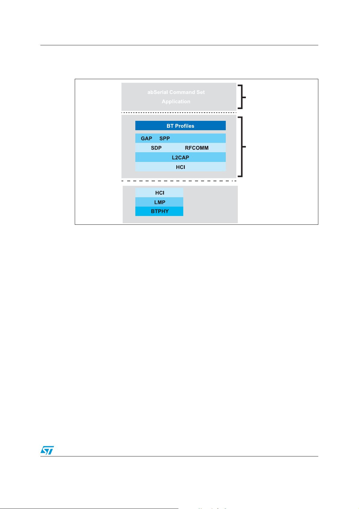
4.4 Bluetooth firmware implementation
Figure 1. FW architecture
abSerial AT Command Set
and/or custom application
Application
layer API
HCI over UART
iAP
Upper layer stack + BT
profiles:Amp’edUP
Lower layer BT stack
Bluetooth controller
AM14808v1
Doc ID 023461 Rev 1 9/27
 Loading...