

ST LM4041AICT-1.2, LM4041BICT-1.2, LM4041CICT-1.2, LM4041DICT-1.2, LM4041AILT-1.2 User Manual
...
Precision micropower shunt voltage reference
Features
■ Fixed 1.225 V typical output voltage
■ Ultra low operating current: 40 µA at 25 °C
■ High precision: +/- 0.1% @ 25 °C (0.2%, 0.5%
and 1% versions are also available)
■ Stable when used with capacitive loads
■ Industrial (- 40 to+ 85 °C) and Extended (- 40
to +125 °C) temperature range versions
available
■ 100 ppm/°C maximum temperature coefficient
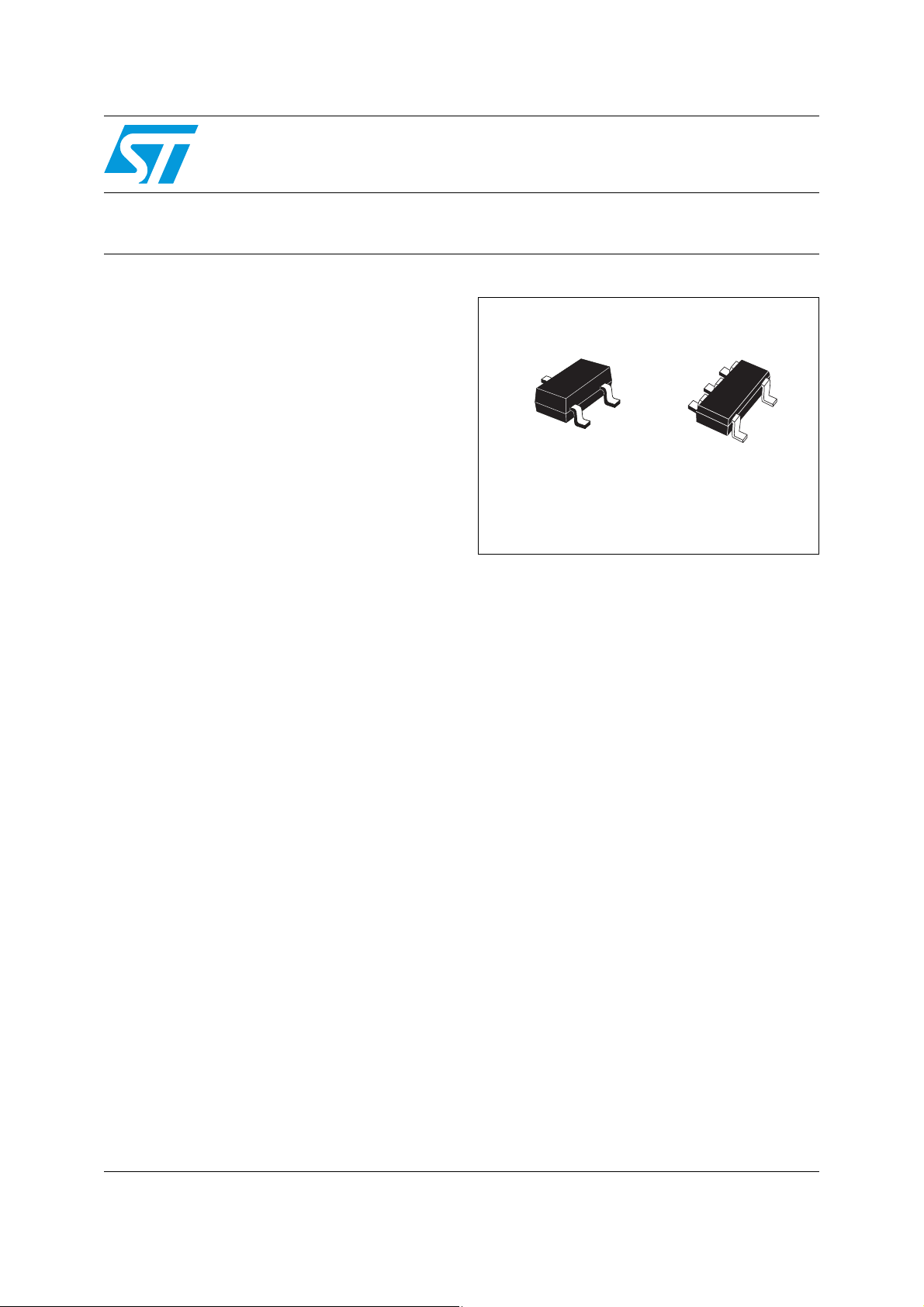
■ Available in SOT23-3L and SOT323-5L
packages
LM4041xx
Datasheet − production data
SOT23-3L
SOT323-5L
Applications
■ Computers
■ Battery chargers
■ Switch mode power supply
■ Battery operated equipment
■ Data acquisition systems
■ Energy management
■ Instrumentation
Description
The LM4041 is a micropower shunt voltage
reference, providing a stable 1.225 V output
voltage, with an initial accuracy of 0.1% @ 25 °C
and a low temperature coefficient. Available in
SOT323-5L and SOT23-3L surface mount
packages, it can be designed in applications
where space saving is a critical issue. The low
operating current is a key advantage for power
restricted designs. In addition, the LM4041 is very
stable and can be used in a broad range of
application conditions.
July 2012 Doc ID 018817 Rev 3 1/16
This is information on a product in full production.
www.st.com
16

Contents LM4041xx
Contents
1 Pin configuration . . . . . . . . . . . . . . . . . . . . . . . . . . . . . . . . . . . . . . . . . . . . 3
2 Maximum ratings . . . . . . . . . . . . . . . . . . . . . . . . . . . . . . . . . . . . . . . . . . . . 4
3 Electrical characteristics . . . . . . . . . . . . . . . . . . . . . . . . . . . . . . . . . . . . . 5
4 Typical performance characteristics . . . . . . . . . . . . . . . . . . . . . . . . . . . . 6
5 Package mechanical data . . . . . . . . . . . . . . . . . . . . . . . . . . . . . . . . . . . . . 8
6 Order codes . . . . . . . . . . . . . . . . . . . . . . . . . . . . . . . . . . . . . . . . . . . . . . . 14
7 Revision history . . . . . . . . . . . . . . . . . . . . . . . . . . . . . . . . . . . . . . . . . . . 15
2/16 Doc ID 018817 Rev 3
LM4041xx Pin configuration
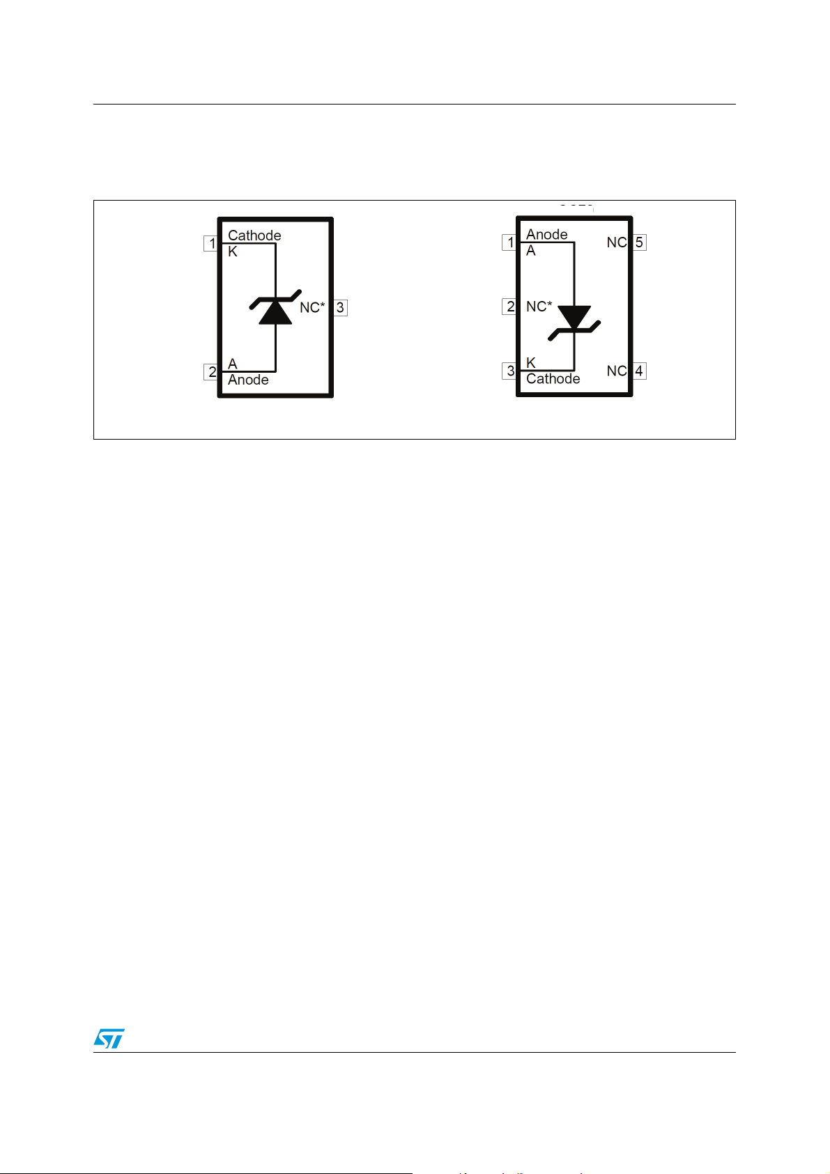
1 Pin configuration
Figure 1. Pin connection (top view)
AM09377v1
SOT23-3L SOT323-5L
* This pin must be left floating or connected to Anode pin.
AM09
378v1
Doc ID 018817 Rev 3 3/16
Maximum ratings LM4041xx
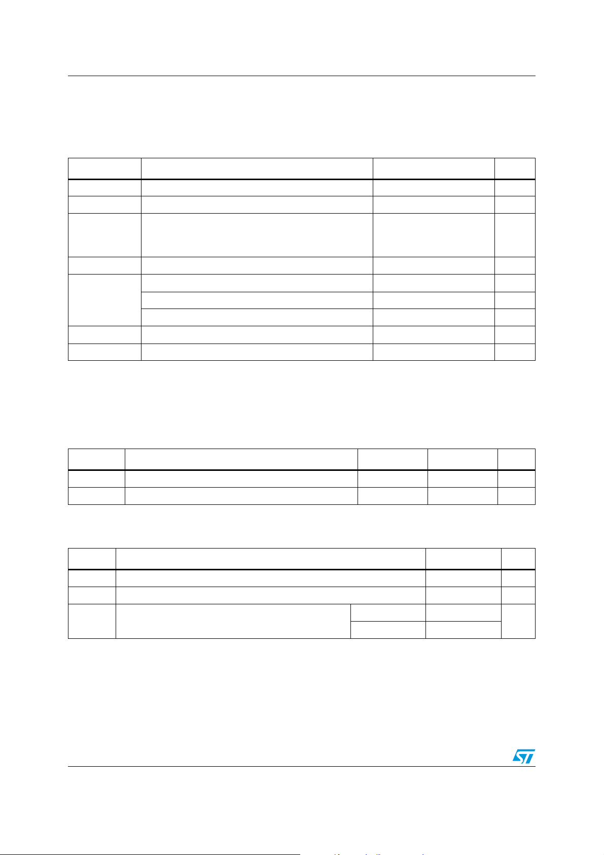
2 Maximum ratings
Table 1. Absolute maximum ratings
Symbol Parameter Value Unit
Reverse breakdown current 20 mA
Forward current 10 mA
Power dissipation
SOT23-3L
SOT323-5L
(1)
500
536
mW
Storage temperature - 65 to +150 °C
T
I
K
I
F
P
STG
D
Human Body Model (HBM) 2 kV
ESD
Machine Model (MM) 200 V
Charged Device Model 1500 V
T
LEAD
T
J
1. PD has been calculated with T
Lead temperature (soldering) 10 sec 260 °C
Max junction temperature +150 °C
= 25°C and T
AMB
JMAX
= 150 °C.
Note: Absolute maximum ratings are those values beyond which damage to the device may occur.
Functional operation under these conditions is not implied.
Table 2. Thermal data
Symbol Parameter SOT323-5L SOT23-3L Unit
R
R
thJA
thJC
Thermal resistance junction-ambient 233 248 °C/W
Thermal resistance junction-case 90 136 °C/W
Table 3. Operating conditions
Symbol Parameter Value Unit
I
KMIN
I
KMAX
T
OPER
4/16 Doc ID 018817 Rev 3
Minimum operating current 40 µA
Maximum operating current 12 mA
Industrial - 40 to + 85
Operating free air temperature range
Extended - 40 to + 125
°C
LM4041xx Electrical characteristics
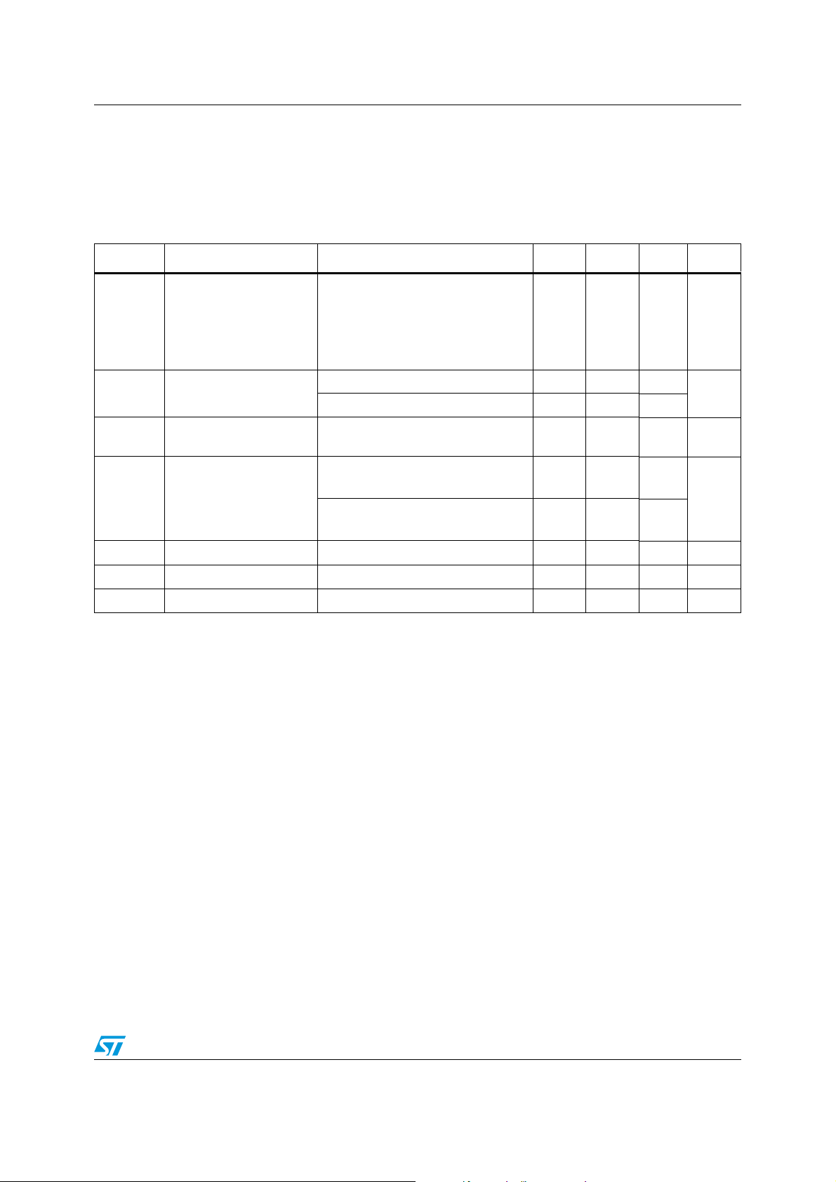
3 Electrical characteristics
T
= 25 °C, unless otherwise specified.
AMB
Table 4. Electrical characteristics
Symbol Parameter Test conditions Min. Typ. Max. Unit
= 100 µA
I
k
ΔV
Vk
I
kmin
/ΔT
k
Reverse breakdown
voltage
Minimum operating
current
Average temperature
coefficient
(2)
LM4041A, 0.1%
LM4041B, 0.2%
LM4041C, 0.5%
LM4041D, 1%
= 25 °C 25 40
T
amb
max
(1)
-40 °C < T
I
= 100 µA ± 36 ± 100 ppm/°C
k
amb
< T
1.2238
1.2225
1.219
1.213
1.225
1.2262
1.2275
1.231
1.237
50
V
µA
< Ik < 1 mA
I
kmin
- 40 °C < T
1 mA < I
ΔV
Reverse breakdown
voltage change with
/ΔI
k
k
operating current range
- 40 °C < T
R
K
e
1. T
max
2. The average temperature coefficient is defined as: 10
Static impedance ΔI
ka
Long term stability I
vh
Wide band noise I
n
= 85 °C for LM4041xI (industrial version) and T
= 100 µA to 1 mA 0.4 1 Ω
k
= 100 µA, t = 1000 hrs 120 ppm
k
= 100 µA, 10 Hz < f < 10 kHz 60 µV
k
max
max
(1)
(1)
k@25°C
x (T
max-Tmin
< T
amb
< 12 mA
k
< T
amb
= 125 °C for LM4041xE (extended version).
max
6
x {max(ΔVk) / [V
0.4
4
)]} [ppm/°C].
1
1.5
mV
8
10
RMS
Note: Limits are 100% production tested at 25 °C. Limits over temperature are guaranteed through
correlation and by design.
Doc ID 018817 Rev 3 5/16
 Loading...