

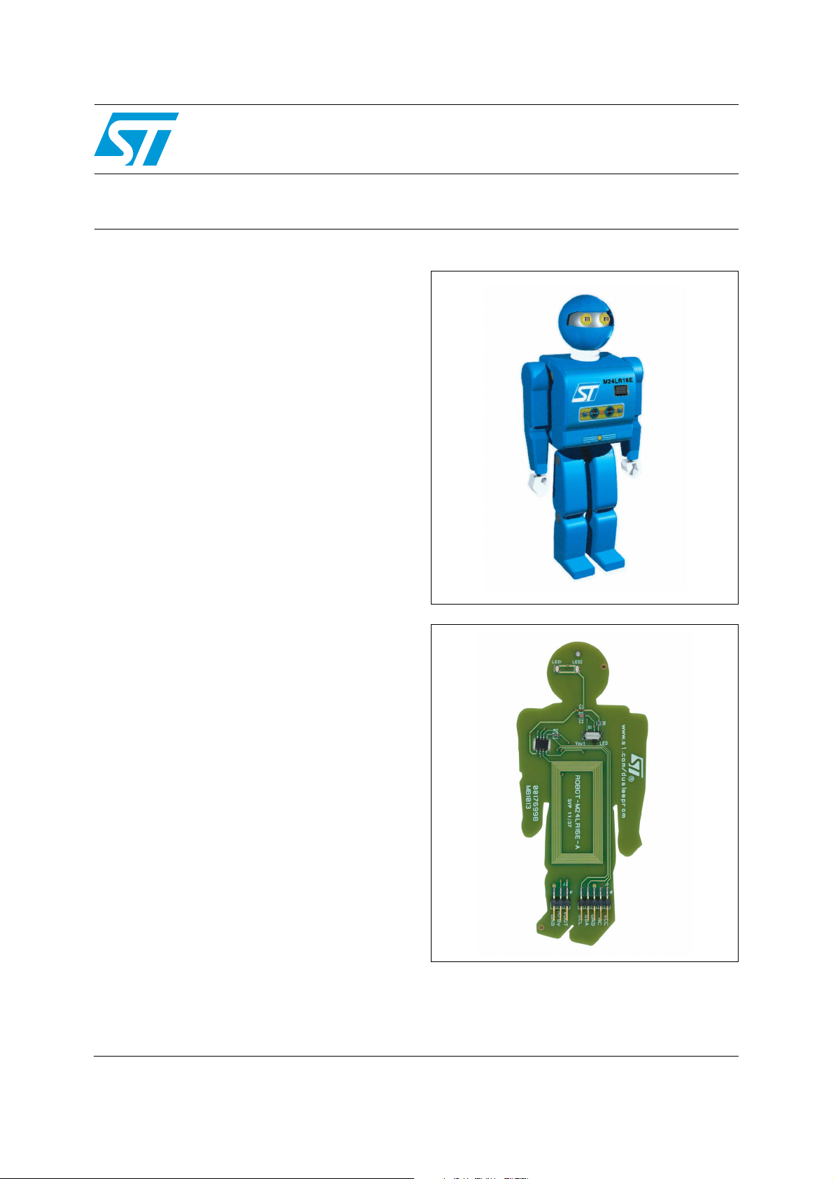
ROBOT-M24LR16E-A
Evaluation board for the M24LR16E-R dual interface EEPROM
Data brief
Features
■ 20 mm x 40 mm 13.56 MHz inductive antenna
etched on PCB
■ M24LR16E-R dual interface EEPROM
■ I²C connector
■ Energy harvesting output (V
OUT
) with a
capacitance filtering circuit
■ RF WIP/BUSY output with 20 kΩ pull-up
resistor, to indicate that an RF operation is
ongoing
Description
The ROBOT-M24LR16E-A is a ready-to-use PCB
that features an M24LR16-R dual interface
EEPROM IC connected to an I²C bus and a
20 mm x 40 mm 13.56 MHz etched RF antenna.
It also features two LEDs, powered by the
M24LR16E-R V
The ROBOT-M24LR16E-A has three functions:
Switch in the “LED” position: the robot
demonstrates energy harvesting by powering the
LED when a sufficient magnetic field is captured.
pin and an output connector.
OUT
Switch in the “V
” position: the energy
OUT
captured from the electromagnetic field is used to
power an external application through the V
OUT
pin.
RF WIP/BUSY function: for the RF WIP/BUSY
pin of M24LR16E-R, please refer to the
M24LR16E-R datasheet for further details.
To demonstrate the energy harvesting function,
the ROBOT-M24LR16E-A can be used in
conjunction with ST DEMO-CR95HF-A
demonstration board.
September 2011 Doc ID 022238 Rev 1 1/5
For further information contact your local STMicroelectronics sales office.
www.st.com
5
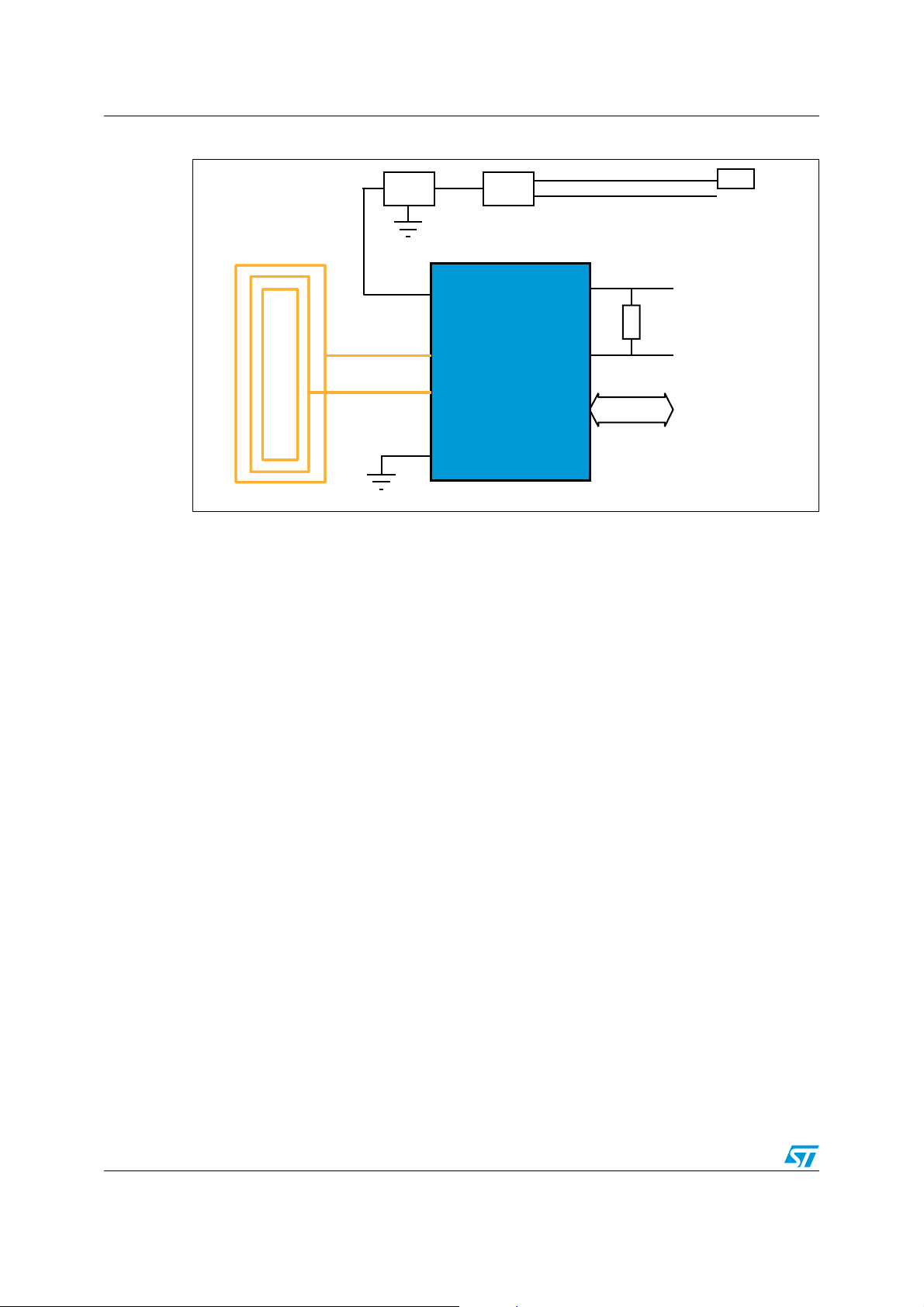
Figure 1. Functional block diagram
-36
-,2%!
2&7)0"539
6##
2&7)0"539
3#,
3$!
6/54
!#
!#
'.$
6##
)#BUS
K7
&ILTERING
CIRCUIT
3WITCH
6/54
,%$S
ROBOT-M24LR16E-A
2/5 Doc ID 022238 Rev 1
 Loading...