

Page 1

GENERAL INFORMATION
0000-00
GENERAL INFORMATION
GENERAL INFORMATION
1. HOW TO READ ELECTRICAL WIRING
DIAGRAM...............................................
3
Page 2

Page 3

0-3
GENERAL INFORMATION
REXTON 2007.09
0000-00
GENERAL INFORMATION
1. HOW TO READ ELECTRICAL WIRING DIAGRAM
Position Explanation
A
- Upper horizontal lines : Power supply lines
- Power supply lines : 30, 15, 15A, 15C, 58
B
- Ef20 or F2 : Fuse Number
·Ef20 : Fuse No #20 in engine room compartment
·F2 : Fuse No #2 in passenger room compartment
C
- Connector (C101 ~ C903)
·Connector No C203 terminal No1
·Refer to Major Connector Position (Section 2)
D
- S201 : Splice pack (S201 ~ S207)
·Refer to Major Splice Pack Position (Section2)
E
- Wiring Harness Color
·Refer to Wiring Harness Color Abbreviation
F
- Internal circuit of component (Relay)
(Component Name and Terminal Number)
G
- Internal circuit of component (Switch)
(Component Name, Terminal Number and Connecting Wiring Circuit)
H
- Lower horizontal line : Ground line
·Ground position (G101 ~ G402)
·B : Body Ground
·Refer to Major Ground Position (Section2)
1) HOW TO READ ELECTRICAL WIRING DIAGRAM
2) CONTENTS OF ELECTRICAL WIRING DIAGRAM (CIRCUIT)
Page 4

0-4
REXTON 2007.09
0000-00
GENERAL INFORMATION
3) CIRCUIT IDENTIFICATION SYMBOL
Identification Symbol Meaning
C Connector
D Diode
Ef Fuse in engine room fuse & relay box
F Fuse in passenger room fuse box
G Ground
S Splice pack (Junction connector)
5) WIRING HARNESS COLOR IDENTIFICATION
Abbreviation Color Abbreviation Color
Br Brown Sb Sky Blue
G Green R Red
V Violet L Blue
P Pink Y Yellow
W White Gr Gray
Or Orange B Black
Lg Light Green
6) HOW TO CHECK TERMINAL NUMBER OF CONNECTOR
Terminal number is given based on Female Terminal Male Connector
▶
ex) Terminal Number 4 of C901 connection-
Power supply No. Power supply condition
15 Battery Voltage (B+) supply in Ignition Switch “ON” and “ST” (IGN
1)
15A Battery Voltage (B+) supply in Ignition Switch “ON” (IGN 2)
15C Battery Voltage (B+) supply in Ignition Switch “ON” and “ACC”
30 Battery Voltage (B+) supply directly regardless of Ignition Switch
31 Ground connected to battery (-)
58
Battery Voltage (B+) supply in Head Lamp Switch 1st and 2nd step
(Illumination circuit)
4) FUNCTION OF POWER SUPPLY LINE (NUMBER)
Page 5

0-5
GENERAL INFORMATION
REXTON 2007.09
0000-00
7) PART LOCATION ACCORDING TO PART NUMBER
Ex.) C 1 0 2
▶
C : Symbol character for connector-
Symbol Character Description
C Connector (Connecting part that connects two wiring harness)
D Diode
G Ground
S Splice pack (Joint connector that connects various wiring harness)
1 : Part location number-
Part number according to locating section-
Part Numbe Location
□ 1□□ Engine compartment
□ 2□□ Instrument panel
□ 3□□ Passenger compartment
□ 4□□ Tailgate
□ 9□□ Underbody
In the locating section, the assignment for part number startsfrom left bottom and
proceeds clockwise.
In the fuse and relay box or the instrument panel, the partnumber is assigned from
left top to light bottom.
-
-
8) ELECTRIC SYMBOLS
Page 6

Page 7

CONNECTOR/GROUND
8201-00/8210-00/8210-02/8210-03/8210-09/8210-10/8210-06/8210-07/8210-08
CONNECTOR/GROUND
WIRING
8201-00 WIRING HARNESS,
COMPONENTS LOCATION.........
CONNECTOR/GROUND
8210-00 W/H ENGINE ROOM.....................
8210-02 W/H MAIN.....................................
8210-03 W/H FLOOR..................................
8210-09 W/H ROOF....................................
8210-06 W/H DRIVER DOOR......................
8210-07 W/H PASSENGER DOOR.............
8210-08 W/H RR DOOR..............................
8210-10 W/H TAIL GATE...........................
3
24
25
27
29
29
30
30
31
Page 8

Page 9

0-3
CONNECTOR/GROUND
REXTON 2007.09
8201-00
WIRING HARNESS
8201-00
WIRING HARNESS, COMPONENTS LOCATION
1) WIRING HARNESS
2) COMPONENTS LOCATION
Page 10

0-4
REXTON 2007.09
8201-00
CONNECTOR/GROUND
3) CONNECTOR, GROUND & SPLICE PACK INFORMATION
CONNECTOR
▶
Page 11

0-5
CONNECTOR/GROUND
REXTON 2007.09
8201-00
GROUND
▶
SPLICE PACK
▶
Page 12

0-6
REXTON 2007.09
8201-00
CONNECTOR/GROUND
4) SPLICE PACK CIRCUIT
S201 (GND)
▶
S202
▶
S203 (CAN)
▶
S204 (GND)
▶
S205
▶
S206 (ILL)
▶
Page 13

0-7
CONNECTOR/GROUND
REXTON 2007.09
8201-00
S207
▶
S301 (CAN)
▶
Page 14

0-8
REXTON 2007.09
8201-00
CONNECTOR/GROUND
5) CONNECTOR CIRCUIT
C103
▶
C105
▶
C106
▶
C101
▶
C102
▶
C104
▶
Page 15

0-9
CONNECTOR/GROUND
REXTON 2007.09
8201-00
C107
▶
C109
▶
C110
▶
C111
▶
C112
▶
C114
▶
C113
▶
C108
▶
Page 16

0-10
REXTON 2007.09
8201-00
CONNECTOR/GROUND
C115
▶
(D27DT)
C115
▶
(D27DTP)
Page 17

0-11
CONNECTOR/GROUND
REXTON 2007.09
8201-00
C115
▶
(GSL)
▶C204
▶C201
▶202
▶C203
Page 18

0-12
REXTON 2007.09
8201-00
CONNECTOR/GROUND
C205
▶
C206
▶
C207
▶
Page 19

0-13
CONNECTOR/GROUND
REXTON 2007.09
8201-00
C209
▶
C210
▶
▶C211
(Side A/Bag)
▶C212
▶C213
▶C213A
Page 20

0-14
REXTON 2007.09
8201-00
CONNECTOR/GROUND
C214
▶
C215
▶
C217
▶
(Side A/Bag)
C216
▶
Page 21

0-15
CONNECTOR/GROUND
REXTON 2007.09
8201-00
C218
▶
C220
▶
C219
▶
Page 22

0-16
REXTON 2007.09
8201-00
CONNECTOR/GROUND
C301
▶
C302
▶
C303
▶
(W/ Memory, Power)
(W/O Memory)
(W/ Memory, Power)
Page 23

0-17
CONNECTOR/GROUND
REXTON 2007.09
8201-00
▶C306
▶C352
▶C305
(W/ Memory, Power)
(W/O Memory)
(W/ Memory, Power)
▶C304 ▶C351
Page 24

0-18
REXTON 2007.09
8201-00
CONNECTOR/GROUND
▶C381
▶C371
▶C362
▶C361
Page 25

0-19
CONNECTOR/GROUND
REXTON 2007.09
8201-00
▶C394
▶C901
▶C902
▶C372
▶C382
▶C391
▶C392
▶C393
(A/T)
(M/T)
(GSL)
(DSL)
Page 26

0-20
REXTON 2007.09
8201-00
CONNECTOR/GROUND
▶C906
▶C907
▶C908
▶C903
▶C904
▶C905
Page 27

0-21
CONNECTOR/GROUND
REXTON 2007.09
8201-00
WIRNING CONNECTOR
▶
Page 28

0-22
REXTON 2007.09
8201-00
CONNECTOR/GROUND
▶UNIT CONNECTOR
▶SWITCH CONNECTOR
Page 29

0-23
CONNECTOR/GROUND
REXTON 2007.09
8201-00
▶MODE CONNECTOR
▶SENSOR CONNECTOR
▶LAMP CONNECTOR
▶ETC.
Page 30

0-24
REXTON 2007.09
8210-00
CONNECTOR/GROUND
CONNECTOR
8210-00
W/H ENGINE ROOM
Page 31

0-25
CONNECTOR/GROUND
REXTON 2007.09
8210-02
8210-02
W/H MAIN
Page 32

0-26
REXTON 2007.09
8210-02
CONNECTOR/GROUND
Page 33

0-27
CONNECTOR/GROUND
REXTON 2007.09
8210-03
8210-03
W/H FLOOR
Page 34

0-28
REXTON 2007.09
8210-03
CONNECTOR/GROUND
Page 35

0-29
CONNECTOR/GROUND
REXTON 2007.09
8210-09
8210-09
W/H ROOF
8210-06
W/H DRIVER DOOR
Page 36

0-30
REXTON 2007.09
8210-07
CONNECTOR/GROUND
8210-07
W/H PASSENGER DOOR
8210-08
W/H RR DOOR
Page 37

0-31
CONNECTOR/GROUND
REXTON 2007.09
8210-10
8210-10
W/H TAIL GATE
Page 38

Page 39

POWER DISTRIBUTION
8410-02/8410-04/8401-06
POWER DISTRIBUTION
FUSE/RELAY
8410-02 ENGINE ROOM FUSE &
RELAY BOX.................................
8410-04 I/P - FUSE BOX............................
8401-06 I/P - RELAY BOX..........................
ELECTRICITY DIVIDE
8210-02 ENGINE ROOM FUSE &
RELAY BOX CIRCUIT..................
8410-04 I/P - FUSE BOX CIRCUIT.............
8410-06 I/P - RELAY BOX CIRCUIT...........
3
5
6
7
11
15
Page 40

Page 41

0-3
POWER DISTRIBUTION
REXTON 2007.09
8410-02
FUSE & RELAY
8410-02
ENGINE ROOM FUSE & RELAY BOX
1) UPPER
2) LOWER
3) ENGINE ROOM FUSE & RELAY BOX
Page 42

0-4
REXTON 2007.09
8410-02
POWER DISTRIBUTION
4) USAGE OF FUSE IN ENGINE ROOM FUSE BOX
5) ENGINE ROOM FUSE BOX CONNECTOR NUMBER
Page 43

0-5
POWER DISTRIBUTION
REXTON 2007.09
8410-04
8410-04
I/P - FUSE BOX
1) FUSE BOX 2) POWER SUPPLY
Page 44

0-6
REXTON 2007.09
8410-06
POWER DISTRIBUTION
8410-06
I/P - RELAY BOX
1) RELAY BOX
2) POWER SUPPLY
Page 45

0-7
POWER DISTRIBUTION
REXTON 2007.09
8410-02
ELECTRICITY DIVIDE
8210-02
ENGINE ROOM FUSE & RELAY BOX CIRCUIT
(1) SB1, SB3, SB4, CONDENSOR FAN RELAY (HI, LO) (2) SB5 ~ SB8, EF5, EF6, ENG MAIN RELAY, START RELAY
Page 46

0-8
REXTON 2007.09
8410-02
POWER DISTRIBUTION
(3) SB9 ~ SB11, EF1, EF2, DEICER RELAY, HORN RELAY (4) EF3, EF4, EF19, EF20, HEAD LAMP RELAY(HI, LO), COMP RELAY,ENG
MOUNT CONTROL RELAY
Page 47

0-9
POWER DISTRIBUTION
REXTON 2007.09
8410-02
(5) EF7 ~ EF9, EF21, TAIL LAMP RELAY, FRT FOG LAMP RELAY (6) EF10 ~ EF13, EF17, EF18, EF23, RR DEF RELAY
Page 48

0-10
REXTON 2007.09
8410-02
POWER DISTRIBUTION
(7) EF14 ~ EF16, EF22, EF24 ~ EF26, POWER WINDOW RELAY (8) FRT WIPER MOTOR RELAY(LO)
Page 49

0-11
POWER DISTRIBUTION
REXTON 2007.09
8410-04
8410-04
I/P - FUSE BOX CIRCUIT
(1) F1 ~ F5 (2) F6 ~ F10
Page 50

0-12
REXTON 2007.09
8410-04
POWER DISTRIBUTION
(3) F11 ~ F15 (4) F16 ~ F22
Page 51

0-13
POWER DISTRIBUTION
REXTON 2007.09
8410-04
(5) F23 ~ F26, F32 (6) F27 ~ F31
Page 52

0-14
REXTON 2007.09
8410-04
POWER DISTRIBUTION
(7) F33 ~ F36
Page 53

0-15
POWER DISTRIBUTION
REXTON 2007.09
8410-06
8410-06
I/P - RELAY BOX CIRCUIT
(1) POWER OUTLET RELAY, BLOWER RELAY(FRT,RR), HDC RELAY (2) WIPER RELAY(HI), WASHER SW RELAY, AUTO SW RELAY, AUTO
WASHER RELAY
Page 54

0-16
REXTON 2007.09
8410-06
POWER DISTRIBUTION
(3) DRL RELAY, RR FOG LAMP RELAY, RR WIPER RELAY(3) HARZARD RELAY, FLASHER UNIT
Page 55

0-17
POWER DISTRIBUTION
REXTON 2007.09
8410-06
(5) F/PUMP RELAY, INJ/IGN RELAY, SNR RELAY
Page 56

Page 57

CIRCUIT
1461-01/2820-01/1491-01/8210-01/3410-01/4480-01/4920-01/4892-01/4620-12/8010-01/7410-13/7410-04/8510-52/8510-48/
8710-02/7830-03/8510-05/8610-06/7632-167340-03/8310-01/8510-00/8320-01/8410-01/8210-01/8310-10/4810-01/7770-02/
7770-10/8910-01/8930-01/8790-01/6810-15/6910-01/6810-20
CIRCUIT
ENGINE
1461-01 STARTING & CHARGING............
2820-01 PREHEATING CIRCUIT I -
AQGS(D27DTP)...........................
2820-01 PREHEATING CIRCUIT II
(D27DT)........................................
1491-01 ECU (ENGINE CONTROL UNIT -
D27DTP)......................................
1491-01 ECU (ENGINE CONTROL UNIT -
D27DT)........................................
1491-01 ECU (ENGINE CONTROL UNIT -
GSL G32D)...................................
8210-01 DIAGNOSIS CIRCUIT...................
CHASSIS
3110-01 TCU (5SPEED - A/T)..,.................
3410-01 TCCU...........................................
3410-01 TOD.............................................
4480-01 EAS..............................................
4920-01 EPB..............................................
4892-01 ABS/ESP.....................................
4620-12 S.S.P.S (SPEED SENSITIVE
POWER STEERING)....................
ELECTRIC
4810-01 STOP & BACK-UP
LAMP CIRCUIT............................
7770-02 INTERIOR LAMP CIRCUIT...........
7770-10 AUTO DIMMING ROOM
MIRROR CIRCUIT........................
8910-01 AUDIO..........................................
8930-01 A/V SYSTEM...............................
8790-01 PARKING AID CIRCUIT................
6810-15 PTC HEATER (POSITIVE
TEMPERATURE COEFFICIENT)..
6910-01 FFH (FUEL FIRED HEATER).........
6810-20 FATC (FULL AUTO TEMP.
CONTROL) CIRCUIT....................
8810-01 AIR-BAG (CURTAIN AIR-BAG)......
8010-01 CLUSTER.....................................
7410-13 POWER SEAT - DRIVER
(W/ MEMORY)..............................
7410-04 POWER SEAT - PASSENGER.....
8510-52 ELECTRIC OUTSIDE MIRROR &
FOLDING (W/O MEMORY)...........
8510-48 FRT SEAT WARMER
(W/ MEMORY)..............................
8510-48 FRT SEAT WARMER
(W/O MEMORY)...........................
8510-48 RR SEAT WARMER.....................
8710-02 STICS..........................................
7830-03 RR WIPER CIRCUIT.....................
7830-03 RR STANDARD WIPER & WAS...
8510-05 POWER WINDOW CIRCUIT..........
8610-06 HORN...........................................
7632-16 CIGAR LIGHTER & POWER
OUTLET CIRCUIT........................
7340-03 SUN ROOF CIRCUIT....................
8310-01 HEAD LAMP & DRL (DAY TIME
RUNNING LIGHT) UNIT CIRCUIT.
8510-00 HLLD (HEAD LAMP LEVEL’G
DEVICE) CIRCUIT........................
8320-01 TAIL LAMP CIRCUIT...................
8410-01 TURN SIGNAL & HAZARD
LAMP CIRCUIT............................
8210-01 TRAILER LAMP CIRCUIT............
8310-10 FOG LAMP CIRCUIT...................
3
4
5
6
9
12
15
16
20
21
22
23
24
29
31
32
38
42
43
44
45
46
48
64
65
66
67
68
69
70
71
72
73
74
75
76
77
78
79
80
85
87
89
93
Page 58

Page 59

0-3
CIRCUIT
REXTON 2007.09
1461-01
1461-01
STARTING & CHARGING
1) CONNECTOR INFORMATION
2) CONNECTOR IDENTIFICATION SYMBOL & PIN NUMBER POSITION
Page 60
0-4
REXTON 2007.09
2820-01
CIRCUIT
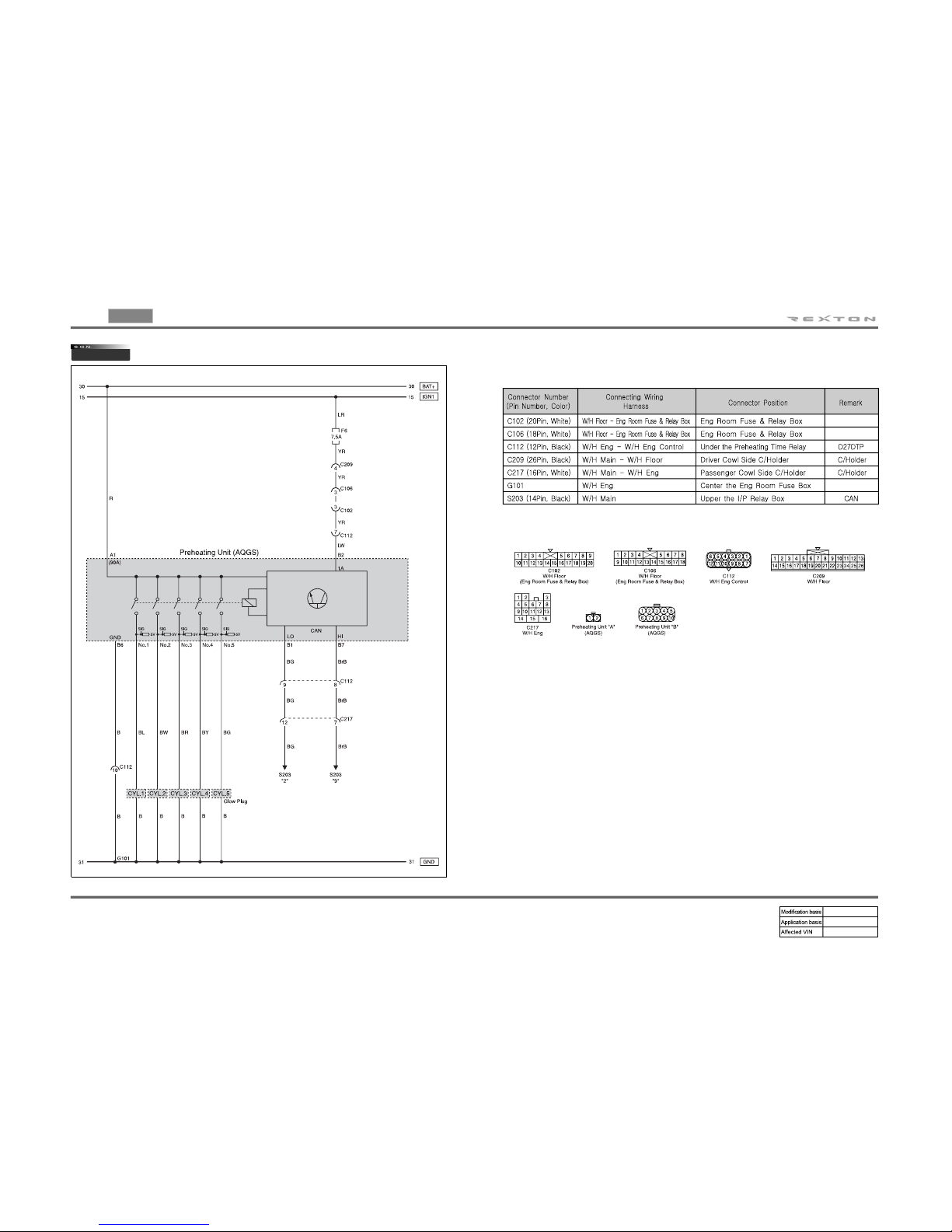
2820-01
PREHEATING CIRCUIT I - AQGS(D27DTP)
1) CONNECTOR INFORMATION
2) CONNECTOR IDENTIFICATION SYMBOL & PIN NUMBER POSITION
Page 61

0-5
CIRCUIT
REXTON 2007.09
2820-01
2820
PREHEATING CIRCUIT II (D27DT)
(1) CONNECTOR INFORMATION
(2) CONNECTOR IDENTIFICATION SYMBOL & PIN NUMBER POSITION
(3) CIRCUIT DESCRIPTION
Glow plug is installed on the cylinder head (combustion chamber) in the DSL preheating control
unit system. Cold starting performance has improved and exhaust gas during cold starting has
reduced. ECU receives coolant temperature and engine speed to control; after monitoring the
engine preheating/post heating and glow plug diagnosis function, the fault contents will be
delivered to ECU.
- Engine preheating/post heating functions
- Preheating relay activation by ECU controls
· Senses engine temperature and controls the preheating/post heating
time
· Preheating warning light
- K-LINE for information exchanges between preheating unit and ECU
· Transmits preheating unit self-diagnosis results to ECU
· Transmits glow plug diagnosis results and operating status to ECU
Page 62

0-6
REXTON 2007.09
1491-01
CIRCUIT
1491-01
ECU (ENGINE CONTROL UNIT - D27DTP)
ENG MAIN RELAY, PEDAL MODULE, HFM SENSOR, VALVE,
ENG MOUNT
1)
(1) CONNECTOR INFORMATION
(2) CONNECTOR IDENTIFICATION SYMBOL & PIN NUMBER POSITION
Page 63

0-7
CIRCUIT
REXTON 2007.09
1491-01
2) FUEL FILTER WARNING LAMP, IMMOBILIZER, SENSOR
(FUEL PRESSURE, CAMSHAFT, BOOSTER PRESSURE,
CRANKSHAFT, COOLANT/FUEL TEMP.) A/CRUISE SW
(2) CONNECTOR IDENTIFICATION SYMBOL & PIN NUMBER POSITION
(1) CONNECTOR INFORMATION
Page 64

0-8
REXTON 2007.09
1491-01
CIRCUIT
3)
(1) CONNECTOR INFORMATION
(2) CONNECTOR IDENTIFICATION SYMBOL & PIN NUMBER POSITION
INJECTOR, STOP LAMP SW, SENSOR(A/CON, E-GAS),
CLUTCH SW
Page 65

0-9
CIRCUIT
REXTON 2007.09
1491-01
1491-01
ECU (ENGINE CONTROL UNIT - D27DT)
1)
(1) CONNECTOR INFORMATION
(2) CONNECTOR IDENTIFICATION SYMBOL & PIN NUMBER POSITION
ENG MAIN RELAY, PEDAL MODULE, HFM SENSOR, VALVE,
CRUISE CONTROL SW
Page 66

0-10
REXTON 2007.09
1491-01
CIRCUIT
2) FUEL FILTER WARNING LAMP, IMMOBILIZER, SENSOR
(FUEL PRESSURE, CAMSHAFT,BOOSTER PRESSURE,
RANKSHAFT, KNOCK, COOLANT/FUEL TEMP.)
(2) CONNECTOR IDENTIFICATION SYMBOL & PIN NUMBER POSITION
(1) CONNECTOR INFORMATION
Page 67

0-11
CIRCUIT
REXTON 2007.09
1491-01
3) INJECTOR, CAN LINE
(2) CONNECTOR IDENTIFICATION SYMBOL & PIN NUMBER POSITION
(1) CONNECTOR INFORMATION
Page 68

0-12
REXTON 2007.09
1491-01
CIRCUIT
1491-01
ECU (ENGINE CONTROL UNIT - GSL G32D)
1) IGN COIL, INJECTOR, PEDAL MODULE, THROTTLE SENSOR
(1) CONNECTOR INFORMATION
(2) CONNECTOR IDENTIFICATION SYMBOL & PIN NUMBER POSITION
Page 69

0-13
CIRCUIT
REXTON 2007.09
1491-01
2) O2 SENSOR, CPS, KNOCK SENSOR, HFM SENSOR,
CANISTER PURGE VALVE
(1) CONNECTOR INFORMATION
(2) CONNECTOR IDENTIFICATION SYMBOL & PIN NUMBER POSITION
Page 70

0-14
REXTON 2007.09
1491-01
CIRCUIT
3) S/AIR PUMP, STOP LAMP, CRUISE CONTROL SW, FUEL
PUMP, IMMOBILIZER
(1) CONNECTOR INFORMATION
(2) CONNECTOR IDENTIFICATION SYMBOL & PIN NUMBER POSITION
Page 71

0-15
CIRCUIT
REXTON 2007.09
8210-01
8210-01
DIAGNOSIS CIRCUIT
2) CONNECTOR IDENTIFICATION SYMBOL & PIN NUMBER POSITION
1) CONNECTOR INFORMATION
Page 72

0-16
REXTON 2007.09
3110-01
CIRCUIT
3110-01
TCU (5SPEED - A/T)
1) START MOTOR, TGS LEVER, CAN LINE
(1) CONNECTOR INFORMATION
(2) CONNECTOR IDENTIFICATION SYMBOL & PIN NUMBER POSITION
Page 73

0-17
CIRCUIT
REXTON 2007.09
3110-01
2) SOLENOID, OIL TEMP SENSOR, SPEED SENSOR (N2, N3)
(1) CONNECTOR INFORMATION
(2) CONNECTOR IDENTIFICATION SYMBOL & PIN NUMBER POSITION
Page 74
0-18
REXTON 2007.09
3110-01
CIRCUIT
(3) CIRCUIT DESCRIPTION
A. FUNCTION
TCU controls the gear groups according to the driving conditions. It receives the driving data
from many sensors and switches as input signals. It is also connected with ECU,
HECU,instrument panel and selector lever control unit.
▶Shifting Method
Basic shift operation includes up-shift and down-shift for all gear groups. The shift control
unit determines driving resistance, accelerator pedal position, vehicle speed and some
parameters (road surface condition, up hill and down hill gradients, trailer driving
conditions, catalytic converter conditions, driving habits and automatic transmission oil
temperature) to select a shift gear.
▶Down Shift
When engine speed increases excessively, the down shift does not occur. To get an
engine brake effect during downhill driving, the current gear is maintained in speed control
mode.
▶Engine RPM Adjustment
During shifting, the engine torque is reduced to optimize the shift operation by delaying the
ignition time.
▶Lock-Up Clutch Control
The lockup clutch in torque converter is activated in 3rd, 4th and 5th gear and operates in
sequence via PWM solenoid valve.
▶Others
The transmission is automatically controlled to compensate durability and wear.
The shift control values such as shifting point, shifting time, pressure during shifting, and
lockup clutch control are permanently saved and the diagnosis is partially available.
B. MODE SWITCH
▶Function
The mode switch is installed beside the selector lever and it has two modes of “S”
mode (Standard Mode) and “W” mode (Winter Mode).
“S” mode is used in normal driving (starts off with 1st gear). TCU (Transmission
Control Unit) provides pleasant driving by changing the shifting pattern according to
the driving habits (downhill gripping: approx. 11 ~ 13.5 %)
When “W” mode is selected, the Winter mode indicator in meter cluster comes
on, and the vehicle starts off with 2nd gear to achieve smooth starting on the icy o
r
slippery road.
-
-
In winter mode, the up shift becomes faster and the down shift becomes slower fo
r
improving fuel consumption. The “W” mode is automatically changed to “S” mode in
full throttle or kick-down operation. The vehicle can starts off with 2nd reverse gear (gea
r
ratio: 1.92 ~ 1.93) when the “W” mode is selected. It is very useful on icy and
slippery road. However, in this case, the “W” switch should be selected before
placing the selector lever to “R” position.
Even though “W” mode is selected, the vehicle starts off with 1st gear in following:
When the system recognizes the mode switch operation, the selector lever control unit
sends the control signal TCU via CAN communication.
When the selector lever is in “1” position.
When fully depressing the accelerator pedal or when starting off with kick-down
condition.
-
-
Page 75

0-19
CIRCUIT
REXTON 2007.09
3110-01
C. REVERSE/PARKING (R/P) LOCK SYSTEM
Reverse (R) lock system is a safety system that prevents the selector lever from shifting to “P”
or “R” position by activating the solenoid valve when the selector lever unit determines
that the vehicle speed exceeds 10 km/h by checking the speed signal from wheel speed senso
r
via CAN communication. Parking (P) lock system uses the signals from brake switch other than
conventional cable system to shift to other positions. The wiring harness for detecting brake
switch operation is connected to selector lever control unit.
D. STARTER LOCK-OUT CONTACT SWITC
The starter lock-out contact is installed beside oil temperature sensor and is actuated by a cam
rail, which is located on the latching plate. In the selector lever positions “P” and “N”, the
permanent magnet is moved away from the reed contact. This opens the reed contact and the
transmission control module receives an electrical signal. The transmission control module
activates the starter lock-out relay module. This closes the electrical circuit to the starter in
selector lever positions “P” and “N” via the starter lock-out relay module. In other words,
when the selector lever is in driving positions, the contact is closed and the starter cannot be
operated.
E. OIL TEMPERATURE SENSOR
The oil temperature sensor is installed in hydraulic control unit and is connected in series with
the starter lock-out contact. This means that the temperature signal is transferred to TCU when
the starter lock-out contact is closed. The oil temperature has a considerable effect on the
shifting time and therefore the shift quality. By measuring the oil temperature, shift operations
can be optimized in all temperature ranges.
Gear N2 N3
1 ● -
2 ●●
3 ●●
4 ●●
5 ● -
R (S mode) ● -
R (W mode) ●●
The speed sensors are fixed to the shell of the
hydraulic control unit via the contact tabs. A lea
f
spring, which rests against the valve body,
presses the speed sensors against the
transmission housing. This ensures a precise
distance between speed sensors and impulse
rings. speed sensor (n3) detects the speed o
f
the front sun gear and speed sensor (n2)
detects the speed of the front planetary carrier.
If the speed sensor is defective, the
transmission is operated in emergency driving
mode. Below table shows the detection of speed
sensor.
F. SPEED SENSOR
G. LOCKUP SOLENOID VALVE
This valve activates and releases the lockup
clutch by adjusting the current to solenoid valve
according to engine throttle opening value and
output shaft speed. The lockup clutch operates
in 3rd, 4th and 5th gear with steps to reduce
shift shocks.
Working Current 1.5 ~ 2.0 A
Operating distance 0.2 mm
Resistance 2.5 ± 0.2 Ω
(25°C)
Operating range 3, 4, 5 shift
H. MODULATING PRESSURE (MP) AND SHIFT
PRESSURE (SP) CONTROL SOLENOID
VALVE
These valves control the modulating pressure
and the shift pressure by applying appropriate
electric current to solenoid valves according to
driving condition of engine and transmission.
When the electric current from TCU is high/low,
the regulated pressure decreases/increases.
I.
The solenoid valve remains energized and
therefore open until the shift process is
completed according to the engine and
transmission conditions. If a solenoid valve is
energized, it opens and transmits shift valve
pressure to the corresponding command valve.
CHARACTERISTICS OF UP/DOWNSHIFT
OLENOID VALVE
Working Curren 0 ~ 1.0 A
Operating distance 0.6 mm
Resistance 5 ± 0.2 Ω (25°C)
Working Curren 1.5 ~ 2.0 A
Operating distance 0.2 mm
Resistance 3.8 ± 0.2 Ω
(25°C)
Page 76

0-20
REXTON 2007.09
3410-01
CIRCUIT
3410-01
TCCU
1) CONNECTOR INFORMATION
2) CONNECTOR IDENTIFICATION SYMBOL & PIN NUMBER POSITION
Page 77

0-21
CIRCUIT
REXTON 2007.09
3410-01
3410-01
TOD
1) CONNECTOR INFORMATION
2) CONNECTOR IDENTIFICATION SYMBOL & PIN NUMBER POSITION
Page 78

0-22
REXTON 2007.09
4480-01
CIRCUIT
4480-01
EAS
1) CONNECTOR INFORMATION
2) CONNECTOR IDENTIFICATION SYMBOL & PIN NUMBER POSITION
Page 79

0-23
CIRCUIT
REXTON 2007.09
4920-01
4920-01
EPB
1) CONNECTOR INFORMATION
2) CONNECTOR IDENTIFICATION SYMBOL & PIN NUMBER POSITION
Page 80

0-24
REXTON 2007.09
4892-01
CIRCUIT
4892-01
ABS/ESP
W/SPEED SENSOR, STOP LAMP SW, DIAGNOSIS, HDC, TPMS1)
(1) CONNECTOR INFORMATION
(2) CONNECTOR IDENTIFICATION SYMBOL & PIN NUMBER POSITION
Page 81

0-25
CIRCUIT
REXTON 2007.09
4892-01
PRESSURE SENSOR, S.W.A SENSOR, SENSOR CLUSTER,
ESP OFF SW
2)
(2) CONNECTOR IDENTIFICATION SYMBOL & PIN NUMBER POSITION
(1) CONNECTOR INFORMATION
Page 82

0-26
REXTON 2007.09
4892-01
CIRCUIT
Specifications
▶
C. HBA (HYDRAULIC BRAKE ASSIST SYSTEM)
HBA (Hydraulic Brake Assist) system helps in an emergency braking situation when the
driver applies the brake fast, but not with sufficient pressure, which leads to dangerously long
braking distance. ECU recognizes the attempt at full braking and transmits the signal calling
for full brake pressure from the hydraulic booster. An inexperienced, elderly or physically
weak driver may suffer from the accident by not fully pressing the brake pedal when hard
braking is required under emergency. The HBA System increases the braking force unde
r
urgent situations to enhance the inputted braking force from the driver.
D. SWAS : STEERING WHEEL ANGLE SENSOR
The steering wheel angle sensor is located between clock spring and multifunction switch.
This sensor is used for recognition of driver’s intends. If the sensor is replaced with
new one, it can detect the neutral position after the vehicle is moving over 20 km/h for more
than 5 seconds.
E. HDC (Hill Descent Control) SYSTEM
When the slope level exceeds 10%, the HDC operates until the vehicle reaches the speed
condition given in step (4).
When the slope level is between 10% and 20% during the HDC operation
▶
When depressing the accelerator pedal or brake pedal, HDC system is changed to
stand-by mode. When depressing the accelerator pedal again, HDC starts its operation
again. Therefore, drivers can control the vehicle speed to a desired level by operating
the accelerator pedal.
When the slope level exceeds 20% during the HDC operation
▶
When depressing the accelerator pedal, HDC system is changed to stand-by mode.
When depressing the brake pedal, HDC continues its operation and the braking power is
increased. In this case, HECU sounds an abnormal noise and brake pedal may be very
rigid, but this is a normal condition due to HDC operation.
(3) CIRCUIT DESCRIPTION
A. ABS COMPONENTS
Newly introduced ABS has a different shape of integrated hydraulic modulator and HECU
(Hydraulic and Electronic Control Unit) compared to existing ABS. And, the wheel speed
sensor uses different method to detect wheel speed. The basic function of the ABS that
maintains the vehicle stability by controlling the steerability of the vehicle when braking has
not been changed.
B. ACTIVE WHEEL SPEED SENSOR
The speed sensor used in traditional ABS is made of permanent magnet and transmits the
output voltage that changes as the wheel rotor rotates to the HECU system. New wheel
speed sensor detects the wheel speed through the current value that depends on the
resistance that changes according to the magnetic field by using four resisters and supplying
the 12 V power supply to the sensor.
Page 83

0-27
CIRCUIT
REXTON 2007.09
4892-01
F. INPUT/OUTPUT SIGNALS FOR HDC OPERATION G. OPERATION OF HDC INDICATOR CONTROLLER
This table describes the coming-on and blinking mode of HDC indicator according to the HDC
switch operation (ON/OFF). The HDC indicator on the instrument panel has two modes;
green (function lamp) and red (warning lamp). The HDC switch is a push & self return type
switch ? when you press it once, it starts to operate and when you press it again, it stops the
operation.
H. ESP (ELECTRONIC STABILITY PROGRAM)
ESP (Electronic Stability Program) recognizes critical driving conditions, such as panic
reactions in dangerous situations, and stabilizes the vehicle by wheel-individual braking and
engine control intervention with no need for actuating the brake. This system is developed to
help the driver avoid the danger of losing the control of the vehicle stability due to understeering or over-steering during cornering.
Page 84

0-28
REXTON 2007.09
4892-01
CIRCUIT
I. SENSOR CLUSTER (YAW RATE SENSOR + LATERAL ACCELERATION SENSOR +
LONGITUDINAL ACCELERATION SENSOR)
J. PRESSURE SENSOR
Specificatons
▶
K. ESP WARNING LAMP BLINKING IN CONTROL
ESP warning lamp blinks when ESP control is activated. If the activation reaches a certain
limitation, a beep sounds to warn the driver. The ESP warning lamp goes off when ESP
function is deactivated. Even when the ESP is operated for a very short period of time, the
ESP warning lamp blinks minimum of 4 times every 175 milliseconds and the buzzer sounds
for at least 1.4 seconds with 100 ms interval.
L. ESP SYSTEM CANCELLATION USING THE ESP OFF SWITCH
When the ESP switch at the center switch panel is pushed (for over approximately 150 ms),
the ESP system will be cancelled and the vehicle will be driven regardless of the output
values from the corresponding sensors. Then, the ESP warning lamp on the instrument panel
comes on.
M. RESUMING THE ESP SYSTEM BY USING THE ESP OFF SWITCH
The ESP system will be resumed and the ESP warning lamp at the instrument panel goes of
f
when the ESP switch at the center switch panel is pushed (for over approximately 150 ms)
while the ESP system is not operating.
Page 85

0-29
CIRCUIT
REXTON 2007.09
4620-12
4620-12
S.S.P.S (SPEED SENSITIVE POWER STEERING
2) CONNECTOR IDENTIFICATION SYMBOL & PIN NUMBER POSITION
1) CONNECTOR INFORMATION
Page 86

0-30
REXTON 2007.09
4620-12
CIRCUIT
3) CIRCUIT DESCRIPTION
(1) SSPS (SPEED SENSITIVE POWER STEERING)
In the conventional constant power assist steering system, the steerability gets lighter as
vehicle speed rises, and this may cause a dangerous situation. Where as having heavy
steerability in high speed driving makes it difficult to manipulate the steering wheel when
vehicle is in stop. This steering system solves this problem as the steerability is changed
according to the vehicle speed, which is called Speed Sensitive Power Steering (SSPS).
SSPS, by providing appropriate steerability to a driver according to the changes of vehicle
speed, gives steering stability. The power steering control unit adjusts the hydraulic pressure
to reaction plunger by controlling the pressure solenoid valve located in the gear box to
optimize the steerability. In other words, the steering wheel gets lighter by adjusting
steerability in stop or low speed and provides steering stability by adjusting steering wheel to
become heavier in high speed.
(2) INPUT/OUTPUT OF SSPS CONTROL UNIT
(3) SSPS CONFIGURATION
A. PCV (Pressure Control Valve)
This valve controls the hydraulic pressure supplied to reaction device by moving the spool
valve according to the changes of solenoid valve.
B. Reaction device
This device increases the steerability effect by binding the input shaft with supplied hydraulic
pressure from PCV.
C. Solenoid valve
The SSPS control unit controls the amount of electric current to the solenoid valve according
to the vehicle speed. In other words, the solenoid valve controls the hydraulic pressure
applied to reaction plunger by changing the valve spool position that is linked with solenoid
valve according to the amount of electric current. The changes of hydraulic pressure applied
to input shaft according to the pressure changes applied to the reaction plunger provide
proper steerability based on the amount of electric current.
Specifications
▶
Electric Current Check
▶
Disconnect the solenoid valve connector (waterproof connector) and install the
ammeter between the solenoid valve connector and the wiring harness.
·
Do not ground the solenoid terminal.-
When the vehicle speed is at 0 km/h, check whether the electric current for solenoid
is in specified range and check that the current is reduced as the vehicle speed
increases.
-
D. SSPS Control Unit
To provide proper steerability to a driver, the SSPS control unit controls the solenoid
valve by receiving the vehicle speed and the throttle position data via CAN
communication.
The SSPS control unit controls the working current for the solenoid valve with PWM type
duty ratio of 333 Hz frequency and sets the target current to 1A during 1 second after the
ignition is “ON”.
When a trouble occurs in the system, the SSPS control unit generates a trouble code
using fail safe function.
-
-
-
Current 0.9 ~ 1.1 A (vehicle speed at 0 km/h)
Page 87

0-31
CIRCUIT
REXTON 2007.09
8810-01
8810-01
AIR-BAG (CURTAIN AIR-BAG)
2) CONNECTOR IDENTIFICATION SYMBOL & PIN NUMBER POSITION
1) CONNECTOR INFORMATION
Page 88

0-32
REXTON 2007.09
8010-01
CIRCUIT
8010-01
CLUSTER
1) GAUGE (SPEED, RPM, FUEL, TEMP), WARNING LAMP (FUEL,
FUEL FILTER, ABS/ESP, BRAKE, HDC, 4WD)
(2) CONNECTOR IDENTIFICATION SYMBOL & PIN NUMBER POSITION
(1) CONNECTOR INFORMATION
Page 89

0-33
CIRCUIT
REXTON 2007.09
8010-01
2) WARNING LAMP (EAS, EPB, AUTO PARK’G, GLOBAL), EAS
Y
LOAD’G, TPMS
(1) CONNECTOR INFORMATION
(2) CONNECTOR IDENTIFICATION SYMBOL & PIN NUMBER POSITION
Page 90

0-34
REXTON 2007.09
8010-01
CIRCUIT
3) WARNING LAMP (BATT CHARGE, OIL, SSPS, DOOR, ENG
CHECK, AIR BAG, SEAT BELT), TURN SIGNAL, FOG LAMP,
HAZARD
(1) CONNECTOR INFORMATION
(2) CONNECTOR IDENTIFICATION SYMBOL & PIN NUMBER POSITION
Page 91

0-35
CIRCUIT
REXTON 2007.09
8010-01
(3) CIRCUIT DESCRIPTION
A. INSTRUMENT CLUSTER
The instrument cluster uses the CAN communication.
The HDC warning lights (green & red) are added since the HDC function has been introduced
into ESP system.
▶Location and Configuration
B. DESCRIPTIONS OF INDICATOR DISPLAY
▶Deluxe Version
Green Turn signal, 4WD HIGH, WINTER, Parking Brake, HDC, Front fog light
Blue High beam
Red Seat belt, Battery charge, 4WD CHECK, Oil pressure, Door ajar, EBD,
Brake, Airbag, Water separator, HDC, Coolant temperature
Amber Engine CHECK, ABS, Global warning, TPMS, Fuel, Pre-glow, ESP,
4WD LOW, SSPS, Immobilizer
Page 92

0-36
REXTON 2007.09
8010-01
CIRCUIT
▶Standard Version C. WARNING LIGHTS AND INDICATORS
▶Engine Tachometer
The tachometer indicates engine speed in revolutions per minute. Multiply 1,000 to the
current number, then it will be the current number of engine revolutions.
Under the normal engine operating temperature, the proper idling speed is 750 ±
50 rpm for D27DT engine. The red zone (danger rpm range) starts from 4,500 rpm.
Connect the tachometer for tune-up test and start the engine.
Eliminate the hysteresis by tapping the tachometer.
Compare the values on the tester and tachometer and replace the tachometer if the
tolerance is excessive.
1)
2)
3)
▶Speedometer Gauge
The speedometer indicates the vehicle speed by calculating the signals from the rea
r
wheel speed sensors through ABS or ESP unit (speed signal cycle: 21 ms). If the
speedometer gauge vibrates, stops at a certain range or makes an abnormal noise, there
could be defectives in speedometer. However, these symptoms also could be occured
when the tire has uneven wear, different tire inflation pressures or different tire
specifications. Perform the speedometer test regarding the tolerance as described.
However, it is not similar simple work in field due to lack of measuring conditions such as
test equipment and preciseness.
Check the allowable tolerance of the speedometer and operations of the trip odometer
by using atester.
Check if the speedometer gauge is shaking and the abnormal noise sounds.
Eliminate the hysteresis by tapping the speedometer.
1)
2)
3)
Page 93

0-37
CIRCUIT
REXTON 2007.09
8010-01
▶Fuel Level Gauge
The fuel level gauge displays the resistance value of the float on the fuel sender in the
fuel tank through a pointer. Note that this vehicle doesn't have a service hole fo
r
checking the fuel sender connector in the fuel tank. The fuel sender and its connecto
r
can be checked and replaced only when the fuel tank is removed. The power supply and
resistance value should be measured at the connector in front of the fuel sender (refer to
wiring diagram). When the power supply and output resistance are normal, the float
operation by fuel level may be defective; if so, replace the fuel sender.
▶Tolerance and resistance value by indicating angle
This table shows the tolerance and resistance value changes by fuel level in normal conditions.
Therefore, the differences that can be occurred by the road conditions and fuel fluctuations are
ignored.
▶Coolant Temperature Gauge
Using a needle, it displays the coolant temperature obtained from the engine coolant
temperature sensor. The PTC resistance value of the coolant temperature sensor is
transmitted to the engine ECU and then to the cluster as CAN signal. The angle o
f
guage that can be varied by coolant temperature is as shown below.
▶Measurement of coolant temperature sensor resistance
Measure the resistance between the terminal and the ground with an ohmmeter and
replace if the resistance is out of specified range.
Resistance value by coolant temperature: 20°C - 2449Ω ± 5 %
50°C - 826Ω ± 5 %
80°C - 321Ω ± 5 %
100°C - 12Ω ± 5 %
When the resistance value by coolant temperature is within the specified range, check
thermostat, water pump, radiator related coolant circuit for normal operation.
A
lso,
check the wiring harnesses and connectors for proper connection (D27DT engine
ECU: NO.101, 102 / D27DTP (power up) engine ECU: A56, A57).
The time when the engine coolant temperature reaches the normal temperature
(gauge indicating angle: 0°) depends on the ambient temperature and the
vehicle's load. Therefore, the coolant temperature gauge should be used only fo
r
reading its movement.
-
-
▶PRESS “RESET BUTTON” TO GO THE EACH MODE
Mode changes
Page 94

0-38
REXTON 2007.09
7410-13
CIRCUIT
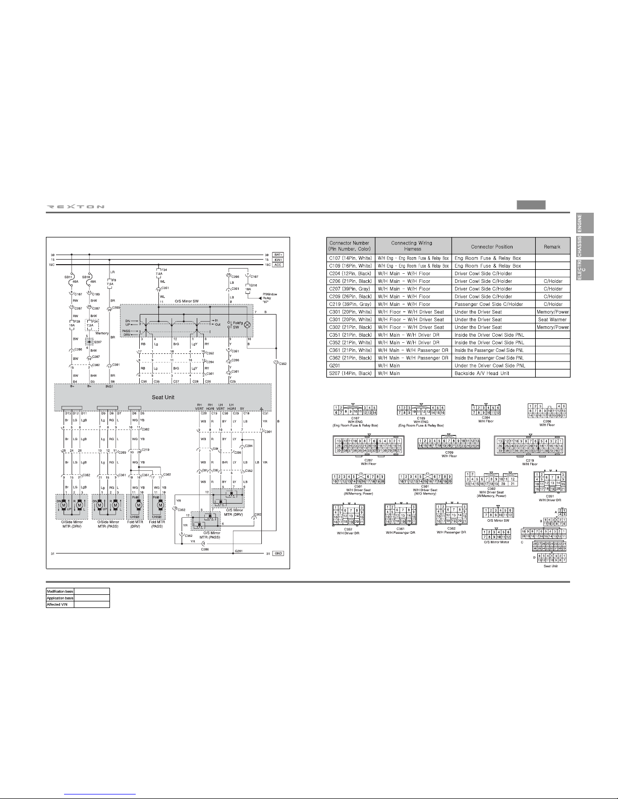
7410-13
POWER SEAT - DRIVER (W/ MEMORY)
1) DRIVER POWER SEAT & SEAT MEMORY
(1) CONNECTOR INFORMATION
(2) CONNECTOR IDENTIFICATION SYMBOL & PIN NUMBER POSITION
Page 95
0-39
CIRCUIT
REXTON 2007.09
7410-13
2) ELECTRIC OUTSIDE MIRROR & FOLDING
(1) CONNECTOR INFORMATION
(2) CONNECTOR IDENTIFICATION SYMBOL & PIN NUMBER POSITION
Page 96

0-40
REXTON 2007.09
7410-13
CIRCUIT
(3) CIRCUIT DESCRIPTION
A. FUNCTION AND DESCRIPTION
Basic function: Adjustment and memorization of driver’s seat position,
Folding/Unfolding the outside rearview mirrors.
Additional function: Easy access function, Aiming down (3.5°) when reversing Deleted
component: Outside rearview mirror folding unit (model with SPWM) However, for the vehicle
without SPWM, the outside rearview mirror folding unit is installed in front of STICS.
B. MAJOR FUNCTIONS OF SPWM UNIT
Driver’s Power Seat
▶
The control the SPWM unit, the ignition ON/OFF signal is transmitted to SPWM unit from
STICS. However, the parking brake signal and transmitted to SRWM unit from the instrument
cluster.
- Power Seat Position Control
- Outside Rearview Mirror Control
- Driver's Seat and Outside Rearview Mirror Position Memory
- Easy Access
- Outside Rearview Mirror Auto Down
C. SPECIFICATIONS
▶Actuator
▶Outside Rearview Mirror
- Manual Mode (Normal): 12V
- Position Sensor and Folding Switch
Page 97

0-41
CIRCUIT
REXTON 2007.09
7410-13
D. EASY ACCESS FUNCTION▶Motor
▶Motor Output (normal mode: ground)
▶Buzzer
- Output time: 2Hz, DUTY 20% (ON: 0.1 sec., OFF: 0.4 sec.)
- Buzzer output conditions
When the memory operation is permitted (memory switch ON): once
After completing the memory recall (position switch ON): twice
When starting to recall the memory (position switch ON): once
When pressing the position switch button twice consecutively: three times
When detecting a sensor error while recalling (position switch ON): three times
No buzzer output for the easy access memory/recall operations
No buzzer output for the outside mirror position recall by the auto down operation
when reversing
·
·
·
·
·
·
·
This system is designed to provide a sufficient space for the driver to access and exit by
moving the seat rearwards.
Easy access permissible conditions:
Page 98

0-42
REXTON 2007.09
7410-04
CIRCUIT
7410-04
POWER SEAT - PASSENGER
2) CONNECTOR IDENTIFICATION SYMBOL & PIN NUMBER POSITION
1) CONNECTOR INFORMATION
Page 99

0-43
CIRCUIT
REXTON 2007.09
8510-52
8510-52
nullELECTRIC OUTSIDE MIRROR & FOLDING (W/O
MEMORY)
1) CONNECTOR INFORMATION
2) CONNECTOR IDENTIFICATION SYMBOL & PIN NUMBER POSITION
Page 100

0-44
REXTON 2007.09
8510-48
CIRCUIT
8510-48
FRT SEAT WARMER (W/ MEMORY)
1) CONNECTOR INFORMATION
2) CONNECTOR IDENTIFICATION SYMBOL & PIN NUMBER POSITION
 Loading...