

TSDS1A01 02.18.03
Single Shot (Pulse Former)
TSDS Digi-Timer
Timing Module
n
ecificatio
p
S
te
+/-0.5% Repeat Accuracy
No First Shot Effect
Stable Over Voltage & Temperature
Fixed or Adjustable Delays From 0.1 s ... 1000 m
Totally Solid State & Encapsulated
le
so
b
O
Redesigned product is available
see new specifications at:
www.ssac.com/standard/standard.htm
Description
The TSDS utilizes a stable oscillator for its time
base and a C/MOS digital predetermined counting
circuit to provide excellent repeat accuracy.
Suitable for many applications including
dispensing, welding, exposure timing--those
applications requiring single shot timing.
Operation
Input voltage must be applied before and during
timing. Upon momentary or maintained closure
of the initiate switch, the output is energized for a
measured interval of time. At the end of the delay ,
the output de-energizes. Opening or reclosing
the initiate switch during timing has no affect on
the time delay. The output will not energize if the
initiate switch is closed when input voltage is
applied.
Reset: Reset occurs when the time delay is
complete and the initiate switch is opened. Loss
of input voltage resets the time delay and output.
Approvals:
Ordering T able
TSDS X X X X
Series
Example P/N:
Input Adjustment Time Delay*
–1 - 12 V DC –1 -–0 - 0.1 … 10 s
2 - 24 V AC –2 -–1 - 1 … 100 s –P -
–
3 - 24 V DC –2 - 10 … 1000 s –N -
–
4 - 120 V AC –3 - 0.1 … 10 m
–
6 - 230 V AC –4 - 1 ... 100 m
–
TSDS421 Fixed – TSDS410.1S
Fixed
External
Adjust
5 - 10 … 1000 m
–
Switching Mode
(V DC Only)
Positive
Negative
* If Fixed Delay is
selected, insert delay
[
0.1 … 1000] followed
by (
S) sec. or (M) min.
Technical Data
Time Delay
Type Digital integrated circuitry
Range 0.1 s ... 1000 m in 6 adjustable ranges or fixed
Repeat Accuracy +/-0.5 %
Tolerance (Factory Calibration) +/-1%
Recycle Time ≤ 150 ms
Time Delay vs. Temperature & Voltage ≤ +/-2%
Input
Voltage 12 or 24 V DC; 24, 120, or 230 V AC
Tolerance +/-15%
DC Ripple +/-10%
Line Frequency 50 ... 60 Hz
Output
Type Solid state
Form Normally Open, closed during timing
Maximum Load Current 1 A steady state, 10 A inrush at 55° C
Voltage Drop DC ≅ 1.7 V at 1 A
DC Operation Positive or negative switching
Protection
Circuitry Encapsulated
Dielectric Breakdown ≥ 2000 V RMS terminals to mounting surface
Insulation Resistance ≥ 100 MΩ
Mechanical
Mounting Surface mount with one #10 (M5 x 0.8) screw
Package 2 x 2 x 1.21 in. (50.8 x 50.8 x 30.7 mm)
Termination 0.25 in. (6.35 mm) male quick connect terminals
Environmental
Operating/Storage Temperature -40°C ... +75°C / -40°C ... +85°C
Humidity 95% relative, non-condensing
Weight ≅ 2.4 oz (68 g)
Inches (Millimeters)
0 – 0.1 ... 10 s
1 – 1 ... 100 s
2 – 10 ... 1000 s
3 – 0.1 ... 10 m
4 – 1 ... 100 m
5 – 10 ... 1000 m
AC ≅ 2.5 V at 1 A
VTP P/N Time Delay
VTP2C
VTP2G
VTP2K
VTP2N
VTP2P
VTP4R
Fig. A P/N
P1004-16
P1004-16
P1004-16
P1004-16
P1004-16
P1004-12
Fig. B P/N
P1004-16-X
P1004-16-X
P1004-16-X
P1004-16-X
P1004-16-X
P1004-12-X
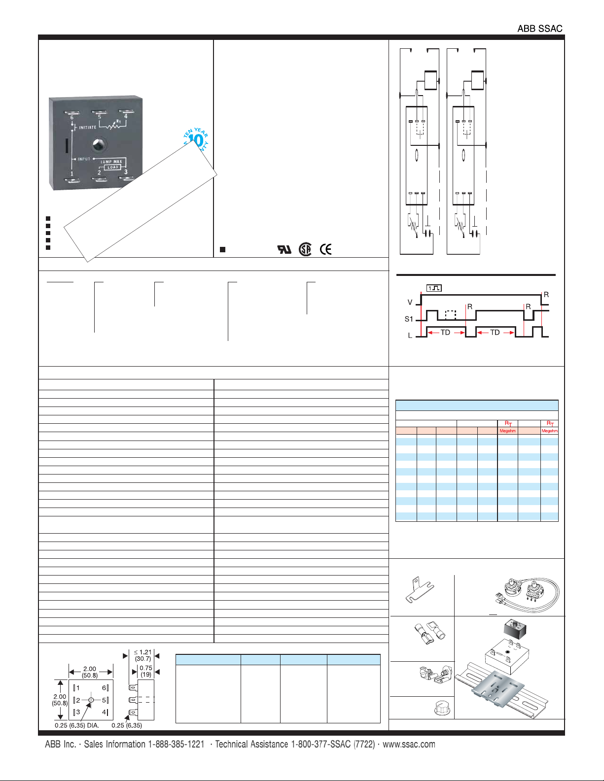
Positive Switching
2
1
3
456
R
T
R
is used when external adjustment is ordered.
T
V = Voltage L = Load TD = Time Delay
S1 = Initiate Switch R = Reset
Seconds
0
12
0.1 1 10 0.1 1 0.0 10 0.0
1 10 100 1 10 0.1 100 0.3
2 20 200 2 20 0.2 200 0.6
3 30 300 3 30 0.3 300 0.9
4 40 400 4 40 0.4 400 1.2
5 50 500 5 50 0.5 500 1.5
6 60 600 6 60 0.6 600 1.8
7 70 700 7 70 0.7 700 2.1
8 80 800 8 80 0.8 800 2.4
9 90 900 9 90 0.9 900 2.7
10 100 1000 10 100 1.0 1000 3.0
* When selecting an external RT add at least 11%
for tolerance of unit and the RT.
2
1
3
456
Negative Switching
R
T
Single Shot
R Selection Chart
T
Desired Time Delay*
Minutes
34
Minutes
5
Accessories
B
External
Mounting bracket
P/N: P1023-6
Female
quick
connect
P/N:
(AWG 14/16)
P1015-64
Quick
connect to
screw adaptor
P/N: P1015-18
Versa-knob
P/N: P0700-7
See accessory pages at the end of this section.
adjust
potentiometer
P/N: P1004-
Plug-on
adjustment
module
P/N:
VTP(X)(X)
F
o
→
DIN rail adaptor
P/N: P1023-20
XX
r
illu
s
t
r
a
t
io
n
17322005 (Steel)
DIN rail P/Ns:
C103PM (Al)
←
A
127
 Loading...