

Page 1

TVW SeriesVoltage Monitors
Provides protection for motors and other sensitive
loads. Continuously measures the voltage of
each of the three phases using a microcontroller
circuit design that senses under and overvoltage,
voltage unbalance, phase loss, and phase reversal.
Protection is provided even when regenerated
voltages are present. Includes a trip delay to
prevent nuisance tripping and a restart delay to
prevent short cycling after a momentary power
outage.
For more information see:
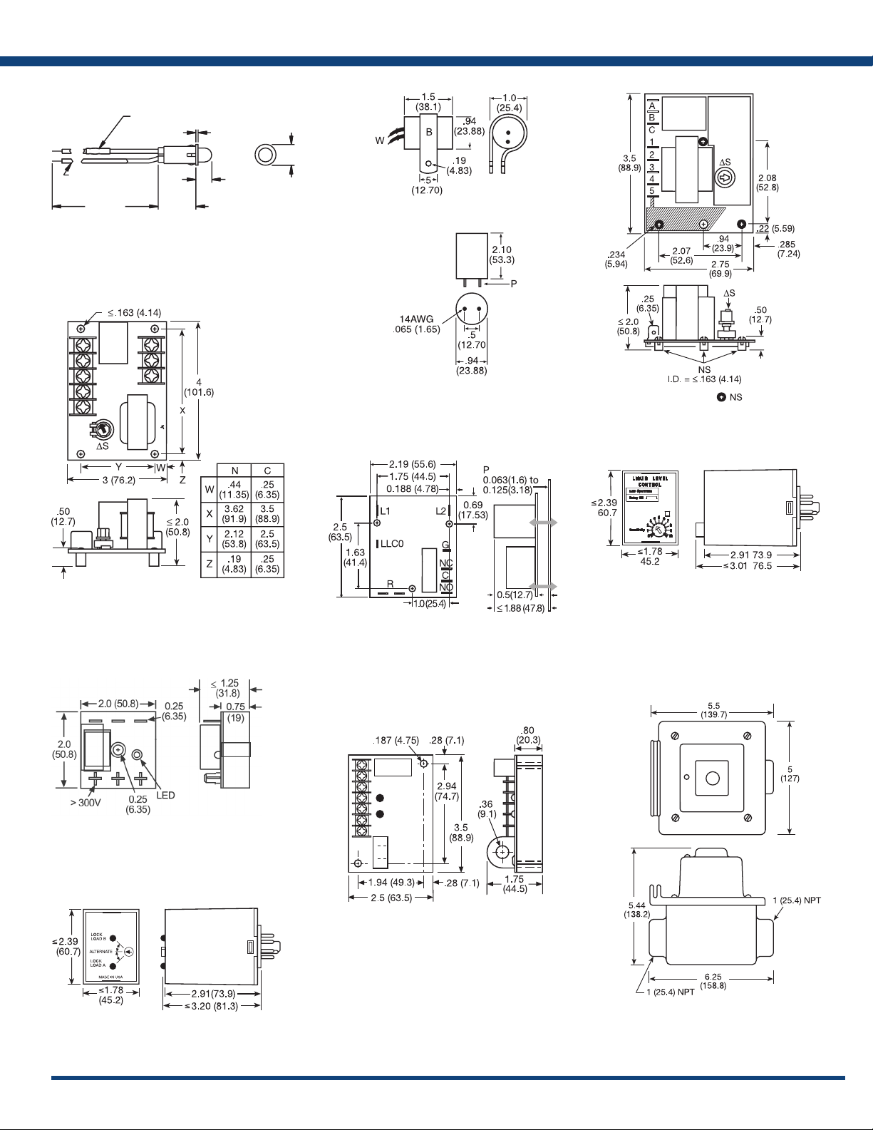
Appendix B, page 167, Figure 30 for dimensional drawing.
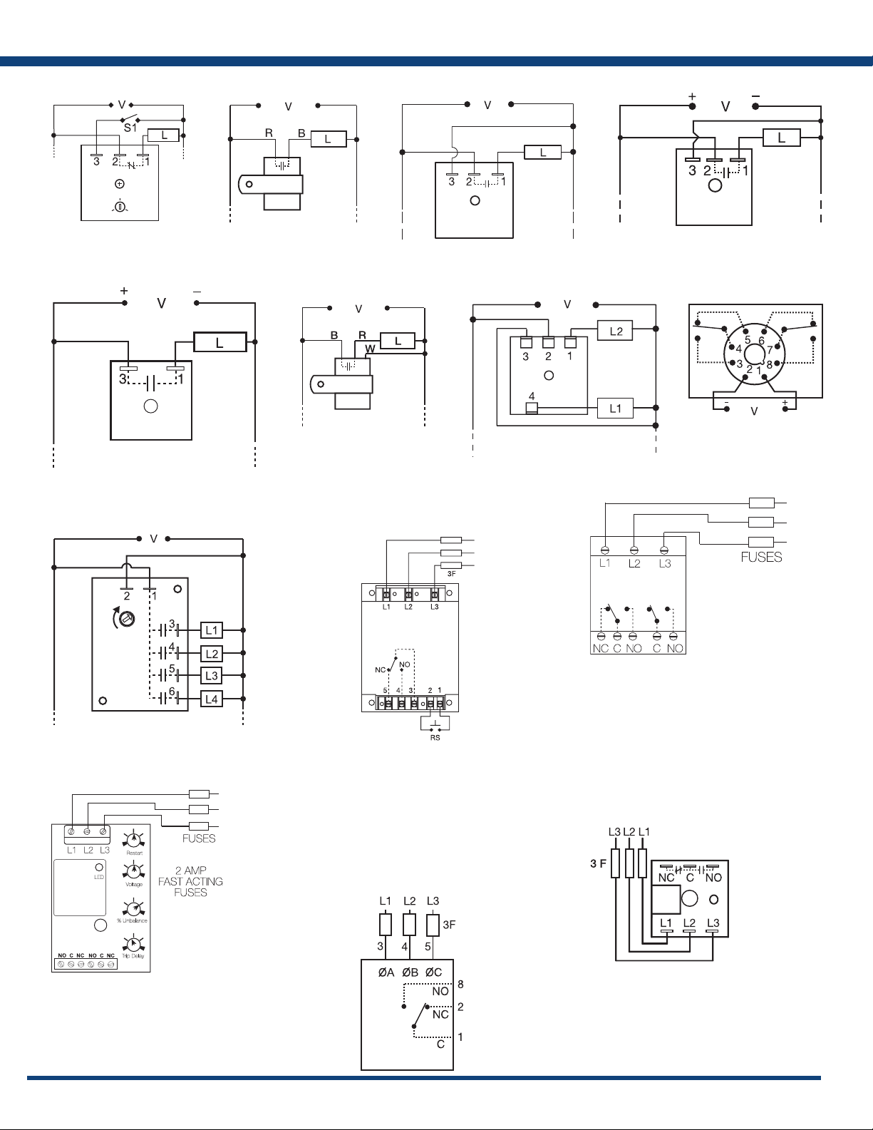
Appendix C, page 168, Figure 14 for connection diagram.
Operation
Upon application of line voltage, the restart delay begins. The output is de-energized during restart delay. Under
normal conditions, the output energizes after the restart delay. Undervoltage, overvoltage, and voltage unbalance
must be sensed for the complete trip delay period before the output de-energizes. The restart delay begins as
soon as the output de-energizes. If the restart delay is completed when a fault is corrected, the output energizes
immediately. The output will not energize if a fault is sensed as the input voltage is applied. If the voltage selector
is set between two voltage marks (i.e. between 220 and 230V), the LED will ash red rapidly. The TVW provides
fault protection at the lower of the two line voltages (i.e. 220V).
Reset: Reset is automatic upon correction of a fault.
LED Operation
The LED ashes green during the restart delay, then glows green when the output energizes. It ashes red during
the trip delay then glows red when the output de-energizes. It ashes red/green if phase reversal is sensed. If
the voltage selector knob is between settings, it rapidly ashes red.
Features:
• Protects against phase loss & reversal; over,
under & unbalanced voltages; short
cycling
• Fixed trip points & delays
• Adjustable voltages from 208 to 480VAC
in 4 ranges
• Monitor 600VAC lines by connecting VRM
accessory
• Isolated, 10A, SPDT output contacts
• Bi-color LED indicates: output status, faults,
time delays, phase reversal & setpoint
• ASME A17.1 rule 210.6
• NEMA MG1 14:30, 14:35
• IEEE C62.41-1991 Level B
Approvals:
Auxilary Products:
• 3-phase fuse block/disconnect:
P/N: FH3P
• 2 Amp fuse: P/N: P0600-11
• DIN rail: P/N: C103PM (Al)
• Female quick connect:
P / N: P 10 1 5- 1 3 ( A WG 10 /1 2 )
P/N: P1015-64 (AWG 14/16)
P/N: P1015-14 (AWG 18/22)
• Voltage reduction module:
P/N: VRM6048
Order Table:
TVW
X
Line Voltage
Wide Range
─5 - 208-240VAC
Selectable
─6 - 208, 220, 230 & 240VAC
─8 - 380, 400 & 415VAC
─9 - 430, 440, 460 & 480VAC
X
Voltage Unbalance
─Fixed - Specify 4-10%
in 1% increments
X
Trip Delay*
─Fixed - Specify from 0.2-1s
in 0.1s increments
─Fixed - Specify from
1-100s in 1s increments
*Must indicate (S) for secs. or (M)
for mins.
Specications
Line Voltage
Type .....................................
Input Voltage/Tolerance ...................208 to 480VAC in 4 ranges/-30% - 20%
AC Line Frequency ........................50 - 100 Hz
Phase Sequence ...........................ABC
Power Consumption ....................... Approx. 2W for 240V units
Approx. 3W for 480V units
Overvoltage, Undervoltage, & Voltage Unbalance
Overvoltage & Undervoltage ................Voltage detection with delay trip & automatic
reset
Undervoltage Trip Point ....................88 - 92% of the selected line voltage
Reset Voltage .............................≅ +3% of trip voltage
Overvoltage Trip Point .....................109 - 113% of the selected line voltage
Reset Voltage .............................≅ -3% of trip voltage
Trip Variation vs Temperature ..............≤ ±2%
Voltage Unbalance .......................Factory xed, from 4 - 10%
Reset On Balance ..........................≅ -0.7% unbalance
Trip Delay Range ..........................Fixed from 0.2 - 100s ±15% or ±0.1s,
whichever is greater
Restart Delay Range .......................Fixed from 0.4s - 999m ±15% or ±0.2s,
whichever is greater
3-phase delta or wye with no connection to neutral
Available Models:
TVW575S1M
TVW6510S0.4S
TVW9510S0.4S
If desired part number is not listed, please call us to
see if it is technically possible to build.
X
Restart Delay*
─Fixed - Specify from 0.4-1s
in 0.1s increments
─Fixed - Specify from 1-100s in 1s
increments
─Fixed - Specify from 1-999min in
1min increments
Phase Reversal & Phase Loss Response
Phase Loss ................................≥ 25% unbalance
Output
Type .....................................Isolated, SPDT
Rating 208 to 240VAC (55°C) ......10A resistive @ 125VAC, 5A @ 250VAC,
1/4 hp @ 125VAC
380 to 480VAC ............10A resistive @ 240VAC, 1/4 hp @ 125VAC,
1/3 hp @ 250VAC, max. voltage 277VAC
Life ......................................Mechanical - 1 x 10⁶; Electrical - 1 x 10
Protection
Surge ....................................IEEE C62.41-1991 Level B
Dielectric Breakdown 208 to 240VAC. . . . . . . ≥ 1500V RMS input to output terminals
380 to 480VAC ......≥ 2500V RMS input to output terminals
Mechanical
Mounting ................................Surface mount with one #8 (M5 x 0.8) screw
Dimensions ...............................2 x 2 x 1.25 in. (50.8 x 50.8 x 31.8 mm)
Termination ..............................0.25 in. (6.35 mm) male quick connect
terminals
Environmental
Operating / Storage Temperature ...........-40° to 55°C / -40° to 85°C
Humidity .................................95% relative, non-condensing
Weight ...................................≅ 2.8 oz (79 g)
.......≤ 200ms; automatic reset
5
115
Page 2
Appendix B - Dimensional Drawings
FIGURE 24
24 AWG (0.25 mm
UL1007
STRIPPED 0.25 (6.35)
12 ± 1
(304.8 ± 25.4)
LPM
FIGURE 27
CURRENT LIMITING
RESISTOR
2
)
0.53
(13.46)
<
_
0.22
(5.59)
0.28
(7.11)
FIGURE 25
MSM
FIGURE 28
FIGURE 26
= Nylon Standoffs
LLC1
FIGURE 29
LLC2
FIGURE 30
TVM; TVW
FIGURE 31
LLC8
FIGURE 32
FB; SCR
[ ]
LLC5
[ ]
FIGURE 33
[ ]
[ ]
ARP
PCR
inches (millimeters)
167
Page 3
Appendix C - Connection Diagrams
L1 N/L2
FIGURE 1 - FSU1000 Series
L1 N/L2
S1 = Optional low current switch
V = Voltage
L = Load
FIGURE 5 - FS300 Series
V = Voltage
L = Load
Note: Load may be in positive side.
FIGURE 2 - FS100 Series
L1 N
V = Voltage
L = Load
R = Red Wire
B = Black Wire
FIGURE 6 - FS400 Series
L1 N/L2
V = Voltage
L = Load
R = Red Wire
B = Black Wire
W= White Wire
FIGURE 3 - FS100 Series FIGURE 4 - FS200 Series
L1 N/L2
V = Voltage
V = Voltage
L = Load
FIGURE 7 - AF Series
L1 N/L2
V = Voltage
L = Load
L = Load
FIGURE 8 - FS500 Series
L1 N/L2
V = Voltage
FIGURE 11 - DLMU Series
FIGURE 9 - SC3/SC4 Series
SC4 shown;
for SC3, terminal 6 & load L4 are eliminated.
FIGURE 12 - HLMU Series
Note: Relay contacts are
L1, L2, L3 = Line Voltage Input
NO = Normally Open Contact
NC = Normally Closed Contact
C = Common, Transfer Contact
CAUTION: 2 amp max. fast acting fuses are
recommended to protect the equipment‘s
wiring. They are not required to protect the
HLMU.
isolated, 277VAC max.
FIGURE 10 - WVM Series
F = Fuses
NO = Normally Open
NC = Normally Closed
Optional Remote Reset Switch
RS =
Relay contacts are isolated.
CAUTION:
2 amp max fast acting fuses must
be installed externally in series
with each input. (3)
FIGURE 13 PLMU/PLM/PLR/PLS Series
F = Fuses
ØA = Phase A = L1
ØB = Phase B = L2
ØC = Phase C = L3
NO = Normally Open
NC = Normally Closed
2A fast acting fuses
recommended for safety (not
required)
Relay contacts are isolated.
!
L1, L2, L3 = Line Voltage Input
NO = Normally Open Contact
NC = Normally Closed Contact
C = Common, Transfer Contact
CAUTION: 2 amp max. fast acting
fuses are recommended to protect
the equipment‘s wiring. They are not
required to protect the DLMU.
! = Select alarm contact connection as N.O. or
N.C. when ordering; N.O. Shown.
FIGURE 14 TVM/TVW Series
L1 = Phase A
L2 = Phase B
L3 = Phase C
NO = Normally Open
NC = Normally Closed
C = Common, Transfer Contact
Relay contacts are isolated.
F = 2A Fast acting fuses are recommended,
but not required
168
 Loading...